It is known that high voltages operate in cable and overhead power lines of transformer substations, during the transmission of which it is especially important to take precautions. Like 380-volt power supply systems, high-voltage lines (OHVs) are connected according to circuits that provide effective protection against damage by the voltages acting in the circuit.
At the same time, in accordance with the requirements of the PUE, the neutral point of the supply transformer (neutral) is most often reliably grounded, that is, connected to a grounding device specially equipped for these purposes - the charger.
Methods for turning on neutral
The specificity of the operation of high-voltage (HV) systems is that in the event of a line break or damage, accompanied by a short circuit of a separate wire to ground, leakage currents can reach very large values.
Accordingly, the protective measures taken in such networks differ markedly from similar actions in the end-user circuits.
For 6-35 kilovolt networks, the neutral grounding modes listed below are typical:
- direct connection to a charger located directly at a substation or at a high-voltage pole (solidly grounded neutral ground);
- connection through a special arc suppression reactor or compensator;
- using a grounding system for these purposes, in which the neutral is connected through a resistor;
- without connection to the charger within the boundaries of the protected line or object (isolated neutral).
Installation of special compensation elements in the connection circuit of the neutral conductor helps to reduce the capacitive components of the fault currents.
During the operation of such a chain, these currents can be neutralized due to a smooth change in the inductance of the coil, the voltage in which has a reverse phase.
At a certain value of inductance, the current at the point of closure of the ground electrode to the ground decreases to zero. To increase the efficiency of such grounding, a resistor is connected parallel to the inductance, providing conditions for the drainage of the active component of the current used to operate the high-voltage protection relay. Other options for turning on the neutral will be discussed separately below.
Each of these schemes requires the installation of a separate charger on the receiving side, which ensures re-grounding of the neutral and creates safe operating conditions for the overhead line.
Without this device, the switching circuits used cannot effectively perform their protective functions, since if the neutral conductor accidentally breaks, the power equipment of the substations will remain unprotected.
Another option is possible, in which the grounding of the neutral in 6-35 kV networks is carried out through the inclusion of a common point in the supply network, called effective grounding and implemented through the creation of almost ideal conditions for the flow of current into the ground.
However, it is considered too expensive and is usually used only at supply substations with input voltages of 110 kilovolts and higher.
How to choose equipment?
Being a highly specialized piece of equipment, the mechanism must perform specific tasks. The ability to guarantee their implementation is the best indicator of the conformity of the device. These are:
- Device resistance values that guarantee the flow of current (active) in the damaged connection with sufficient current. It must ensure the disconnection of the faulty connection, or the operability of the relay protection for the signal.
- Compliance with electrical safety conditions for people during occupational safety at distribution points and substations. In this case, the effective values of possible touch voltage are taken into account.
- Reduction of arc overvoltages.
← Previous article Next article →
Systems with isolated neutral from earth
The mode of operation of networks with an isolated neutral is quite common in most regions of Russia. With this connection method, the neutral point of the supply generator (transformer) with the windings arranged in a “delta” pattern remains ungrounded.
The reason for the demand for the option under consideration is that with this scheme for connecting the neutral, any phase-to-ground fault cannot be considered short (due to the lack of connection through the ground).
Moreover, in such an emergency mode, the high-voltage network can operate without much damage for several hours.
Other advantages of this scheme include low currents at the point of a single-phase ground fault (FGC) due to the insignificant network capacitance relative to the ground.
The short circuit currents with this connection option are significantly less than in the case of interphase faults, which is another advantage of these networks.
In this regard, such systems do not require special fast-acting means of protection against hazards, which significantly reduces the cost of their operation.
The significant disadvantages of such a connection include:
- the possibility of the formation of overvoltages with arcing effects and relatively small currents (up to tens of amperes) at the OZZ point;
- the associated possibility of damage to cable or explosive equipment due to insulation destruction due to arc overvoltages;
- the requirement to take into account increased (linear 380 Volt) voltage, if necessary, reliably isolate linear electrical equipment;
- difficulty in identifying the exact location of damage.
Thus, before choosing this method of connecting the neutral, all the pros and cons must be taken into account, and the possible consequences of emergency modes must be calculated.
Neutral grounding modes
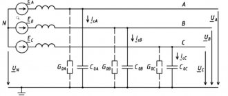
In Russia, 6-35 kV distribution networks operate in a mode with a non-solidly grounded neutral . When a single-phase ground fault (SFG) occurs, the current in such networks is short-circuited back to the source through the capacitances of the undamaged phases (due to the absence of a neutral), in contrast to networks with a grounded neutral, in which the current is “short-circuited”, returning back to the source through a grounded neutral Thus, the resistance along the current path during short circuit protection in networks with a non-solidly grounded neutral is greater than in networks with a solidly grounded neutral.
A big advantage of operating networks with a non-solidly grounded neutral is the low values of ground fault currents, but the physics of the short-circuit fault processes is such that with a metal short-circuit fault in such networks, the voltage relative to the ground in undamaged phases increases to a linear level, which is a negative factor. For this reason, the use of this type of neutral is limited (only up to a voltage of 35 kV), since at higher voltages it is not economically profitable to provide phase insulation capable of withstanding line voltage.
Approximately 79% of 6-35 kV networks in Russia have an isolated neutral, 19% are grounded through a DGR. Also recently, solutions with resistive neutral grounding have been introduced.
Since 6-35 kV networks are made with phase insulation that can withstand voltage increases up to linear, and the short-circuit currents have quite small values that do not affect consumers in any way, the idea arises not to disconnect this type of damage at all until the necessary operations have been carried out switching the consumer to a source without OZZ. After this, you can safely eliminate this type of damage . This is the ideology of the operation of networks with an isolated neutral mode (when the neutral point is not electrically connected to the ground).
But as practice shows, the consequences of SPL in networks with an isolated neutral can be as follows:
- In the case of an OZZ with this type of neutral, there is a high probability of an arc intermittent ground fault , in which the voltage may increase by 3.5 times relative to the rated voltage of the phase insulation. Thus, there is a high probability of a secondary insulation breakdown at any other point in the network and the transition of a single-phase ground fault into double and multiple faults, which are accompanied by a large number of power line outages. Also, during an arc fault to ground, there is the possibility of significant damage due to overvoltage of the insulation of electrical machines;
- High degree of danger for humans and animals located near the site of a single-phase ground fault;
- The possibility of ferroresonance processes occurring in the network, which are accompanied by damage to voltage transformers.
For these reasons, two approaches have emerged to eliminate the above-mentioned negative consequences of this type of neutral, namely:
- Neutral grounding via adjustable reactor;
- Grounding through a resistor.
The principle of grounding through a reactor is based on identifying the value of the network capacitance and subsequent adjustment of the inductance value in the neutral so as to reduce the short-circuit current at the fault site to a minimum. This solution reduces the likelihood of an arc fault to ground and ferroresonance processes, and also increases electrical safety in the area of the fault by reducing the current of the fault.
This decision has the following negative consequences:
- Additional costs for installing expensive equipment;
- The operation of the network with OZZ depends on the operation of the automatic reactor adjustment, which has low reliability associated with compensation misalignment;
- Even with ideal compensation of the short-circuit current, there are still uncompensated higher harmonic currents and an active component of the short-circuit current in the network. Thus, the presence of a reactor in the neutral, although it reduces the likelihood of breakdowns during short-circuit faults and ferroresonance processes, still the presence of residual current in the place of the short-circuit fault does not exclude these breakdowns and processes (the arc may not be extinguished) and negatively affects the electrical safety of using this type of neutral .
- There is a limitation on the development of the network, since the reactor is designed to compensate for only a certain value of the capacitive current, and as the network develops, the OPC current increases and the capabilities of the existing reactor may not be enough .
An alternative to using a reactor in the neutral is to use a resistor .
Resistors are:
- high-resistance (when the resistor resistance is equal to the capacitive reactance of the network);
- low-resistance (when the installed resistor has such a minimum possible resistance that the flowing ground fault current does not cause serious damage during the protection period).
Thus, the idea of resistive grounding of the neutral, in contrast to grounding through the reactor, is aimed at completely eliminating arc faults and ferroresonance processes.
Disadvantages of high-resistance neutral grounding:
- Additional costs for installing expensive equipment (the cost of installing a resistor is lower than the cost of installing a reactor);
- The magnitude of overvoltages is reduced to 2.5 relative to the phase voltage, but they are not completely eliminated;
- Restriction on network development , since the resistor is designed only for a certain OZZ current;
- A prerequisite for disabling the OZZ, since the resistor is not capable of operating for a long time in the OZZ mode . It is also necessary to have additional thermal protection for the resistor in case of short circuit protection.
Disadvantages of low-resistance neutral grounding:
- Additional costs for expensive equipment (the cost of installing a resistor is lower than the cost of installing a reactor);
- Possibility of increasing the amount of damage to electrical equipment during SFZ due to an increase in SFZ current;
- Restriction on network development , since the resistor is designed only for a certain OZZ current;
- The resistor is not capable of operating for a long time in OZZ mode.
Since the use of grounding through a resistor and reactor has its pros and cons, there is a solution for combined neutral grounding, that is, installing a resistor and reactor in parallel in the neutral. This solution compensates the short-circuit current to the minimum possible level and at the same time eliminates arc and ferroresonance processes during short-circuit faults.
Thus, it is clear that at the moment there is still no final decision on which neutral mode is better. It is necessary to select a specific neutral grounding mode for specific networks. Based on a feasibility study.
Re-grounding
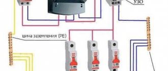
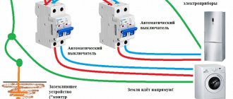
Re-grounding of the neutral conductor is protection installed at the intervals specified by the rules of the Electrical Installation Code along the entire length of the neutral. The task of re-grounding includes reducing the voltage in the neutral wire and electrical appliances that have been grounded relative to the ground. This property is useful as protection against a break in the neutral wire and in the event of a breakdown of electrical voltage on the housing of electrical devices.
To reconnect, it is necessary to conduct a continuous neutral from the shield to the neutral conductors. In high-rise buildings, various systems are used for re-grounding.
TN
The transformer neutral in electrics is grounded, and the accessible part is connected to it through neutral protective conductors. In normal mode, the electrical receiver is not energized. The TN system is:
- TN-S – the protective and neutral conductors are separated along the length of the entire line;
- TN-CS - the functions of the PE and N wires are combined in one part of the conductor brought out from the transformer.
If communications are connected in a private house, natural grounding conductors are used - metal pins in the ground. Regulatory documents do not recommend the use of natural conductors, since it is impossible to calculate the resistance that the soil provides when current flows.
TN-C
TT
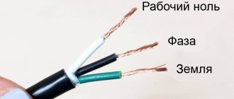
Grounding in houses built before the mid-90s, for which a four-wire method was used - 3 phases and 1 zero. The protective and working functions of the neutral are performed by a common conductor throughout the entire line. The consumers are powered from a PEN cable. It is also used for grounding.
IT
It is used to supply electricity in suburban and rural environments. The current flows through power lines on poles. Installations are permitted in cases where TN is impossible or very expensive. When an increased current is supplied to the devices, the power circuit is turned off completely through the RCD.
IT
Network with isolated transformer neutral. It is removed from the ground or grounded through a receiver with high resistance. The ground line is carried out along a separate bus, and the socket contacts are already connected to it. The organization of the system is appropriate for educational and medical institutions.
Why ground the neutral
Connecting the common point of the output windings of power transformers to the physical ground is carried out for three purposes:
- To ensure the safety of people servicing electrical installations and themselves.
- To maintain the quality of supplied power within industry norms.
- Receiving a household voltage of 220 volts.
Ensuring people's safety
In our country, all electrical networks with a voltage of 0.4 kV are made four-wire and with a solidly grounded neutral, and duplication of the connection of the neutral conductor (it extends from the common point of connection of the three windings of the power substation transformer) with the physical ground is carried out on every third support. This is done to ensure that the grounding resistance is always no more than a few ohms.
If the neutral is reliably connected to the ground, accidental contact with one phase will not lead to electric shock to a person if he is wearing shoes with soles that have dielectric properties. For the reason that the total resistance of the arm-leg line is at least 1 kOhm, and this is tens of times greater than that of the conductor connecting to the ground electrode. The current simply will not flow through a person.
If the neutral conductor is grounded, then a single-phase short circuit to physical ground is accompanied by an avalanche-like increase in current strength, which is accompanied by the occurrence of an electric arc and the release of a large amount of heat, as a result of which the emergency conductor melts and its contact with the ground ceases.
To speed up the shutdown process, automatic electromagnetic switches are installed in the line, which de-energize it when overcurrents (short circuit) occur. This reduces the duration of electric current on people or electrical installations. Which gives a chance that the former will remain alive and relatively unharmed, and the latter will remain functional.
Maintaining the quality of supplied electricity
In the conductor common to the three windings of the transformer, the current strength is zero and there is no electric field voltage. This is the result of the addition of three current vectors, the angle (phase shift) between which is 120. But this only happens if all three phases are symmetrical to each other in terms of electrical parameters. In reality, they may differ, which will lead to a current arising in the neutral, and the consumer will be supplied, for example, not 380, but 320 or 450 volts. Grounding the neutral in a three-phase network forces the phases to align, due to the fact that the stray current flows to the ground.
This is especially true if electricity is supplied to power single-phase consumers. It is carried out by laying a three-phase line with a common neutral (four wires) and connecting groups of consumers to different phases. Since the level of energy consumption in apartments differs significantly - in one, for example, only the TV is turned on, and in another there is also a washing machine, the phase imbalance can reach a critical level.
If the connection to the ground electrode is not reliable enough and has a high resistance, the neutral wire, which is usually made with a smaller cross-section than the phase wire, may burn out. This leads to the fact that for some the voltage at the inputs will be almost 380 volts, while for others it will be about 110. Both modes are dangerous for household appliances and can lead to electrical injury to people or animals.
Household voltage rating
Household voltage 220 volts is removed between the phase line and the neutral; it differs from linear (between phases) by 1.7 times. To ensure stability of its value, the neutral is grounded.
