Purpose of calculating protective grounding
The grounding device installed on the consumer side is designed to protect not only personnel servicing electrical installations, but also ordinary users.
Important! Dangerous potential can reach metal parts of equipment while working with it completely accidentally (due to damage to wire insulation, for example).
A complete grounding calculation guarantees the formation of reliable contact of the protective device with the ground, leading to the spreading of current and a reduction in the level of dangerous voltage.
Thus, the purpose of calculating grounding devices is to create conditions that eliminate the risk of damage to living organisms by high potential by reducing it at the point of closure. In the absence of a well-designed and functional grounding conductor, any touch to the frame of damaged equipment is tantamount to direct contact with the phase conductor.
Physical meaning of the coefficient
Each grounding electrode in the ground has a certain volume in the form of a certain hemisphere - a working near-electrode zone, which has the maximum (90%) influence on the grounding resistance of this electrode. The diameter of this zone is approximately equal to 2.2 times the length of the grounding electrode (L) in the ground.
When more than one grounding electrode is required for the construction of a grounding electrode, then for maximum effect they should be located relative to each other no closer than a distance of 2.2 times the length of these electrodes (L) in all directions.
If several grounding electrodes are located too close to each other, then this grounding scheme becomes ineffective, since the working near-electrode zones of the electrodes overlap - the working volume of these zones decreases and, consequently, the efficiency of each grounding electrode decreases.
Also, the effect of reducing the efficiency of grounding electrodes was noticed when using a large number of them (up to a 3-fold increase in the total grounding resistance) regardless of the mutual distance between them.
Contour selection
Before calculating the circuit, you are given the opportunity to choose one of the following options for grounding devices:
- A triangular structure, the parameters of which are determined at the design stage.
- An extended linear structure mounted along the perimeter of the protected object.
- Modular pin grounding design.
Each of the above methods of assembly and subsequent installation of grounding devices requires detailed consideration.
Triangular design
This option for making a locking device is the most famous and widespread among professionals and amateurs. To arrange such a structure, you will need to prepare the following elements:
- Two-meter metal rods (reinforcing bars) in the amount of 3 pieces.
- The same number of steel jumpers designed to combine the rods into a single structure.
- A copper busbar required to connect the circuit breaker with the point of collection of conductors from the grounded equipment in the distribution cabinet (GZSh - main grounding busbar).
The plane of the welded contour with the pins already driven into the ground when arranging the charger should be located at a depth of approximately 30-60 cm.
Linear outline
Linear grounding is selected when it is necessary to connect several pieces of equipment located at a distance from one another to a protective structure. It consists of several pins (3) driven into the ground, the location of which relative to each other is selected from the calculated data.
Linear diagram of a ground loop for a private house
From the structure assembled according to this scheme, as in the case of a triangle, a branch (2) is made towards the distribution panel with the main shield. Before calculating such a circuit breaker, it should be taken into account that the total number of pins is limited by the mutual influence of emergency currents flowing in each single ground electrode.
Modular-pin grounding
The modular type of charger is used in situations where the area on the site in front of the house is limited in size and a single pin structure is allowed.
Installation diagram of a single grounding electrode
It contains the following elements in its kit:
- One and a half meter long steel rod with copper coating and available on
- working part threaded.
- A special coupling made of brass, providing a threaded connection of a vertically driven pin with a grounding tap.
- Brass clamps of a special design, guaranteeing reliable connection of the metal pins with the connecting strip.
- Tips for the ground rods themselves.
- An attachment with an impact platform that allows you to transmit impulse from a driving tool (vibratory hammer).
Modular-pin grounding kit
Please note: For reliable protection against corrosion, all threaded elements of the rods are coated with graphite paste, included in the original delivery set.
The protective lubricant lasts for a long time and does not spread when the pins and other elements of such a charger are heated. The anti-corrosion tape included in the composition is resistant to aggressive environments and protects the entire structure from destruction.
Read more about installing modular pin grounding on this page.
Grounding of buildings. Requirements
If the calculation of the grounding of a private house, as well as the decision on the need for its installation, lies entirely on the conscience of the owner, then this cannot be said about industrial buildings and premises, multi-apartment residential buildings. Thus, according to the existing rules for the design of electrical installations, the presence and characteristics of the grounding system depend not only on the voltage under which the machines operate, but also on the microclimate inside specific rooms of the building.
Calculation of grounding of electrical equipment is carried out at the design stage. According to GOST 12.1.030-81, in rooms where alternating current with a voltage of 380 V or higher or direct current of more than 440 V is used, a grounding or grounding device is mandatory in all cases. At voltages from 42 V to 380 V AC or from 110 V to 440 V DC, grounding is arranged if work in the room is associated with conditions of increased danger or especially dangerous ones according to GOST 12.1.013-78.
Electrical installations located outdoors are also subject to mandatory grounding.
Machines operating from an electrical network with a voltage less than the specified values must be grounded only in rooms with high humidity or in industries where there is a danger of the formation of gas-air or gas-dust explosive mixtures.
Initial data for calculating grounding
Before starting the arrangement of grounding, the calculation of which needs to be carried out, it is necessary to decide in advance on such initial data as:
- Linear dimensions of steel pins driven into the ground.
- The distance between them (installation pitch).
- Permissible immersion depth.
- Characteristics of the soil at the grounding site.
Additional note: Before carrying out the calculation, you will also need to know the value of the soil resistance Ohm at the installation site.
When determining it, it is important to remember that it varies greatly from place to place and largely depends on the climate zone to which the region belongs. In addition to these data, you will have to take into account the configuration and material of the workpieces from which the finished structure is welded (either a regular steel corner or a wide copper strip).
According to the PUE, the minimum dimensions of elements for a triangular or linear contour structure should be:
- strip - section 48 mm2;
- corner 4x4 mm;
- round bar – cross-section 10 mm2;
- steel pipe with a diameter of 2.5 cm with walls at least 3.5 mm thick.
Useful note: The minimum length of the pins is calculated taking into account the technical requirements (the need to obtain the required resistance to drainage into the ground).
In accordance with these requirements, it is chosen to be at least 2-2.5 meters. The distance between adjacent immersion points of the rods must be a multiple of their length. Depending on the size and configuration of the site for arranging the storage unit, the structural elements are installed either in a row or in the form of a regular triangle (sometimes a square shape is chosen for this). The methods used in this case for calculating various charger options aim to obtain data on the number of rods and the parameters of the connecting strip (its length and cross-section).
Solutions to achieve the required resistance
Traditional methods
In good soils, as a rule, a traditional grounding device is installed, consisting of horizontal and vertical electrodes.
The use of vertical electrodes has an important advantage. As depth increases, the soil resistivity “stabilizes.” In deep layers, it is less dependent on seasonal changes, and also, due to the increased moisture content, has a lower resistance. This feature very often allows one to significantly reduce the resistance of the grounding device.
Horizontal electrodes are used to connect vertical ones, and they also help to further reduce resistance. But they can also be used as an independent solution when installing vertical pins is difficult, or when it is necessary to organize a grounding device of a certain type, for example, a mesh.
Non-standard methods
In heavy rocky and permafrost soils, the installation of traditional grounding is associated with a number of problems, ranging from the complexity of installation due to the specific terrain, to the huge size of the grounding device (respectively, large volumes of construction work) necessary to meet its resistance standards.
In conditions of permafrost soil, the phenomenon of pushing also occurs, as a result of which horizontal electrodes appear above the surface within a year.
To solve these problems, specialists often resort to the following measures:
- Replacing the required volumes with soil with low resistivity (is of limited benefit in the case of permafrost soil, since the replacement soil also freezes). Volumes of such soil are often very large, and do not always lead to the expected results, because The area of action of the ground electrode in depth is almost equal to its horizontal dimensions, so the influence of the upper layer may be insignificant.
- Organization of a remote grounding electrode in areas with low resistivity, which makes it possible to install a grounding electrode at a distance of up to 2 km.
- The use of special chemicals - salts and electrolytes, which reduce the resistivity of frozen soil. This event must be carried out every few years due to the leaching process.
One of the most preferable solutions in difficult conditions is electrolytic grounding; it combines a chemical effect on the soil (reducing its resistivity) and replacing the soil (reducing the effect of freezing). The electrolytic electrode is filled with a mixture of mineral salts, which are evenly distributed in the working area and reduce its resistivity. This process is stabilized with the help of a near-electrode filler, which makes the process of salt leaching uniform. The use of electrolytic grounding allows you to avoid the problems of organizing a traditional grounding device, significantly reduces the amount of equipment, the dimensions of the ground electrode and the volume of excavation work.
Calculation of grounding device elements
Determination of the parameters of the conductors used in the design of any ground electrode is carried out taking into account the following considerations:
- The length of the metal rods or pins greatly determines the effectiveness of the entire protective grounding system.
- The length of the elements of metallic bonds is also of great importance.
- The linear dimensions of these structural components determine the material consumption, as well as the total costs of arranging the charger.
- The resistance of vertically driven electrodes is primarily determined by the length.
- Their transverse dimensions do not have a significant impact on the quality and effectiveness of the protection provided.
Please note: The procedure for selecting the cross-section of conductors is determined in the PUE, since this indicator characterizes resistance to corrosion (electrodes should last 5-10 years).
In addition, you should always remember the “golden” rule, according to which the more metal blanks are provided in the circuit, the better the safety characteristics of the circuit.
Installation diagram of a single vertical ground electrode
It should also be taken into account that measures to organize grounding cannot be called an easy task. With a large number of system components, the volume of excavation work increases. And the decision on the specific method to improve the quality of grounding (due to the length or number of electrodes) remains up to the performer himself.
In any case, when arranging a memory of any type, it is recommended to adhere to the following rules:
- the rods must be driven in to a mark at least 50 centimeters below the soil freezing level;
- this arrangement will allow us to take into account seasonal factors and eliminate their influence on the performance of the protective system;
- the distance between the vertically driven elements depends on the shape of the chosen structure and the length of the rods themselves.
To correctly select this indicator, it is recommended to use reference tables.
Table for determining the parameters of grounding electrodes
In order to reduce the volume of upcoming calculations (simplify them), it is first desirable to determine the value of the resistance to the flow of short-circuit currents for a single rod.
Taking into account the influence exerted on the desired value by horizontal structural elements, the resistance for vertical pins is calculated using the following formula:
If the mounted charger is installed in heterogeneous soil (its other name is two-layer), the resistivity can be determined as follows:
where Ψ is the so-called “seasonal” coefficient;
ρ1 and ρ2 – resistivity of soil layers (upper and lower layers, respectively), taken into account in calculations in Ohms per meter;
H – thickness of the soil layer in meters located in the upper part of the earth cover;
t – depth of vertical pins or rods (it corresponds to the depth of the prepared trench), equal to 0.7 meters.
The number of rods sufficient to obtain effective grounding (horizontal components are not taken into account yet) is determined as follows:
where Rн is the spreading resistance standardized by PTEEP.
Taking into account the horizontal elements of the charger, the formula for determining the number of vertical pins takes the following form:
where ηв is understood as the coefficient of utilization of the structure, indicating the mutual influence of the drainage currents of various individual elements on each other.
Additional information: When arranging a system of linearly arranged pins, it should be remembered that in this case their mutual influence is especially strong.
As the installation step of these elements of the protective circuit decreases, its overall resistance to current flow increases noticeably. The number of elements of the grounding structure obtained from the results of the described calculations should be rounded to a larger value.
Online grounding calculations can be automated if you use a special online calculator developed for this on our resource.
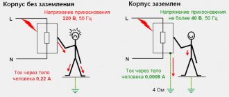
Protective grounding is a deliberate electrical connection to the ground of metal non-current-carrying parts of electrical installations that are not normally energized, but may become energized (primarily due to insulation failure).
When a phase is short-circuited to the metal body of an electrical installation, it acquires electrical potential relative to the ground. If the body of such an electrical installation is touched by a person standing on the ground or a conductive floor (for example, concrete), he will immediately be shocked by an electric shock.
By means of protective grounding, the fault current is redistributed between the grounding device and the person in inverse proportion to their resistances.
Since the resistance of the human body is hundreds of times greater than the resistance to current spreading of the grounding device, a current that does not exceed the maximum permissible value (10 mA) will pass through the body of a person who has touched damaged grounded equipment, and the main part of the current will go into the ground through the grounding loop. In this case, the touch voltage on the equipment housing will not exceed 42 V.
The grounding loop is made of steel rods, angles, substandard pipes, etc. In a trench up to 0.7 m deep, rods (pipes, angles, etc.) are driven vertically, and the upper ends protruding from the ground are connected by overlap welding with a steel strip or rod.
In this case, the following conditions must be observed.
- The cross-section of the connecting strip, its thickness, the minimum diameter of the rod, the minimum wall thickness of the angle are determined in accordance with the technical circular ( ).
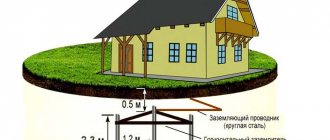
- The length of the rod must be at least 1.5...2 m in order to reach the non-freezing layer of soil (Fig. 2).
Rice. 2. Installation of a single ground electrode in two-layer soil: L - length of a single ground electrode; D is the diameter of a single ground electrode; H—thickness of the top layer of soil; T - depth of the ground electrode (distance from the surface of the earth to the middle of the electrode); t - trench depth (depth of connecting strip)
- It is recommended to choose the distance between adjacent rods equal to the length of the rod (unless otherwise provided by operating conditions) (Fig. 3).
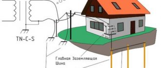
The rods can be placed in a row (Fig. 3) or in the form of any geometric figure (square, rectangle) depending on the ease of installation and the area used. A set of rods connected to each other by a strip forms a grounding loop. In the room, the grounding loop is welded to the body of the power panel and to the grounding line (grounding bus), which runs along the walls of the building. In practice, natural grounding conductors (parts of communications, buildings and structures for industrial or other purposes) that are in contact with the ground are often used. These are sewer pipes, reinforced concrete foundation structures, lead cable sheaths, etc.
Rice. 3. Design of the grounding device: L - length of a single ground electrode; K - distance between adjacent (adjacent) grounding conductors
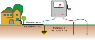
Measurement of resistance to current spreading of grounding devices must be carried out within the time limits established by the Rules for the Operation of Consumer Electrical Installations (RUES) at least once every six years, as well as after each major repair and long-term inactivity of the installation.
It is recommended to measure the resistance of grounding devices on the hottest and driest days of the year, when the soil has the least moisture. The lower the humidity, the higher the soil resistivity. In the first case, moisture from the soil evaporates, in the second it freezes (ice practically does not conduct electricity). When taking measurements on other days, the obtained values must be corrected using correction factors that are given in the PEEP [3].
Calculation of the grounding device comes down to determining the number of vertical grounding rods and the length of the connecting strip. To simplify the calculation, we assume that a single vertical ground electrode is a rod or a small-diameter pipe.
- Resistance of a single vertical ground electrode: (2)
where L and D are the length and diameter of the rod, respectively, m; Peq equivalent soil resistivity, Ohm*m; T - depth of the electrode (distance from the surface of the earth to the middle of the electrode), m.
Students of non-electrical engineering specialties can determine the resistance of a single vertical ground electrode using the formula:
(3)
or using a simplified formula:
(4)
Note: here and below, the sign (*) denotes formulas for calculations carried out by students of non-electrical engineering specialties. Formulas not marked with this sign are common to students of all specialties.
The value of equivalent soil resistivity Peq for students of non-electrical specialties is set by the teacher from the table. 2.
Equivalent soil resistivity Peq with a heterogeneous structure is such a resistivity of the earth with a homogeneous structure, in which the resistance of the grounding device has the same value as in the earth with a heterogeneous structure. If the soil is two-layer, the equivalent resistivity is determined from the expression:
Peq = Y*P1*P2L/[P1(L - H + t) + P2(H - t)], (5)
where Y is the seasonality coefficient (according to Table 2 - for ground rods); P1—resistivity of the top soil layer, Ohm*m; P2—resistivity of the lower soil layer Ohm*m; H—thickness of the top soil layer, m; t — strip depth, m.
A single grounding conductor must completely penetrate the top layer of soil and partially the bottom.
Table 1 - Equivalent soil resistivity
| Priming | Specific resistance Req, Ohm? m | |
| limits of fluctuations | at soil moisture 10…12% | |
| Chernozem | 9…53 | 20 |
| Peat | 9…53 | 20 |
| Clay | 8…70 | 40 |
| Loam | 40…150 | 100 |
| Sandy loam | 150…400 | 300 |
| Sand | 400…700 | 700 |
The depth of the strip t is taken equal to 0.7 m - this is the depth of the trench (Fig. 2). The value of soil resistivity is not constant and depends on its moisture content. The degree of soil moisture is determined mainly by the amount of precipitation and the processes of its drying. Surface layers of soil are subject to significant changes in humidity. As a result, the resistance of the ground electrode will be more stable the deeper it is located in the ground. To reduce the influence of climatic conditions on the grounding resistance, the upper part of the ground electrode is placed in the ground to a depth of at least 0.7 m. Consequently, the depth of the rod can be determined by the formula:
T = (L/2) + t (6)
Table 2 - Values of calculated climatic coefficients of seasonality of soil resistance
| Ground electrode | Climate zone | |||
| I | II | III | IV | |
| Rod | 1,8…2,0 | 1,6…1,8 | 1,4…1,5 | 1,2…1,4 |
| Stripe | 4,5…7,0 | 3,5…4,5 | 2,0…2,5 | 1,5…2,0 |
- We determine the approximate number of vertical grounding conductors without taking into account the resistance of the connecting strip:
n0 = R0/Rн, *(7)
where RH is the normalized resistance to current spreading of the grounding device according to the PUE, Ohm;
For students of electrical engineering specialties:
n0 = R0*Y/Rн.(8)
The seasonality coefficient Y of the second climatic zone (average temperature in January is from -15 to -10°C, in July - from +18 to +22°C) is taken to be 1.6...1.8.
Table 3 - Standardized values of resistance to current spreading of grounding devices (for electrical installations with voltages up to 1000 V)
| Type of grounding | Mains voltage, V | ||
| 220/127 | 380/220 | 660/380 | |
| standardized resistance Rн, Ohm | |||
| Working grounding of the transformer (generator) zero point | 8 | 4 | 2 |
| Re-grounding of the neutral wire at the entrance to the facility | 20 | 10 | 5 |
| Re-grounding the neutral wire on the overhead line | 60 | 30 | 15 |
The values given in table. 3 are valid for equivalent soil resistivity of 100 Ohm*m or less. If the equivalent soil resistivity is more than 100 Ohm*m, these values must be multiplied by the coefficient kз=req/100. The kz coefficient cannot be less than 1 or more than 10 (even with high soil resistivities).
- Determine the current flow resistance of the connecting strip:
(9)
where Lп, b is the length and width of the connecting strip, m; t - depth of the connecting strip; Yп - seasonality coefficient for the strip (according to Table 2 - for strip grounding devices); hp is the bandwidth utilization factor (Table 4).
Formula for approximate calculation:
(10)
The length of the strip can be determined by the preliminary number of vertical ground electrodes. If we assume that they are placed in a row, then the length of the strip will be:
Lп = K(n0 - 1), (11)
where K is the distance between adjacent vertical grounding conductors, m,
- We determine the resistance of vertical grounding conductors taking into account the resistance to current spreading of the connecting strip (for students of electrical engineering specialties):
Rв = Rп*Rн(Rп - Rн) (12).
- We determine the final number of grounding conductors (for students of electrical engineering specialties):
n = Ro/Rв*hс, (13)
where hc is the utilization factor of vertical grounding conductors.
Since currents spreading from parallel-connected single grounding conductors have a mutual influence, the total resistance of the grounding loop increases, which is greater the closer the vertical grounding conductors are located to each other. This phenomenon is taken into account by the utilization coefficient of vertical grounding conductors, the value of which depends on the type and number of single grounding conductors, their geometric dimensions and relative position in the ground.
Table 4 - Usage factors of vertical grounding conductors hс and connecting strip hп
| Number grounding conductors | Grounding electrodes are placed in a row | Grounding electrodes are placed in a closed loop | ||
| h ñ | hï | h ñ | hï | |
| 2 | 0,91 | – | – | – |
| 4 | 0,83 | 0,89 | 0,78 | 0,55 |
| 6 | 0,77 | 0,82 | 0,73 | 0,48 |
| 10 | 0,74 | 0,75 | 0,68 | 0,40 |
| 15 | 0,70 | 0,65 | 0,65 | 0,36 |
| 20 | 0,67 | 0,56 | 0,63 | 0,32 |
| 40 | – | 0,40 | 0,58 | 0,29 |
Note. The values of the coefficients are given taking into account the fact that the ratio of the length of the grounding conductors to the distance between them is equal to two.
- *We determine the resistance of a single ground electrode taking into account the utilization factor:
Rsp = R0/hс.* (14)
- We determine the total resistance of the vertical grounding conductors taking into account the resistance of the connecting strip:
Rв = Rп*Rн/Rп - Rн. (15)
- We determine the final number of grounding conductors:
n = Rsp/Rv. (16)
The calculated number of grounding conductors is rounded to the nearest larger integer.
Based on the calculation data, we draw up a sketch of the grounding loop (plan for placing grounding electrodes in the ground - top view, with dimensions) and a sketch of a single vertical grounding electrode (Fig. 2).
Example of grounding calculation
As a “classical” example of calculating grounding, let’s consider a charger option taking into account the given initial data, that is, we will carry out calculations for a single metal pin. Let us immediately make a reservation that such simple designs are used when organizing the re-grounding of high-voltage supports. In the situation under consideration, according to the provisions of the PUE (see clause 1.7.103.), the current flow resistance cannot be more than 15, 30 and 60 Ohms for voltages of 660, 380 and 220 Volts, respectively.
Calculation of a single grounding element for a 380 Volt overhead line support
According to the previously discussed method, first, using the table, select the type of vertical pin with the following characteristics:
- Material – steel.
- Shape: round rod with a diameter of 16 mm.
- Length L - 2.5 meters.
Please note: Semi-solid clay with a resistivity ρ equal to 60 Ohm per meter is selected as soil in accordance with the table.
The depth of the trench is taken to be half a meter. Then, from the same table, the correction factor entered for the average climatic zone is found. Its value for the actual length of the rods is up to 2.5 meters, taking into account soil freezing in the given area, is ψ = 1.45. The normalized resistance indicator for this type of charger is 30 Ohms. The next indicator, soil resistivity, is found by the formula:
ρ (in fact) = ψ•ρ = 1.45x60 = 87 Ohm•meter
The resulting calculated data looks like this:
- the penetration of a single pin into the ground is h = 0.5l + t = 0.5x2.5 + 0.5 = 1.75 meters;
- its resistance for our example (see formulas above) is no more than 30 Ohms, which corresponds to the requirements of the PUE for a given voltage.
When one grounding pin is not enough to support an overhead line, it is allowed to add one more or even several rods. In this case, a different technique will be required, used for a linear outline or a triangular design.
Grounding of industrial buildings
Calculation of the grounding of an electrical substation is simply necessary; on its territory there is a large amount of equipment operating with high voltage. Therefore, almost all substation equipment (transformers, electrical panels, reinforced concrete and iron machine supports, cable couplings, casings of cable channels and circuit breakers) must be grounded.
The current flow resistance on the objects under consideration should not exceed 0.5 Ohm. To achieve a given figure, when installing substation equipment, they use natural grounding conductors to the maximum, such as pipelines of underground cable channels, metal power transmission poles and support them with cables.
The resistance of such systems is calculated using the formula:
Where:
- R tr — resistance of the cable of one power transmission line support, Ohm;
- R op - resistance to current spreading of the support itself, Ohm.
Grounding of workshop buildings of an industrial enterprise is carried out depending on the availability and quantity of equipment installed in it. The calculation algorithm itself is no different from the example discussed above. Based on the scheme under consideration, the grounding of electrical cables is also calculated.
Qualified specialists from our company will help you make the necessary calculations and draw up a complete package of documentation for grounding the building.
Participation in the calculation formula
In the formula for calculating grounding for a multi-electrode grounding conductor (grounding loop), the utilization factor is in the denominator.
The coefficient for identical vertical grounding conductors has the following values:
- from 1 (i.e. does not affect the grounding resistance) - with a mutual distance between the grounding electrodes equal to their double depth and with a small number of them
- up to 1/N (i.e. additional electrodes do not make any contribution to reducing the grounding resistance) - with a distance between grounding electrodes approaching 1/30 of their depth