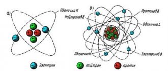
Electricity
Electric current flows through the wires. Moreover, it “flows”, almost like water. Let's imagine that you are a happy farmer who decided to water his garden with a hose. You opened the tap slightly, and water immediately ran through the hose. Slowly, but still she ran.
The jet force is very weak. Then you decided that more pressure was needed and opened the tap to its fullest. As a result, the stream will flow with such force that not a single tomato will be left unattended, although in both cases the diameter of the hose is the same.
Now imagine that you are filling two buckets from two hoses. One of them has stronger pressure, the other weaker. The bucket into which water is poured from a hose with strong pressure will fill faster. The thing is that the volume of water for an equal period of time from two different hoses is also different. In other words, a much larger number of water molecules will run out of the green hose than from the yellow hose in the same period of time.
If we take a conductor with current, the same thing will happen: charged particles will move along the conductor, just like water molecules. If more charged particles move along the conductor, the “pressure” will also increase.
- Electric current is the directed movement of charged particles.
Current strength
There immediately arises a need for a quantity with which we will measure the “pressure” of the electric current. Such that it depends on the number of particles that flow through the conductor.
Current strength is a physical quantity that shows how much charge has passed through a conductor.
How is the current indicated?
The current strength is indicated by the letter I
| Current strength I = q/t I - current strength [A] q - charge [C] t — time [s] |
Current strength is measured in Amperes. The unit of measurement was chosen for a reason.
Firstly, it is named after the physicist André-Marie Ampère, who studied electrical phenomena. And secondly, the unit of this quantity was chosen based on the phenomenon of interaction of two conductors.
Here, unfortunately, it is impossible to draw an analogy with a water supply system. Hoses with water do not attract or repel each other close to each other (which is a pity, it would be funny).
When current flows through two parallel conductors in the same direction, the conductors attract each other. And when in the opposite direction (along the same conductors) they repel.
The unit of current 1 A is taken to be the current at which two parallel conductors 1 m long, located at a distance of 1 m from each other in a vacuum, interact with a force of 0.0000002 N.
Task
Find the current strength in the circuit if a charge equal to 300 mC passes through it in 2 seconds.
Solution:
Let's take the formula for current strength
I = q/t
Let's substitute the values
I = 300 mC / 2 s = 150 mA
Answer: the current in the circuit is 150 mA
D.C
Gentlemen, hello everyone!
Today we will talk about such a fundamental concept of physics in general and electronics in particular as current strength . Each of you has probably heard this term more than once. Today we will try to understand it a little better.
Today we will primarily talk about direct current . That is, about something whose magnitude is constant in strength and direction all the time. Dear gentlemen, bores may begin to dig into the matter - what does “all the time” mean? There is no such term. To this we can answer that the current value should not change throughout the entire observation time.
So, current. Current strength. What is it? Everything is quite simple. Current is the directional movement of charged particles. Please note, gentlemen, that it is directed. The random – thermal – movement, from which electrons in a metal or ions in a liquid/gas rush back and forth, is of little interest to us. But if you superimpose on this random movement the movement of all particles in one direction, then this is a completely different calico.
What kinds of charged particles can there be? In general, it doesn’t matter what it is, it doesn’t matter. Positive ions, negative ions, electrons - it doesn't matter. If we have a directed movement of these respected comrades, it means that there is an electric current.
Obviously, the current has some direction. direction of the current is usually taken to be the movement of positive particles. That is, although the electrons run from minus to plus, it is believed that the direction of the current in this case is the opposite - from plus to minus. This is how everything is twisted. What can you do - a tribute to tradition.
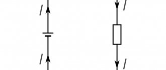
A schematic representation of a current-carrying conductor is shown in Figure 1.
Figure 1 – Schematic representation of a current-carrying conductor
Let's imagine a cloud with mosquitoes. Yes, I know, vile creatures, and the cloud is generally some kind of horror. But still, suppressing disgust, we will try to imagine them. So, in this cloud, every nasty mosquito flies by itself. This is a disorderly movement. Now let’s imagine a saving breeze. He simultaneously carries away this entire horde of mosquitoes in one direction, hopefully away from us. This is a directed movement. Replacing mosquitoes with electrons, and the breeze with some mysterious driving force, we get, in general, some kind of analogy with electric current.
Most often, there is a current caused by the movement of electrons. Yes, friends, throughout our lives we are surrounded by poor little electronics, forced to move directionally, one might say in formation, under the influence of coercive force. They run along power lines, in all our sockets, in all our smart devices - computers, laptops, smartphones and work just like Papa Carlo to make our difficult life easier and fill it with pleasures.
Mosquitoes are mosquitoes, that’s all cool, but it’s time for formal definitions.
So, gentlemen, the current strength is the ratio of the charge Δq, which is transferred through a certain cross-section of the conductor S during the time ∆t. Current strength is measured, as many already know, in Amperes. So - the current in a conductor is equal to 1 Ampere if 1 Coulomb passes through this conductor in 1 second.
"Great!" - the dear reader will exclaim. And what should I do with this formula?!! Well, okay, I have a stopwatch on my iPhone, I’ll time it. What about the charge? Should I count the number of electrons in the wire and then multiply by the charge of one electron, fortunately this is a known quantity, in order to determine the current?!
Calm, gentlemen! All will be. Do not hurry. For now, just remember that there was some kind of formula. Then it turns out that with its help you can calculate some cool things like charging capacitors and much more.
Well, for now... For now, you can take an ammeter, measure the current in the circuit with a light bulb and find out what charge flows every second through the cross-section of the conductor q = I t = I 1c = I.
Yes, every second a charge equal to the current in it flows through a cross-section of a conductor. You can now multiply this value by the charge of the electron (for those who have forgotten, I remind you that it is equal) and find out how many electrons are running in the circuit. Questions may arise - what for? The author's answer is just for fun. You are unlikely to get any practical benefit out of this. If only you please your teacher. This problem is purely academic.
The question may arise - how does an ammeter measure current? Is he counting electrons? Of course not, gentlemen. Here we have indirect measurements. They are based on the magnetic action of current in old-fashioned analog dial ammeters or on Ohm's law - by converting the flowing current through a known resistance into voltage and its subsequent processing - in all modern multimeters. But more on that later.
Now, just for fun, let’s estimate the speed at which electrons move directionally in a conductor . Wait to read further. Slow down. What do you think the speed might be? At least the order of the numbers? To be honest, when, as a green student just starting to get a taste of physics, our old teacher asked us this question, figures close to the speed of light appeared in my head. I was sure that electrons move in conductors not just quickly, but very quickly. Therefore, the calculation results shocked me a little.
Now I will give this calculation. It is quite simple and should be digested even by humanists. If you have an individual intolerance to matan, well, you can just look at the result.
Let's remember about our charge ∆q , which passes in time ∆t through the cross section of the conductor ∆S , which we talked about just above. Like true mathematicians, we will complicate it to the point of outrageousness, so that only after straining the brain it will be clear that we have written an identity.
Gentlemen, honestly, no deception. e is the charge of an electron, n is the concentration of electrons, that is, the number of pieces in one cubic meter, v is the speed of electron movement. It is obvious that v∙∆t∙∆S is essentially the volume that the electrons will pass through. We multiply the concentration by the volume - we get pieces, how many pieces of electrons have passed. We multiply the pieces by the charge of one electron - we get the total charge passing through the cross section. I told you everything was fair!
Let us introduce the concept of current density. Bores who have already read something about this will now exclaim - yeah, this is a vector quantity! I don’t argue, gentlemen, it’s vector. But to simplify an already difficult life, we will assume that the direction of the current density vector coincides with the axis of the conductor, which is what happens in most cases. Therefore, vectors immediately become scalars. Roughly speaking, current density is how many amperes are per square meter of conductor cross-section. Obviously, to do this, you need to divide the current by the area. We have
Now, I hope, it’s clear why we transformed the formula this way? To cut down on a bunch of stuff!
We remember the main thing - we are looking for speed. Let's express it:
Everything would be fine, but we don’t know the concentration yet. Let's remember chemistry. There was such a formula
Where ρ=8900 kg/m3 is the density of copper, NA=6·1023 Avogadro’s number, M=0.0635 kg/mol is the molar mass.
Gentlemen, I hope there will be no need to explain where this formula came from. I'm not very good with chemistry, to be honest. Although I studied at school for 11 years with an in-depth study of chemistry, however, in the 8th grade I entered a physics and mathematics class, became interested in physics, especially the part that talks about electricity, and, one might say, gave up on chemistry. Actually, they didn’t ask us deeply about it; we were physicists. However, if the need suddenly arises, I am still ready to delve into this chemical jungle and tell you what’s what.
Thus, the speed of movement of electrons in a conductor with current is equal to
Let's substitute specific numbers. For definiteness, let us set a current density of 5 A/mm2.
We already have all the other numbers. The question may arise - why exactly 5 A/mm2.
It's simple, gentlemen. This is not the first time that people have been involved in electronics. Some experience has been accumulated in this area, or, in scientific terms, empirical data. So, these empirical data say that the permissible current density in copper wires is usually 5-10 A/mm2 . At higher current densities, unacceptable overheating of the conductor is possible. However, for tracks on a printed circuit board this value is much higher and amounts to 20 A/mm2 or even more. However, this is a topic for a completely different conversation. Let's return to our task, namely, calculating the speed of electrons in a conductor. Substituting the numbers, we get that
Gentlemen, the calculation irrefutably shows that electrons in a current-carrying conductor move at only a speed of 0.37 millimeters per second! So slow. However, it should be remembered that this is not thermal movement, but directional. The thermal movement is much, much greater, on the order of 100 km/s. A reasonable question - why does the light flash instantly when I turn the switch? Remember what I said about some kind of coercive force? It's about her! But more on this in the next article. Great good luck to you all, and see you again!
Join our VKontakte group
Questions and suggestions to the admin: This email address is being protected from spambots. You need JavaScript enabled to view it.
Social button for Joomla
Current formula
The formula for dummies will look like this:
Where
I - actual current strength, Amperes
N - number of electrons
t is the period of time during which these electrons travel through the cross section of the conductor, seconds
The more correct (official) formula looks like this:
Where
Δq is the charge over a certain period of time, Coulomb
Δt — the same period of time, seconds
I - current, Amperes
What's so funny about these two formulas? The thing is that an electron has a charge of approximately 1.6 10-19 Coulomb. Therefore, for the current strength in the wire (conductor) to be 1 Ampere, we need a charge of 1 Coulomb = 6.24151⋅1018 electrons to pass through the cross section. 1 Coulomb = 1 Ampere · 1 second.
So, now we can officially say that if 6.24151⋅1018 electrons fly through the cross-section of a conductor in 1 second, then the current strength in such a conductor will be equal to 1 Ampere! All! There is no need to invent anything else! Tell your physics teacher so.)
If the teacher doesn’t like your answer, then say something like this:
Current strength is a physical quantity equal to the ratio of the amount of charge passing through the surface (read as through the cross-sectional area) over some time. Measured as Coulomb/second. To save time and according to other moral and aesthetic standards, they agreed to call the coulomb/second Ampere, in honor of the French physicist.
Basic concepts of Ohm's law
How to understand Ohm's law? You just need to figure out what is what in its definition. And you should start by determining the current, voltage and resistance.
Current strength I
Let a current flow in some conductor. That is, there is a directed movement of charged particles - for example, these are electrons. Each electron has an elementary electric charge (e= -1.60217662 × 10⁻¹⁹ Coulombs). In this case, a specific electric charge equal to the sum of all charges of flowing electrons will pass through a certain surface in a certain period of time.
The ratio of charge to time is called current strength. The more charge passes through a conductor in a certain time, the greater the current. Current strength is measured in Amperes .
Voltage U, or potential difference
This is exactly the thing that makes electrons move. Electric potential characterizes the ability of a field to do work to transfer charge from one point to another. So, between two points of a conductor there is a potential difference, and the electric field does work to transfer charge.
A physical quantity equal to the work of the effective electric field during the transfer of electric charge is called voltage. Measured in Volts . One Volt is the voltage that, when moving a charge of 1 C , does work equal to 1 Joule .
Resistance R
Current, as we know, flows in a conductor. Let it be some kind of wire. Moving along a wire under the influence of a field, electrons collide with atoms of the wire, the conductor heats up, and the atoms in the crystal lattice begin to vibrate, creating even more problems for the electrons to move. This phenomenon is called resistance. It depends on temperature, material, conductor cross-section and is measured in Ohms .
Monument to Georg Simon Ohm
Current strength and resistance
Let's take another look at the water hose and ask ourselves questions. What does water flow depend on? The first thing that comes to mind is pressure. Why do the water molecules move from left to right in the picture below? Because the pressure on the left is greater than on the right. The greater the pressure, the faster the water will flow through the hose - this is elementary.
Now the question is: how can we increase the number of electrons across the cross-sectional area?
The first thing that comes to mind is to increase the pressure. In this case, the speed of water flow will increase, but you won’t increase it much, since the hose will break like a hot water bottle in Tuzik’s mouth.
The second is to install a hose with a larger diameter. In this case, we will have more water molecules passing through the cross section than in a thin hose:
All the same conclusions can be applied to an ordinary wire. The larger its diameter, the more current it can “pull” through itself. The smaller the diameter, it is advisable to load it less, otherwise it will “tear”, that is, it will burn out stupidly. This is the principle behind fuses. There is a thin wire inside such a fuse. Its thickness depends on the current strength it is designed for.
fuse
As soon as the current through the thin fuse wire exceeds the current for which the fuse is designed, the fuse wire burns out and opens the circuit. Current can no longer flow through a blown fuse, since the wiring in the fuse is broken.
burnt fuse
Therefore, power cables, through which hundreds and thousands of amperes “run,” are taken with a large diameter and try to be made of copper, since its resistivity is very low.
How to measure current?
In order to measure the value of current, we must use special devices - ammeters. Currently, current can be measured using a digital multimeter, which can measure current, voltage, resistance and much more. In order to measure the current, we must insert our device into the open circuit like this.
You can read more details on how to do this in this article.
I also advise you to watch a training video where a very smart teacher explains in simple language what “current strength” is.
Basic units of current
The basic unit of current measurement is the ampere (short symbol: A). Ampere, named after the physicist Henri Ampere, is included in the International System of Units (SI).
If 1 coulomb of electricity passes through a cross section within 1 second, then the current in that conductor is equal to one ampere. How auxiliary units are used:
- milliamps (ma), one thousandth or 10-3 amperes;
- microamps (µA), one millionth or 10-6 amperes.
Current strength is an important parameter, knowledge of which will help in choosing cables with the optimal cross-sectional size for the planned load.
Current strength - designation and basic formulas
In formulas when calculating such a parameter as current strength, the designation of its value using the letter “I” is generally accepted. The basic formula looks like I=q/t, where q is the amount of electricity, and t is the time period.
You can also use parameters such as:
- actual voltage (U);
- power (P).
In this case, the formula I= P/U is applied. Obtaining current strength by calculation is relevant in cases where the use of measuring instruments is impossible, for example, at the stage of designing electrical networks.
Basic concepts and formulas characterizing electric current
The quantitative parameter of an electric current is its strength, which is a scalar quantity and is expressed in the ratio of the charge (usually denoted by the letter q ) to the time period ( t ) during which it crosses the cross-section of the conductor. Consequently, the formula for electric current, and if we speak correctly its strength, will look like this - I=q/t . This parameter is measured in amperes. Since scalar quantities are real numbers and are defined only by value, current cannot have a negative sign. Taking into account the fact that the amount of charge is not a constant parameter for different electrical circuits, the concept was introduced - electric current density ( j ), the formula of which looks like this - j=I/S , where S is the area crossed by the charges. Consequently, as the current increases and the cross-section of the conductor decreases, the current density increases and vice versa. As noted above, important parameters of electricity, or rather of an electrical circuit, are the voltage in it and the resistance of the current-conducting elements.
Formula for expressing the strength of electric current through resistance and voltage
Unlike fundamental research, which is based on theoretical calculations, this dependence was derived in a practical way. The author of the discovery is the physicist Ohm, in whose honor the law received its name. Based on the results of his experiments and experiments, Ohm came to the conclusion that the current strength ( I ) directly depends on the voltage ( U ) and has an inverse relationship with the resistance ( R ) of the elements and parts included in the electrical circuit. This relationship can be represented as – I=U/R . Through simple transformations, the formulas for resistance and voltage, expressed in terms of current, will look like this - R=U/I and U=IxR , respectively.
Electric current formula
Electric current resistance: formula
Electric current voltage formula
Examples of typical currents
Current values can be read on information plates on electrical receivers or in the manuals for these devices. The table below shows typical values of electric currents for various electrical receivers.
| Consumer | Current strength |
| Electric thermometer | about 0.00001 mA |
| Headphones | 1 mA |
| Incandescent lamp 60 W | 0.26 A |
| Incandescent lamp 75 W | 0.33 A |
| Fridge | 0.8 A |
| Smartphone charger (fast charging) | 2 A |
| Personal Computer | 0.87 - 2.6 A |
| Microwave | 3.5 A |
| Vacuum cleaner | 4 - 9 A |
| Washing machine | 6 - 10 A |
| Electric melting furnace | 15000 A |
| Thunderstorm lightning | 10,000 - 100,000 A (average 36,000 A) |
Instruments for measuring current strength
An instrument for measuring current strength is called an ammeter, in addition to the topic of how current is measured. It can be pointer, digital and electronic. It is actively used in electrical laboratories, automotive industry, exact science and construction. According to the operating principle, it can be electromagnetic, magnetoelectric, thermionic, ferrodynamic, electrodynamic and digital. Measures both alternating and direct current.
It works due to the interaction of a magnetic field with a moving coil or core, which is located in the housing. All types are very easy to use. All the user needs to do is carefully study the instructions and operating instructions. As a rule, to start measuring, you need to touch the conductor using probes and press the corresponding button. Afterwards, the value in amperes will be displayed on the screen. It is worth pointing out that a voltmeter, a multimeter and a measuring screwdriver also measure current strength.
Ammeter
Electric current measurement
Electric current is measured by ammeters. Multifunctional electrical measuring instruments are also often used, for example, multimeters, which can also be switched to the mode of measuring electric current and work as ammeters.
Ammeters are always connected in series to the consumer in which the current is measured. This means that the current through the consumer will correspond to the current through the ammeter.
In order to determine the current strength in this way, it is necessary to break the electrical circuit at the measurement location and insert an ammeter.
The ammeter is connected to the circuit using two terminals, or clamps, located on the device. One of the ammeter terminals, as a rule, has a “+” sign, the other “-” (sometimes there is no “-” sign). The terminal with the “+” sign must be connected to the wire coming from the positive pole of the current source.
Since the ammeter also has internal resistance, it affects the electrical circuit during measurement. However, the resistance of an ammeter is usually so small that it can be neglected.
Figure 1 shows such a series connection using the example of a light bulb and an ammeter.
Current measurement
If you do not want to interfere with the electrical circuit by disconnecting the conductors, then the electrical current can also be measured indirectly using a current clamp. Another option is to measure the voltage across the consumer, and then, knowing the electrical resistance of the consumer, calculate the current using Ohm's law.
What does current depend on?
Since the current force is a scalar quantity that has a positive and negative charge, it depends on the power of the charge, the concentration of particles concentrated in the charge, the speed of their movement and the area of the conductor. It is also worth pointing out that it depends on the resistance value with voltage, magnetic field strength, number of coil turns, rotor power, conductor diameter and generator set parameter.
Dependence of electric current on resistance and voltage
Current source
To maintain electric current in the circuit, it is necessary that at its ends (Fig. 2) there is a constant potential difference φ1 – φ2. Let at the initial moment of time φ1 > φ2, then the transfer of positive charge q
from the source terminal “+” to the “–” terminal will lead to a decrease in the potential difference between them.
To maintain a constant potential difference, it is necessary to transfer exactly the same charge from the “–” terminal to the “+” terminal. If in the direction from “+” to “–” positive charges move under the influence of Coulomb forces Fk
, then in the direction from “–” to “+” the movement of charges occurs against the direction of action of Coulomb forces, i.e.
under the influence of another force F
st, which is called an external force.
Rice. 2
- Third-party forces
are any forces acting on electrically charged particles, with the exception of electrostatic (Coulomb) forces.
External forces arise in the current source.
- A current source
is a device capable of maintaining a potential difference between the ends of an electrical circuit and ensuring the orderly movement of electrical charges in an external circuit.
Sources of electric current may vary in design, but in any of them work is done to separate positively and negatively charged particles. The separation of charges occurs under the influence of external forces. We list the most common current sources:
- galvanic cells
(batteries) (Fig. 3, a) and
accumulators
- third-party forces use the energy of chemical reactions; - generators
(dynamos) - third-party forces use the mechanical energy of falling water, wind, steam, etc.; - photocells
(solar batteries) (Fig. 3, b) - external forces use the energy of electromagnetic radiation (light).
- A
- b
Rice.
3 The source of electric current has two poles (two terminals) to which the ends of the wires are connected.
The conductor connecting the terminals of the source from the outside is called the external section of the circuit
.
The resistance of this source is denoted by R
and is called
external resistance
.
Inside the source itself, charges move along the internal section of the circuit
.
The source resistance is denoted by r
and is called
internal resistance
.
The sum of external and internal resistances ( R + r
) is called
the total resistance of the circuit
.
On electrical diagrams, the current source is designated as shown in Fig. 4. The positive pole (terminal) of the source is conventionally represented by a longer line than the negative one.
Rice. 4
Any current source is characterized by electromotive force - EMF.
- EMF (Electromotive force) ε of a current source is a physical scalar quantity that is numerically equal to the work of external forces Ast
to move a single positive charge inside the current source:
\(~\varepsilon = \dfrac{A_{st}}{q} .\)
The SI unit of electromotive force is the volt (V).
EMF is an energy characteristic of a current source.
- The term “ electric motor force
” was introduced by Ampere in 1822. The abbreviation EMF is usually read without decoding.
see also
All about chemical current sources
What are the types of electric current in everyday life?
The shape of the current signal depends on the operation of the voltage source and the resistance of the medium through which the signal passes. Most often in practice, a home craftsman has to deal with the following types:
- a constant signal generated from batteries or galvanic cells;
- sinusoidal, created by industrial generators with a frequency of 50 hertz;
- pulsating, formed by transformations of various power supplies;
- pulsed, penetrating into the household network due to lightning discharges into overhead power lines;
- arbitrary.
The most common type is sinusoidal or alternating current: it powers all our devices.
Many semiconductor household appliances operate in modern wiring powered by sinusoidal voltage. They have non-linear resistance and violate the harmonic shape.
These noises accumulate throughout the entire circuit from a specific consumer to the supply transformer, distorting the ideal sine wave in an arbitrary manner. As a result, both the shape and magnitude of the supply voltage changes.
Current strength in a metal conductor: how it is used in domestic conditions
The ability of the internal structure of metals to differently influence the conditions of movement of directed charges is used to implement specific tasks.
To transmit electrical energy over long distances, metal conductors of increased cross-section with high conductivity are used: copper or aluminum. The more expensive metals silver and gold work inside complex electronic circuits.
All kinds of designs of wires, cords and cables based on them are reliably used in home wiring.
Tungsten and nichrome, which have high resistance, are used for heating devices. It allows the conductor to be heated to high temperatures with the correct selection of applied power.
This principle is embodied in numerous designs of electric heaters - heating elements.
The increased current strength in a metal conductor with good conductivity but a thin cross-section makes it possible to create fuses used as current protection.
They work normally under optimal load conditions, but quickly burn out during voltage surges, short circuits or overloads.
For several decades, fuses massively served as the main protection for home wiring. They have now been replaced with circuit breakers. But inside all power supplies they continue to work reliably.
Current in semiconductors and its characteristics
The electrical properties of semiconductors strongly depend on external conditions: temperature, light irradiation. To increase their own conductivity, special impurities are added to the structure.
Therefore, inside the semiconductor, the current is created due to the intrinsic and impurity conductivity of the internal pn junction. The charge carriers of a semiconductor are electrons and holes. If the positive potential of the voltage source is applied to pole p, and the negative potential to pole n, then current will flow through the pn junction due to the movement they create.
When the polarity is applied in reverse, the pn junction remains closed. Therefore, in the picture above, in the first case, a light bulb is shown, and in the second, an extinguished one.
Similar pn junctions work in other semiconductor designs: transistors, zener diodes, thyristors...
All of them are designed to carry rated current. To do this, markings are applied directly to their body. Using it, they enter the tables of technical reference books and evaluate the semiconductor based on its electrical characteristics.
Example of calculating current strength for different connections
For example, let's take a circuit with parallel connection of two branches with identical resistors. The ammeter shows that the current strength in each branch is the same - 0.5 Ampere (A). The value of the current a little further from the junction of the branches will be equal to unity, i.e. are summed up:
0.5 + 0.5 = 1 A.
Let's measure the current in a series connection. At any point in the circuit, the ammeter will show the same value (0.5 A), regardless of the number of resistors and their resistance:
0.5 = 0.5 = 0.5 A.
Series connection of resistors.
Let's start by looking at circuits whose elements are connected in series. And although we will only consider resistors as circuit elements in this article, the rules regarding voltages and currents for different connections will also be valid for other elements. So, the first circuit that we will disassemble looks like this:
Here we have a classic case of a series connection - two resistors connected in series. But let’s not get ahead of ourselves and calculate the total resistance of the circuit, but first consider all the voltages and currents. So, the first rule is that the currents flowing through all conductors in a series connection are equal to each other:
I = I_1 = I_2
And to determine the total voltage in a series connection, the voltages on the individual elements must be summed up:
U = U_1 + U_2
At the same time, according to Ohm’s law, the following relationships hold true for voltages, resistances and currents in a given circuit:
U_1 = I_1R_1 = IR_1U_2 = I_2R_2 = IR_2
Then the following expression can be used to calculate the total voltage:
U = U_1 + U_2 = IR_2 + IR_2 = I(R_1 + R_2)
But Ohm’s law is also valid for general voltage:
U = IR_0
Here R_0 is the total resistance of the circuit, which, based on two formulas for the total voltage, is equal to:
R_0 = R_1 + R_2
Thus, when resistors are connected in series, the total resistance of the circuit will be equal to the sum of the resistances of all conductors.
For example for the following circuit:
The total resistance will be equal to:
R_0 = R_1 + R_2 + R_3 + R_4 + R_5 + R_6 + R_7 + R_8 + R_9 + R_{10}
The number of elements does not matter, the rule by which we determine the total resistance will work in any case. And if in a series connection all resistances are equal (R_1 = R_2 = ... = R), then the total resistance of the circuit will be:
R_0 = nR
In this formula, n is equal to the number of elements in the chain. We've figured out the series connection of resistors, let's move on to parallel.
Kirchhoff's laws
Some call them rules because they do not represent the fundamental laws of physics. However, in electrical engineering they can be considered as basic. Kirchhoff's first rule is a consequence of the law of conservation of charge and states that at any point in an electrical circuit the algebraic sum of currents is zero.
If we consider a point lying inside a branch of the circuit, then the statement about the equality of the incoming and outgoing currents becomes valid. Where three or more branches converge, Kirchhoff's law allows one to construct equations that can be used to determine the various characteristics of electrical circuits. This law is one of the manifestations of the law of conservation of energy. It must always be taken into account that the current cannot change abruptly at any point. The situation when it appears out of nowhere or disappears into nowhere is excluded by Kirchhoff's first law.
A simple electrical circuit consists of a current source, its consumer, for example, a light bulb, and the wires connecting them. Real circuits are much more complex, but each of them is subject to the laws of electrical engineering. In particular, the circuit may contain numerous branches and closed internal loops. Kirchhoff's second law states that the sum of the voltage drops when bypassing the circuit is equal to the sum of the EMF of the current sources present in it.
Through charge and time
electricity is the amount of charge driven by the forces of an electric field that overcomes the conventional plane of a conductor, called the cross-section of the conductor, per unit time.
Definition of current strength
Thus, if the electric charge passed through a conductor in a certain time is known, then it is not difficult to find the value of this charge passed per unit time, that is: I = q/t
What is voltage and current?
By the way, what exactly are electric current and voltage? I think that no one really knows, because to know it you have to at least see it. Who can see the current running through the wires?
Yes, no one, humanity has not yet achieved such technologies to personally observe the movements of electric charges. All that we see in textbooks and scientific works is some kind of abstraction created as a result of numerous observations.
Well, okay, we can talk a lot about this... So let's try to figure out what electric current and voltage are. I will not write definitions; definitions do not give the very understanding of the essence. If interested, take any physics textbook.
Since we do not see the electric current and all the processes occurring in the conductor, then we will try to create an analogy.
And traditionally, the electric current flowing in a conductor is compared to water running through pipes. In our analogy, water is an electric current. Water runs through the pipes at a certain speed, the speed is the current strength, measured in amperes. Well, pipes are a conductor in themselves.
Okay, we imagined electric current, but what is voltage? Let's help now.
The water in the pipe, in the absence of any forces (gravity, pressure), will not flow; it will rest like any other liquid poured onto the floor. So this force, or more precisely, energy in our plumbing analogy, will be the same tension.
But what happens to the water running from a reservoir located high above the ground? Water rushes in a stormy stream from the reservoir to the surface of the earth, driven by gravitational forces. And the higher the reservoir is located from the ground, the faster the water flows out of the hose. Do you understand what I'm talking about?
The higher the tank, the greater the force (read voltage) acting on the water. And the greater the speed of the water flow (read current strength). Now it becomes clear and a colorful picture begins to form in my head.
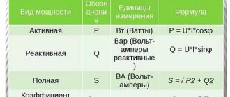
Work and power of electric current
The formula for the power ( P ) of an electric current directly depends on its work ( A ). The work of current means the transformation of electrical energy into mechanical, thermal, light or another form. The magnitude of this process directly depends on the time it occurs, the current strength and voltage in the network. This can be expressed by the following formula - A = IxUxt . The product ( IxU ) is nothing more than the power. Consequently, the higher the voltage or current in the network, the greater the power of the electric current and the more work it can do per unit of time. The formula for electric current power is as follows: P=A/t or P=IxU .
Work of electric current formula
Electric current power formula
Therefore, if it is necessary to calculate how much work is produced by a current flowing through a circuit for a certain time, it is necessary to multiply the power by the time period expressed in seconds. Let's consider the use of formulas for calculating the work and power of electric current using the example of an electric motor connected to a 220 V network, and the current measured by an ammeter for this section was 10A.
P (motor power) = 10A (current) x 220V (mains voltage) = 2200 W = 2.2 kW.
Knowing this indicator, as well as the real or estimated operating time of the electric motor, you can determine what work it will do during this period of time, or in other words, how much electricity will be spent. If the engine was turned on, for example, 1 hour, then you can find the desired value.
A (work done by the engine) = 2.2 kW (power) x 1 (operating time in hours) = 2.2 kWh. It is this indicator that will be reflected on the electricity consumption meter.
Based on the fact that electric current is a physical process, any of its unknown parameters can be determined by knowing its other characteristics. We present the most common formulas for determining the characteristics of an electrical circuit used in electrical engineering.
Voltage or potential difference
- U = RxI
- U = P/I
- U = (P*R)1/2
Electric current strength
- I=U/R
- I = (P / R)1/2
Resistance
- R=U/I
- R = U2/P
- R = P / I2
What is EMF: explanation in simple words
EMF is understood as the specific work of external forces to move a unit charge in an electrical circuit. This concept in electricity involves many physical interpretations related to various areas of technical knowledge. In electrical engineering, this is the specific work of external forces that appears in inductive windings when an alternating field is induced in them. In chemistry, it means the potential difference that occurs during electrolysis, as well as during reactions accompanied by the separation of electrical charges.
In physics, it corresponds to the electromotive force created at the ends of an electrical thermocouple, for example. To explain the essence of EMF in simple words, you will need to consider each of the options for its interpretation. Before moving on to the main part of the article, we note that EMF and voltage are very similar concepts in meaning, but they are still somewhat different. In short, the EMF is on the power source without a load, and when a load is connected to it, it is already a voltage. Because the number of volts on the power supply under load is almost always slightly less than without it. This is due to the internal resistance of power sources such as transformers and galvanic cells.
Electromotive force (emf), a physical quantity characterizing the action of third-party (non-potential) forces in direct or alternating current sources; in a closed conducting circuit is equal to the work of these forces to move a single positive charge along the circuit. If we denote the field strength of external forces by Etr, then the emf in a closed loop (L) is equal to , where dl is the element of the loop length. The potential forces of an electrostatic (or stationary) field cannot maintain a constant current in the circuit, since the work of these forces on a closed path is zero. The passage of current through the conductors is accompanied by the release of energy - heating of the conductors.
Third-party forces set in motion charged particles inside current sources: generators, galvanic cells, batteries, etc. The origin of third-party forces can be different. In generators, external forces are forces from the vortex electric field that arises when the magnetic field changes over time, or the Lorentz force acting from the magnetic field on electrons in a moving conductor; in galvanic cells and batteries - these are chemical forces, etc. Emf determines the current strength in the circuit at a given resistance (see Ohm's law). EMF, like voltage, is measured in volts.
What is EMF.
Basic formulas and guidelines for solving problems on the laws of direct current
"In order to improve the mind,
you need to reason more than memorize.”
Rene Descartes
This topic is devoted to the basic formulas and methodological recommendations for solving problems on the laws of direct current
Direct
current
is an electric current that does not change its direction over time.
There are a number of laws and rules that apply to this type of current - these are the laws of direct current
.
So what is electric current?
Electric current
is the ordered movement of charged particles.
When charged particles move in the same direction in a conductor, a direct current occurs. There are various types of electrical circuits for which the laws of direct current are applied. The strength of the current
is determined by the speed of passage of the charge through the cross-section of the conductor, that is, the strength of the current can be calculated from the ratio of the charge to the period of time during which this charge passed through the cross-section.
Another important characteristic is electrical voltage
.
In an electrical circuit, the voltage
between two points is a physical quantity, the value of which is equal to the ratio of the work of the electric field performed when transferring a test electric charge from one point to another, to the value of the test charge.
Similar to resistance forces in mechanics, there is also electrical resistance. This value characterizes the properties of a conductor to prevent the flow of electric current. Resistance
is defined as the ratio of the voltage between two points on a conductor to the current flowing through that conductor.
For current to flow through an electrical circuit, first of all, you need a current source. The main characteristic of a current source is electromotive force
.
This value characterizes the work of external forces acting in the electrical circuit. Third-party forces
, in this case, are forces of non-electrical origin, since they do work to separate charges to maintain voltage in the electrical circuit.
Let's tabulate the basic formulas of the laws of direct current
| Formula | Description of the formula |
| Current strength I in a section of the circuit is directly proportional to the voltage | |
| Current strength in the conductor, where q is the transferred charge, and | |
| Current strength in a closed circuit operating from a current source with EMF, where R is the circuit resistance, | |
| EMF of the source, where A st – work of external forces to move charge | |
| EMF of a circuit with several current sources connected in series. The sign of the EMF of a particular source is determined in accordance with the direction of the current bypass. | |
| The voltage on a section of a circuit with several elements connected in series, where Ui – voltage on a specific element. | |
| The strength of the current passing through series-connected circuit elements. | |
| Resistance in a section of a circuit with several elements connected in series, where Ri – resistance of a specific element. | |
| The electrical capacity of a system of series-connected capacitors, where Ci – the capacity of a specific capacitor. | |
| Current strength with parallel connected elements, where II – current in a specific element. | |
| The voltage across each of the circuit elements connected in parallel. | |
| Calculation of the resistance of a circuit section with several elements connected in parallel. | |
| Capacitance of a system of parallel connected capacitors. | |
| Work of electric current I at voltage | |
| The amount of heat released as a result of the flow of electric current through a conductor. | |
| Electric current power I at | |
| Conductor resistance length l and cross-sectional area | |
| Dependence of conductor resistance on temperature, where R 0 – conductor resistance at a temperature of 0ºС, |
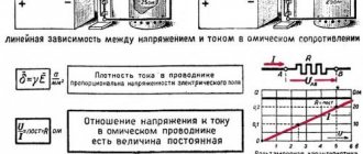
As can be seen from the last function, the resistance depends linearly on temperature, so the corresponding graph is a straight line. However, it should be noted that this dependence is only true for conductors: semiconductors behave completely differently, and as the temperature increases, their resistance, on the contrary, decreases.
Also, it should be noted that a single conductor may have its own current-voltage characteristic (that is, the dependence of current on voltage). To determine it, a conductor is connected to the circuit, and an ammeter and a voltmeter are connected to it to make the appropriate measurements. For example, the graph shows the current-voltage characteristic of a conductor in which the current strength is proportional to the square of the voltage.
Methodological recommendations for solving problems on the laws of direct current
1. Draw a diagram of the electrical circuit described in the problem, indicating on it all the necessary quantities.
2. Derive relationships between quantities using the rules of serial and parallel connection.
3. If necessary, apply Ohm's law for a section of a circuit or for a complete circuit.
4. If necessary, draw a simplified equivalent circuit diagram.
5. If necessary, consider the work or power generated by one or another element of the circuit.
6. Based on the applied laws and rules, create a system of equations and solve it relative to the required quantities.
7. Carry out the necessary calculations and write down the results as an answer.