Diodes are widely used in almost all electrical appliances. And they perform such functions as protecting equipment from overloads, protection from incorrect polarity connections, breakdown when devices are turned off, AC rectification, signal detection and many other functions. Therefore, you need to know how diodes are correctly marked and how to choose them correctly.
Definition of a diode and its types
A diode is an electronic part consisting of two electrodes. Depending on the polarity of the voltage, its conductivity changes. According to the current-voltage characteristic, the diode is nonlinear and asymmetrical. This distinguishes it from an incandescent lamp and a thermistor.
The diode consists of:
- vacuum glass, ceramic or metal flask
- cathode, creating electron emission
- anode for receiving electrical carriers
- heating filament
- germanium or silicon crystal
Based on their structure and properties, diodes are divided into:
- planar
- universal
- pulse
- rectifier
A separate category includes LEDs, photodiodes and thyristors.
There are electric vacuum and gas-filled diodes, discharge stabilizing devices and semiconductors. The latter type is most common in electrical engineering.
I-V characteristics of rectifier diodes (Ge, Si)
The current-voltage characteristics of diodes are graphs of forward and reverse currents (Y) and voltages (X) at different temperatures.
When a reverse voltage is applied that exceeds the threshold value, the reverse current increases and a breakdown of the pn layer occurs. It is worth paying attention to the orders of numbers along the axes. The magnitude of the reverse current is an order of magnitude smaller than the forward current. The forward voltage values are an order of magnitude lower than the reverse voltage. Upon reaching the threshold value of the forward voltage, the forward current begins to increase like an avalanche.
The difference between the diodes is that the reverse current of silicon diodes is less than that of germanium diodes. Therefore, due to the higher current, in Ge diodes the breakdown is thermal in nature, while in Si diodes the electrical breakdown predominates. The power dissipated at the same currents is less for germanium diodes.
Ohm's law in electrical engineering
Diode manufacturing materials
Gallium arsenide, selenium, silicon, germanium, and indium phosphide are used in the production of diodes. The most common diodes are made of germanium, silicon and gallium arsenide.
Features of diodes made of different materials
Germanium diodes are among the most expensive. Possessing low voltage, they have high conductivity. The bias voltage of such devices is 0.3 V. They are used in low-power circuits when silicon diodes cannot cope with the task. Silicon diodes are the most common. Bias voltage – 0.7 V.
Diodes made from gallium and arsenic have a highly intense electric field. Even at high power, the devices are resistant to radiation.
Diode junction area
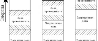
The right layer of the diode (p) has hole conductivity, and the left one (n) conducts negative electrons through itself. When the holes on the right side change their position, a current is generated. When layers of different conductivities touch each other, holes move to the left side of the diode, and electrons move to the right. A positive charge is formed in the border zone on the left side, and negative charges are formed on the border on the right side.
Based on the size of the junction, diodes are divided into:
- planar;
- point;
- microalloy
The first type is distinguished by the shape of the plate, in which both zones are endowed with impurity conductivity. The latter have a small area for the movement of weak current. The third type combines single crystals.
Planar diodes
Point diodes
Microalloy diode
An electric field is formed between the boundaries of the p and n regions. It is a barrier of current carriers with a region of minimum charge concentration. When the direction of the electric field outside changes, the barriers change and the resistance of the electric currents increases. In this case, the transitions are endowed with gate characteristics.
Methods for determining polarity
To determine the polarity of a diode product, you can use various techniques, each of which is suitable for certain situations and will be considered separately. These methods are divided into the following groups:
- A visual inspection method that allows you to determine the polarity based on existing markings or characteristic features;
- Checking with a multimeter turned on in dialing mode;
- Finding out where is the plus and where is the minus by assembling a simple circuit with a miniature light bulb.
Battery polarity
Let's consider each of the listed approaches separately.
Visual inspection
This method allows you to decipher the polarity using special marks on the semiconductor product. For some diodes this may be a point or an annular strip shifted towards the anode. Some samples of the old brand (KD226, for example) have a characteristic shape, pointed on one side, which corresponds to a plus. On the other, completely flat end, there is a minus, respectively.
Note! When visually examining LEDs, for example, it is discovered that one of their legs has a characteristic protrusion.
Based on this feature, it is usually determined where such a diode has a plus and where the opposite contact is.
Application of the measuring instrument
The simplest and most reliable way to determine polarity is to use a multimeter-type measuring device turned on in the “Dialing” mode. When measuring, you should always remember that the red-insulated cord from the built-in battery is supplied with a plus, and the black-insulated cord is supplied with a minus.
After arbitrarily connecting these “ends” to the terminals of a diode with unknown polarity, you need to monitor the readings on the device display. If the indicator shows a voltage of about 0.5-0.7 Volts, this means that it is turned on in the forward direction, and the leg to which the probe in red insulation is connected is positive.
If the indicator shows “one” (infinity), we can say that the diode is turned on in the opposite direction, and on the basis of this it will be possible to judge its polarity.
Additional Information. Some radio amateurs use a socket designed for measuring transistor parameters to test LEDs.
In this case, the diode is turned on as one of the transitions of the transistor device, and its polarity is determined by whether it lights up or not.
Inclusion in the scheme
As a last resort, when it is not possible to visually determine the location of the terminals, and there is no measuring instrument at hand, you can use the method of connecting a diode to the simple circuit shown in the figure below.
Checking with a light bulb
When it is connected to such a circuit, the light bulb will either light up (this means that the semiconductor passes current through itself) or not. In the first case, the plus of the battery will be connected to the positive terminal of the product (anode), and in the second, on the contrary, to its cathode.
In conclusion, we note that there are quite a few ways to determine the polarity of a diode. In this case, the choice of a specific method for identifying it depends on the conditions of the experiment and the capabilities of the user.
Diode Specifications
As the temperature changes, the resistance of the diodes also changes. For silicon alloys, the working temperature range is from -60 to +1250C, for germanium alloys - from -60 to +700C. If the temperature is below operating ranges, the risk of mechanical damage increases and the resistance of the diodes increases.
The permissible range of reverse voltage is characterized by problems during the transition between p and n. It depends on the temperature regime of the conductor, resistivity and junction area. To increase the voltage, diodes are connected in series.
List of main characteristics
Below is a table describing the main parameters of rectifier diodes. These characteristics can be obtained from the datasheet (technical description of the element). As a rule, most radio amateurs turn to this information in cases where the element indicated in the diagram is not available, which requires finding a suitable analogue for it.
Table of main characteristics of rectifier diodes
Note that in most cases, if you need to find an analogue of a particular diode, the first five parameters from the table will be quite sufficient. In this case, it is advisable to take into account the operating temperature range of the element and frequency.
Alphanumeric marking of diodes
The diodes are labeled with the production date and batch number. These numbers help you look for newer models. The marking also indicates the technical characteristics of the diode for assembling critical circuits.
In the last century, the diode designation system has undergone changes.
The digital designation identifies the characteristics of diodes, development numbers, and classification indices. Additional markings highlight the design features of the device.]
Alphanumeric marking of diodes according to the old scheme
The first marking element (letter) indicates the name, D - diode. The second element (number) indicates the type of diode:
- 1…100 – point germanium
- 101…200 – point silicon
- 201…300 - planar silicon
- 801…900 - zener diodes
- 901…950 — varicaps
- 1001…1100 – rectifying columns
The third element indicates the type of device. This element may be missing if there are no diode varieties.
Marking example:
KD202A stands for: K - silicon diode, D - rectifier diode, 202 - purpose and development number, A - variety.
Alphanumeric marking of diodes according to a new scheme
The first element (number or letter) denotes the source semiconductor material:
- G or 1 - germanium or its compounds
- K or 2 - silicon or its compounds
- A or 3 - gallium arsenide
- And or 4 - indium compounds
The second element (letter) denotes a subclass of diodes:
- D - rectifier and pulse diodes
- C - rectifying posts and blocks
- B - varicaps
- B - Gunn diodes
- I - tunnel diodes
- A - ultra-high frequency diodes
- C - zener diodes
- G - noise generators
- L - emitting optoelectronic devices
- O - optocouplers
The third element (number) indicates the main functionality of the device. For subclass D (diodes):
- 1 - rectifier diodes with a constant or average forward current value of no more than 0.3 A
- 2 - rectifier diodes with a constant or average forward current value of more than 0.3 A, but not more than 10 A
- 4 - pulse diodes with a reverse resistance recovery time of more than 500 ns
- 5 - pulse diodes with a recovery time of more than 150 ns, but not more than 500 ns
- 6 - pulse diodes with recovery time 30...150 ns
- 7 - pulse diodes with recovery time 5...30 ns
- 8 - pulse diodes with recovery time 1...5 ns
- 9 - pulse diodes with an effective lifetime of minority charge carriers less than 1 ns
The fourth element (number) indicates the serial number of the development. The fifth element (letter) conditionally determines the classification of devices.
The new marking system provides for the designation of the frequency of transmission of electric current.
Based on their functioning under conditions of electrical frequency, diodes are divided into devices:
- medium frequency;
- high frequency;
- ultra-high frequency.
Low, medium and high power diodes are also marked with special signs. The cathode terminals are marked with an arrow with a “plus” sign, and the anode terminals with a “minus” sign.
Features of operation
It is known that any semiconductor diode, when DC or AC voltage is applied to it, passes current only in one direction. If it is turned back on, no direct current will flow, since the np junction will be biased in the non-conducting direction. The figure shows that the minus of the semiconductor is located on the side of its cathode, and the plus is located on the opposite end.
Pin location and designation
The effect of one-way conduction can be especially clearly confirmed by the example of semiconductor products called LEDs, which only work if they are turned on correctly.
In practice, there are often situations when there are no obvious signs on the product body that allow you to immediately tell where it has which pole. That is why it is important to know the special signs by which you can learn to distinguish between them.
Diode color coding
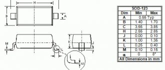
The diode bulb is always standard and is marked SOD123. It has a distinctive embossing or colored marking strip. Its color indicates the presence of negative polarity during the transition of electric current. The marking takes into account voltage, current limit values, power, etc. The appearance of the box does not matter and does not determine the method of operation of the electrodiode.
The following types of diodes are distinguished:
- The D9 family is marked with one or two colored rings in the anode area
- KD102 diodes in the anode area are indicated by a colored dot. Case transparent
- KD103 have a color body that complements the dot, with the exception of 2D103A, indicated by a white dot in the anode area
- The KD226, 243 families are marked with a cathode region ring. No other marks provided
- KD247 family - two colored rings in the cathode area
- KD410 diodes are indicated by a dot in the anode area
Color marking of zener diodes according to the JIS-C-7012 system (Japan), Color marking of diodes, zener diodes according to the JEDEC system (USA)
Color marking of diodes according to the European PRO ELECTRON system