Physical quantities used in marking the capacitance of ceramic capacitors
To determine the value of capacitance in the international system of units (SI), the Farad (F, F) is used. This is too large a value for a standard electrical circuit, so smaller units are used in marking household capacitors.
Table of capacitance units used for household ceramic capacitors
Unit name
| Designation options | Power relative to Farad | ||
| Microfarad | Microfarad | µF, µF, uF, mF | 10-6F |
| Nanofarad | Nanofarad | nF, nF | 10-9F |
| Picofarad | Picofarad | pF, pF, mmF, uuF | 10-12F |
The off-label unit millifarad is rarely used - 1 mF (10-3F).
Code marking of electrolytic capacitors for surface mounting
The following coding principles are used by such well-known companies as Hitachi and others. There are three main coding methods:
A. Marking with 2 or 3 characters
The code contains two or three characters (letters or numbers) indicating the operating voltage and rated capacity. Moreover, the letters indicate voltage and capacitance, and the number indicates the multiplier. In the case of a two-digit designation, the operating voltage code is not indicated.
Rice. 9
Table 14
| Code | Capacity | Voltage |
| A6 | 1,0 | 16/35 |
| A7 | 10 | 4 |
| AA7 | 10 | 10 |
| AE7 | 15 | 10 |
| AJ6 | 2,2 | 10 |
| AJ7 | 22 | 10 |
| AN6 | 3,3 | 10 |
| AN7 | 33 | 10 |
| AS6 | 4,7 | 10 |
| AW6 | 6,8 | 10 |
| CA7 | 10 | 16 |
| CE6 | 1,5 | 16 |
| CE7 | 15 | 16 |
| CJ6 | 2,2 | 16 |
| CN6 | 3,3 | 16 |
| CS6 | 4,7 | 16 |
| CW6 | 6,8 | 16 |
| DA6 | 1,0 | 20 |
| DA7 | 10 | 20 |
| DE6 | 1,5 | 20 |
| DJ6 | 2,2 | 20 |
| DN6 | 3,3 | 20 |
| DS6 | 4,7 | 20 |
| DW6 | 6,8 | 20 |
| E6 | 1,5 | 10/25 |
| EA6 | 1,0 | 25 |
| EE6 | 1,5 | 25 |
| EJ6 | 2,2 | 25 |
| EN6 | 3,3 | 25 |
| ES6 | 4,7 | 25 |
| EW5 | 0,68 | 25 |
| GA7 | 10 | 4 |
| GE7 | 15 | 4 |
| GJ7 | 22 | 4 |
| GN7 | 33 | 4 |
| GS6 | 4,7 | 4 |
| GS7 | 47 | 4 |
| GW6 | 6,8 | 4 |
| GW7 | 68 | 4 |
| J6 | 2,2 | 6,3/7/20 |
| JA7 | 10 | 6,3/7 |
| JE7 | 15 | 6,3/7 |
| JJ7 | 22 | 6,3/7 |
| JN6 | 3,3 | 6,3/7 |
| JN7 | 33 | 6,3/7 |
| JS6 | 4,7 | 6,3/7 |
| JS7 | 47 | 6,3/7 |
| JW6 | 6,8 | 6,3/7 |
| N5 | 0,33 | 35 |
| N6 | 3,3 | 4/16 |
| S5 | 0,47 | 25/35 |
| VA6 | 1,0 | 35 |
| VE6 | 1,5 | 35 |
| VJ6 | 2,2 | 35 |
| VN6 | 3,3 | 35 |
| VS5 | 0,47 | 35 |
| VW5 | 0,68 | 35 |
| W5 | 0,68 | 20/35 |
Rice. 10
B. 4-character marking
The code contains four characters (letters and numbers) indicating the capacity and operating voltage. The first letter indicates the operating voltage, the subsequent digits indicate the nominal capacitance in picofarads (pF), and the last digit indicates the number of zeros. There are 2 options for encoding the capacity: a) the first two digits indicate the nominal value in picofarads, the third - the number of zeros; b) the capacitance is indicated in microfarads, the m sign acts as a decimal point. Below are examples of marking capacitors with a capacity of 4.7 μF and an operating voltage of 10 V.
Rice. eleven
C. Two-line marking
If the size of the case allows, then the code is located in two lines: the capacitance rating is indicated on the top line, and the operating voltage is indicated on the second line. Capacitance can be indicated directly in microfarads (µF) or in picofarads (pf) indicating the number of zeros (see method B). For example, the first line is 15, the second line is 35V - means that the capacitor has a capacity of 15 uF and an operating voltage of 35 V.
Rice. 12
Numerical and numerical-alphabetic codes in capacitor markings
The designation is applied to the element body. The rated voltage in volts is usually indicated first; the numbers may be followed by the letters: V, V, VDC or VDCW. On small-area housings, the rated voltage value is applied in encoded form. If there is no indication of the permissible voltage in the circuit, this means that the capacitor can only be used in low-voltage circuits. There should be “+” and “-” signs on the case, indicating the polarity of connecting the element in the circuit. Failure to observe the specified polarity can lead to complete failure of the part.
Table for decoding letter codes of the rated voltage of ceramic capacitors
| Voltage, V | Code | Voltage, V | Code |
| 1 | I | 63 | K |
| 1,6 | R | 80 | L |
| 3,2 | A | 100 | N |
| 4 | C | 125 | P |
| 6,3 | B | 160 | Q |
| 10 | D | 200 | Z |
| 16 | E | 250 | W |
| 20 | F | 315 | X |
| 25 | G | 400 | Y |
| 32 | H | 450 | U |
| 40 | C | 500 | V |
| 50 | J |
The second position is the manufacturer’s sign or the temperature coefficient of the capacity (TKE), which may be absent. TKE is usually designated by a letter code.
Table of letter codes TKE for marking ceramic capacitors with non-standardized TKE
| Tolerance at -60°C…+80°C, +/-, % | Letter code | Tolerance at -60°C…+80°C, +/-, % | Letter code |
| 20 | Z | 70 | E |
| 30 | D | 90 | F |
The third position is the nominal capacity, which can be indicated in several ways.
Temperature coefficient of capacitance (TKE) Marking of capacitors with non-standardized TKE
table 2
| TKE Group | Tolerance at -6О…+85°С[%] | Letter code | Color* |
| H10 | ±10 | IN | orange+black |
| H20 | ±20 | Z | orange+red |
| H30 | ±30 | D | orange+green |
| H50 | ±50 | X | orange+blue |
| H70 | ±70 | E | orange+purple |
| H90 | ±90 | F | orange+white |
* Modern color coding, Colored stripes or dots. The second color can be represented by the color of the body.
Methods for marking capacitor capacity
On Soviet-made parts, most often having a fairly large surface area, the numerical values of the capacitance, its unit of measurement and the nominal voltage in volts were applied. For example, 23 pF, that is, 23 picofarads.
Deciphering the markings of modern ceramic capacitors of domestic and foreign production is a more complex undertaking. The following options are possible.
Three digits
If the marking contains three digits, then the first two indicate the capacity value, the last one is the zero multiplier. If the last digit is in the range 0-6, then the specified number of zeros is added to the number consisting of the first two digits. If the last digit is 8, then the number from the first two digits is multiplied by 0.01, if 9, then by 0.1. After determining the numerical value of the capacity, it is necessary to set the unit of measurement. The capacitance of small parts is usually measured in picofarads. After the numerical value there may be a letter indicating the unit of measurement: p – picofarad, µ – microfarad, n – nanofarad.
Example 353p = 35 x 103 pF.
Four digits
This option is similar to the one described above. Only the significant part contains three digits, and the fourth is the exponent for 10. The unit of measurement is usually picofarads.
Alphanumeric marking
With this method of designating a container, the letter indicates the place where the comma should be. The letter R is used to mark capacitance in microfarads. If there is a 0 in front of the letter R, then the unit of measurement is picofarad. For example, 0R4 = 4 pF, R47 = 0.45 µF.
The functions of a decimal point can be performed by a letter indicating a unit of measurement. For example, a capacitance of 0.43 μF on imported capacitors
designated as m43 or µ43. In the Russian version, the letters “p” are used as a decimal point – picofarads, “n” – nanofarads, “m” – microfarads.
In some cases, tolerances are applied to the capacitor housing for the nominal value of the capacitance. On large-area parts, they are indicated by numbers indicating the percentage of tolerance. For small capacitors, tolerances are usually marked in coded form.
Tolerance letter coding table
| Letter designation | Tolerance, % | Letter designation | Tolerance, % |
| B | +/- 0,1 | M | +/- 20 |
| C | +/- 0,25 | N | +/- 30 |
| D | +/- 0,5 | Q | -10…+30 |
| F | +/- 1 | T | -10…+50 |
| G | +/- 0,2 | Y | -10…+100 |
| J | +/- 0,5 | S | -20…+50 |
| K | +/- 10 | Z | -20…+80 |
Marking of imported capacitors
To date, the standards that have been adopted from the IEC apply not only to foreign types of equipment, but also to domestic ones. This system involves applying a code type marking to the product body, which consists of three direct numbers.
The two numbers that are located from the very beginning indicate the capacity of the item and in units such as picofarads. The number that is located third in order is the number of zeros. Let's look at this using the example of 555 - that's 5,500,000 picofarads. In the event that the capacity of the product is less than one picofarad, then the number zero is indicated from the very beginning.
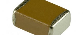
Marking of SMD capacitors
The dimensions of parts intended for surface mounting are very modest, so the designation contains a minimum of information, printed as concisely as possible. The voltage value is indicated by a letter code in accordance with the table presented above. Other marking elements:
- the first Latin letter characterizes the manufacturer of the component;
- the second Latin letter is the code of the significant part (mantissa) of the nominal capacity;
- the number indicates the power to which the encoded number must be raised to obtain the capacitance rating in picofarads.
For example, KT3 is a capacitor from the well-known manufacturer Kemet with a nominal capacity of 5.1x10³ pF = 5.1 nF.
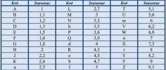
Mantissa coding table
| Letter | Mantissa | Letter | Mantissa | Letter | Mantissa |
| A | 1.0 | J | 2.2 | S | 4.7 |
| B | 1.1 | K | 2.4 | T | 5.1 |
| C | 1.2 | L | 2.7 | U | 5.6 |
| D | 1.3 | M | 3.0 | V | 6.2 |
| E | 1.5 | N | 3.3 | W | 6.8 |
| F | 1.6 | P | 3.6 | X | 7.5 |
| G | 1.8 | Q | 3.9 | Y | 8.2 |
| H | 2.0 | R | 4.3 | Z | 9.1 |
Tolerances
In accordance with the requirements of IEC Publications 62 and 115-2, the following tolerances and their coding are established for capacitors:
Table 1
| Tolerance [%] | Letter designation | Color |
| ±0,1* | V(W) | |
| ±0,25* | C(U) | orange |
| ±0,5* | D(D) | yellow |
| ±1,0* | F(P) | brown |
| ±2,0 | G(L) | red |
| ±5,0 | J(I) | green |
| ±10 | K(S) | white |
| ±20 | M(V) | black |
| ±30 | N(Ф) | |
| -10…+30 | Q(0) | |
| -10…+50 | T(E] | |
| -10…+100 | Y(Yu) | |
| -20…+50 | S(B) | violet |
| -20,..+80 | Z(A) | grey |
*-For capacitors with a capacity < 10 pF, the tolerance is indicated in picofarads.
Conversion of tolerance from % (δ) to farads (Δ):
Δ=(δхС/100%)[Ф]
Example:
The actual value of the capacitor marked 221J (0.22 nF ±5%) lies in the range: C = 0.22 nF ± Δ = (0.22 ±0.01) nF, where Δ = (0.22 x 10⁻⁹ [F] x 5) x 0.01 = 0.01 nF, or, respectively, from 0.21 to 0.23 nF.
Color coding of ceramic capacitors
Color coding is often used for capacitors with small surface area. Color stripes are applied from top to bottom or left to right. The nominal capacity is usually indicated by 3-5 colored stripes, the first two of which indicate a specific number. Black – 0, brown – 1, red – 2, orange – 3, yellow – 4, green – 5, blue – 6, purple – 7, gray – 8, white – 9.
The number, which is made up of the numbers encoded in the first two stripes, is multiplied by the multiplier encrypted in the third strip. The orange stripe means 103, yellow – 104, green – 105.
The marking may contain a fourth stripe, the color of which corresponds to the permissible deviations from the nominal capacity. White means 10% deviation in both directions is acceptable, and black means 20% in both directions. The fifth strip characterizes the voltage rating. Red – 250 V, yellow – 400 V.
Marking of capacitors with a linear dependence on temperature
Table 3
| GOST designation | International designation | TKE [ppm/°C]* | Letter code | Color** |
| P100 | P100 | 100 (+130…-49) | A | red+purple |
| P33 | 33 | N | grey | |
| MPO | NPO | 0(+30..-75) | WITH | black |
| M33 | N030 | -33(+30…-80] | N | brown |
| M75 | N080 | -75(+30…-80) | L | red |
| M150 | N150 | -150(+30…-105) | R | orange |
| M220 | N220 | -220(+30…-120) | R | yellow |
| M330 | N330 | -330(+60…-180) | S | green |
| M470 | N470 | -470(+60…-210) | T | blue |
| M750 | N750 | -750(+120…-330) | U | violet |
| M1500 | N1500 | -500(-250…-670) | V | orange+orange |
| M2200 | N2200 | -2200 | TO | yellow+orange |
* The actual spread for imported capacitors in the temperature range -55...+85°C is shown in brackets.
** Modern color coding according to EIA. Colored stripes or dots. The second color can be represented by the color of the body.
Features of capacitors
Capacitors are called two-terminal devices with a variable or specific capacitance value and low conductivity. A distinctive feature of the product is that it provides the accumulation of charge and energy of the electric field. The element itself is used as a passive electronic component. The design is not complicated - two electrodes in the form of plates, which are separated by a dielectric of small thickness. Elements with multilayer dielectrics and electrodes are increasingly being used.
There is a large selection of capacitors that are used in a wide variety of circuits. In order to correctly select the parameters of the electrical network, you should understand how ceramic capacitors are marked - this is their key importance. This is not entirely simple, since the parameters can differ significantly, depending on the manufacturing company, the exporting country, the type, size and parameters of the element itself.
Ceramic capacitors allow the accumulation of electrical charge. To measure capacitance, special units are used - farads (F). But it is worth considering that one unit of farad is a large quantity that is not used in radio engineering. In the case of capacitors, the microfarad is relevant - this is one farad divided by a million. Almost all elements have the designation μF. When familiarizing yourself with theoretical calculations, you sometimes come across millifarad - a farad divided by a thousand. Nanofarads and picofarads are used to designate small devices.
It is important to understand the notation in order to select the correct elements
Capacitor values vary, but what is this for in practice? A certain capacitor capacity is required if a significant amount of energy is to be released. That is, the element allows you to release in a fraction of seconds a considerable amount of energy, which will move in the direction that the person indicates.
The designation of capacitors in the diagram is carried out using two parallel segments, which symbolize the plates of the element with leads from their middles.
Note! The diagram next to it indicates the letter designation of the device - the letter C (from the Latin Capacitor - capacitor)
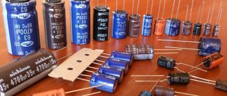
Fixed capacitors
Fixed capacitors are used in various circuits to separate the alternating and direct current components and smooth out the ripple of rectifier voltages. In combination with other circuit elements, capacitors form resonant circuits widely used in radio equipment. Fixed capacitors are classified according to their rated capacitance, accuracy class, rated operating voltage, purpose, dielectric material and design features.
The nominal values of capacitances of capacitors are established by GOST 2519 - 60. During the manufacture of capacitors, the actual value of the capacitance differs from the nominal value indicated in the marking. The permissible deviation of the capacitance from the nominal value is called tolerance. According to this principle, all capacitors are divided into five classes: 0, 1, II, III, IV, their tolerances are respectively ±2%; ±5%; ±10%; ±20% and from - 20 to + 50%.
Ceramic high voltage capacitor.
Depending on the purpose, there are loop, separating, blocking and filter capacitors. Based on the dielectric material, capacitors are divided into mica, ceramic, paper, metal-paper, paper-oil, film, glass-enamel, glass-ceramic, electrolytic, air, vacuum, gas-filled. Based on their design, capacitors are divided into tubular, disk, barrel, pot, crimped and sealed, flat and cylindrical, etc.
Regardless of the type, the capacitor is characterized by its operating voltage. The operating voltage is the voltage under which the capacitor plates can remain for a long time without breakdown of the dielectric separating them. Operating voltage is expressed in volts. Of great importance for the normal operation of the capacitor is the resistance of its insulation. With low insulation resistance, leaks occur that disrupt the normal operation of the circuit. Losses in a capacitor are characterized by the dielectric loss tangent, which expresses the ratio of the power of active losses to the reactive power of the capacitor.
In low-power capacitors, energy losses are mainly caused by dielectric conductivity and dielectric hysteresis, i.e., losses due to rotation of polar molecules in the direction of the field when voltage is applied to the plates. Losses in the plates and leads are small, so they are usually neglected. One of the most important characteristics of a capacitor is stability—the constant value of the capacitor’s capacitance during operation. The change in capacity can be either temporary or irreversible. The main factor influencing the stability of the capacitance of the capacitor is the effect of ambient temperature and heating of the capacitor due to the power dissipated on it. As the temperature rises, the geometric dimensions of the material increase, which entails a temporary (until the temperature returns to its original value) change in capacity.
What is a capacitor?
A device that stores electricity in the form of electrical charges is called a capacitor.
The amount of electricity or electric charge in physics is measured in coulombs (C). Electrical capacitance is calculated in farads (F).
A solitary conductor with an electrical capacity of 1 farad is a metal ball with a radius equal to 13 radii of the Sun. Therefore, a capacitor includes at least 2 conductors, which are separated by a dielectric. In simple device designs, paper is used.
The operation of a capacitor in a DC circuit is carried out when the power is turned on and off. Only during transient moments does the potential on the plates change.
The capacitor in the AC circuit recharges at a frequency equal to the frequency of the power source voltage. As a result of continuous charges and discharges, current flows through the element. A higher frequency means the device recharges faster.
The resistance of the circuit with a capacitor depends on the frequency of the current. At zero frequency of direct current, the resistance value tends to infinity. As the AC frequency increases, the resistance decreases.
Types of capacitors
A capacitor is two metal plates separated by a dielectric. They are distinguished by the type of dielectric, body material and plate production method. There are these types of capacitors:
- Paper. The plates in it are metal foil, and the dielectric is special paper. They are usually sealed into a metal case, as they are not durable. They behave normally both in low-frequency circuits and in high-frequency ones.
- Metal and paper. They differ in that metal coating is applied to the paper. They are more reliable, and have the same size as paper ones and have a larger capacity.
- Electrolytic. An oxide is applied to metal foil (tantalum or aluminum), which acts as a dielectric. The second layer of dielectric is the electrolyte. It can be dry or liquid. Usually electrolytic is called with a liquid electrolyte. Electrolytic capacitors are almost always polarized. And when connecting them, be sure to observe polarity. Otherwise they will simply fail. There are such subtypes: Although dry electrolyte capacitors are of the same type, they are usually called tantalum. It is with tantalum that dry electrolyte is usually used.
- Aluminum electrolytic capacitors. This is when aluminum trioxide is coated on aluminum foil. They have a large capacity with small sizes, but can only be used in low-frequency circuits. And another drawback is the high leakage current.
- It is correct to call tantalum capacitors made of tantalum foil, in which the dielectric is tantalum pentoxide. They are as compact as aluminum but have lower leakage current. And yet - they are more durable mechanically.
These are all types of capacitors that can now be found on sale and on boards. As you can see, there are a lot of them and they look completely different. Since some of the problems with equipment are related to their failure, it would be nice to understand their markings. This will take less time to find a replacement.
Designation of large capacitors
To correctly decipher the encoding, you need to prepare in advance. It is necessary to start with the basics - in what units the measurement is made. The capacitance of a device is measured in a unit called farad. It is designated by the letter F. The value 1F is large enough for ordinary household circuits, so small measurement values are used in marking. A commonly used measurement unit is microfarad. But millifarads can be used in calculations. This unit of measurement is outside the marking. The same popular units of measurement are nano and picofarad. A more accurate value can be obtained using a calculator.
- Digital marking of capacitors is applied directly to the surface. In some products, the designations may change, but basically you need to rely on the standard values that are given above in this article. And also do not forget that any meaning of numbers or letters can be found in professional literature in order to correctly decipher the meaning and avoid problems that may arise if the connection is incorrect in the electrical circuit. Therefore, do not forget about reference books.
- In some cases, the encoding is done in capital letters, and sometimes you can even notice abbreviations from the English farad. In addition, sometimes designations contain not only numbers, but also letters. As a rule, such values can be found on capacitors of small capacity.
There may be cases when tolerances are applied to the housing of capacitors, which are an acceptable deviation from the value of the capacitance of the product
This is very important because there are possible options when the collection of certain electrical circuits requires the presence of capacitors, the capacity of which is precisely known
The deviation can be shown as a percentage. If you do not find such a value in the percentage image on the surface, then you need to find the corresponding letter designation. As a rule, it is applied separately from the numerical value. A specific container size is associated with each individual letter. After such preparation, the design voltage can be calculated.
In the case where the surface area of the capacitor is large, the corresponding marking has a numerical value. Behind this designation there is usually a letter or combination of letters. Volts measure digital values that are considered the most acceptable when calculating voltage.
In the case where there are no markings on the surface of digital capacitors, they should only be used in low voltage electrical circuits. Determining polarity is of great importance. Misjudging the pros and cons can have serious consequences. This could be either an electrical short circuit or even an explosion. In the absence of any markings on the surface, connection in the circuit can be made to any terminals.
The meaning of the poles can be applied in the form of stripes of different colors or corresponding indentations in the form of a ring. In aluminum capacitors, such values correspond to the negative pole, and in tantalum capacitors, on the contrary, to the positive pole. If, however, there are images of minus and plus, then the color stripes can be ignored when connecting.
Experts recommend knowing the features and operating principle of a bipolar transistor.