How to determine the capacitance of an SMD capacitor?
A radio amateur who has encountered the type of SMD capacitor for the first time is perplexed as to how to understand all these “squares” and “barrels” if some do not have markings at all, and if there is one, you won’t understand what it means.
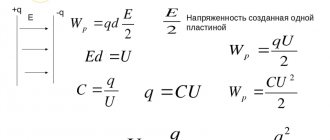
But you want to keep up with the times, which means you still have to figure out how to determine the identity of a board element and distinguish one component from another. As it turned out, there are still differences, and the markings, although not always and not on all capacitors, give an idea of the parameters. There are, of course, SMD components without identification marks, but first things first. First you need to understand what this element is and what its task is. This component works as follows. Each of the two plates located inside is supplied with opposite charges (their polarities differ), which tend to one another according to the laws of physics. But the charge cannot “penetrate” onto the opposite plate due to the fact that there is a dielectric spacer between them, and therefore, not finding a way out and not being able to “escape” from the nearby opposite pole, it accumulates in the capacitor until its capacity is filled.
Rules for decoding markings
First, let's look at the digital marking of capacitors. If the device is small, the EIA standard is used to indicate the capacity. If the code contains only two numbers followed by a letter, their value corresponds to the nominal capacity. The third digit in the code represents the zero multiplier. If it is in the range from 0 to 6, then the corresponding number of zeros must be added to the first two digits. Let's say the notation "463" is 46*103.
The units of measurement depend on the size of the device, and for small ones it is picofarads. In other cases, it is customary to use microfarads. When the digital designation is deciphered, you need to move on to the letters. When they are located within the first two characters, one of 2 methods is used:
- The letter “R” replaces the comma - the inscription 3R2 corresponds to a capacitance of 3.2 picofarads.
- The letter "p" is used as a decimal point - p60 corresponds to 0.6 picofarads. The letters "n" and "m" perform a similar task, but correspond to nano- and microfarads.
When can an online calculator help?
Mixed marking of capacitors can also be used, the interpretation of which is carried out in a similar way. However, the first letter in this case indicates the minimum operating temperature of the element. This is followed by the nominal capacity of the device and the maximum deviation indicators. Very small devices may be color coded. In such a situation, an online calculator can help you decipher the markings of capacitors. This will save a lot of time.
Types of capacitors
Capacitors vary in type, there are only three of them:
- Ceramic, film and similar non-polar ones are not marked, but their characteristics are easily determined using a multimeter. Capacitance range from 10 picofarads to 10 microfarads.
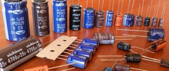
- Electrolytic - produced in the form of an aluminum barrel, marked, in appearance they resemble ordinary input ones, but are mounted on the surface.
- Tantalum – rectangular body, different sizes. Issue color: black, yellow, orange. Marked with a special code.
Electrolytic components
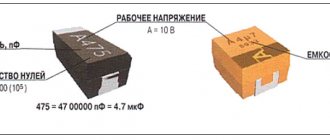
Such SMD components are usually marked with capacitance and operating voltage. For example, it could be 156v, which would mean that its characteristics are 15 microfarads and a voltage of 6 V.
Or it may turn out that the marking is completely different, for example D20475. A similar code defines a capacitor as 4.7 µF 20 V. Below is a list of letter designations along with their voltage equivalent:
- e – 2.5 V;
- G – 4 V;
- J – 6.3 V;
- A – 10 V;
- C – 16 V;
- D – 20 V;
- E – 25 V;
- V – 35 V;
- N – 50 V.
The bar, as well as the slice, shows the position of the “+” input.
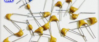
Ceramic components
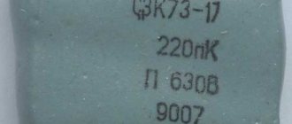
The marking of ceramic SMD capacitors has a wider number of symbols, although the code itself contains only 2-3 characters and a number. The first symbol, if present, indicates the manufacturer, the second indicates the rated voltage of the capacitor, and the number is the capacitance indicator in pF.
For example, the simplest marking T4 will mean that the capacitance of this ceramic capacitor is 5.1 × 10 to the 4th power pF.
The rated voltage designation table is presented below.
Marking table for ceramic storage devices
Marking of tantalum SMD capacitors
Such elements of standard sizes “a” and “b” are marked with a letter code according to the rated voltage. There are 8 such letters - these are G, J, A, C, D, E, V, T. Each letter corresponds to a voltage, respectively - 4, 6.3, 10, 16, 20, 25, 35, 50. It is followed by a capacitive code in pkF, consisting of three digits, the last of which will indicate the number of zeros. For example, the marking E105 indicates a capacitor of 1,000,000 pF = 10 μF, and its nominal value is 25 V.
Dimensions C, D, E are marked with a direct code, similar to the code for electrolytic capacitors.
The main difficulty in marking such capacitors is that at the moment, although there are generally accepted designation rules, some large and well-known companies are introducing their own system of designations and codes, which is radically different from the generally accepted one. This is done so that when repairing the printed circuit boards they produce, only original parts and SMD components are used.
How are large capacitors marked?
To correctly read the technical specifications of a device, some preparation is necessary. You need to start studying with units of measurement. To determine capacitance, a special unit is used - farad (F). The value of one farad for a standard circuit seems too large, so household capacitors are marked in smaller units. The most commonly used is mF = 1 µF (microfarad), which is 10 -6 farads.
In calculations, an off-label unit can be used - millifarad (1mF), which has a value of 10 -3 farads. In addition, designations can be in nanofarads (nF) equal to 10 -9 F and picofarads (pF) equal to 10 -12 F.
Large size markings are applied directly to the body. In some designs, the markings may differ, but in general, you need to be guided by the units of measurement mentioned above.
Designations are sometimes written in capital letters, for example, MF, which actually corresponds to mF - microfarads. The marking fd is also found - an abbreviation of the English word farad. Therefore mmfd will correspond to mmf or picofarad. In addition, there are designations that include a number and one letter. This marking looks like 400m and is used for small capacitors.
In some cases, it is possible to apply tolerances, which are an acceptable deviation from the rated capacitance of the capacitor. This information is of great importance when, when assembling certain types of electrical circuits, capacitors with precise capacitance values may be required. If we take the marking 6000uF + 50%/-70% as an example, then the maximum capacitance value will be 6000 + (6000 x 0.5) = 9000 uF, and the minimum 1800 uF = 6000 - (6000 x 0.7).
If there are no percentages, you need to find the letter. Usually it is located separately or after the numeric designation of the container. Each letter corresponds to a specific tolerance value. After this, you can begin to determine the rated voltage.
With large capacitor housing sizes, voltage markings are indicated by numbers followed by letters or letter combinations in the form V, VDC, WV or VDCW. The WV symbols correspond to the English phrase WorkingVoltage, which means operating voltage. Digital readings are considered to be the maximum permissible capacitor voltage, measured in volts.
If there is no voltage marking on the device body, such a capacitor should only be used in low-voltage circuits. In an AC circuit, use a device designed specifically for this purpose. Capacitors designed for direct current cannot be used without the ability to convert the rated voltage.
The next step is to identify the positive and negative symbols that indicate the presence of polarity. Determining the positive and negative is of great importance, since incorrect determination of the poles can lead to a short circuit and even explosion of the capacitor. In the absence of special markings, the device can be connected to any terminals, regardless of polarity.
The pole designation is sometimes applied in the form of a colored stripe or a ring-shaped indentation. This marking corresponds to the negative contact in electrolytic aluminum capacitors, which are shaped like a tin can. In tantalum capacitors with very small dimensions, these same symbols indicate positive contact
If there are plus and minus symbols, the color coding can be ignored
Designation in diagrams
In general, when repairing and re-soldering modern SMD printed circuit boards, it is most convenient when you still have a diagram at hand, looking at which it is much easier to understand what is installed, to find out the location of a certain part, because an SMD capacitor in appearance may not differ at all from the same transistor. The designations of these parts in the circuits remained the same as they were before the arrival of chips on the market, and therefore the capacity and other necessary characteristics can also be easily found by a radio amateur who has not encountered SMD components.
Four digit encoding
Marking of SMD capacitors
SMD drives with similar characteristics also differ in size. A number of standard sizes are shown in the table and figure below. It is especially important to take into account the dimensions of radio-electronic elements when designing printed circuit boards.
The marking of electrolytic SMD capacitors is practically no different from their output counterparts. A negative pad is indicated by a black mark on the flat side of the housing on the side of the corresponding pad. The permissible voltage in volts and capacitance in microfarads are also indicated.
Quite often there are cases that do not have any markings on them. Only a capacitance meter can help here.
Useful tips Connection diagrams Principles of operation of devices Main concepts Meters from Energomer Precautions Incandescent lamps Video instructions for the master Testing with a multimeter
How to determine the capacitance of an SMD capacitor without markings
SMD capacitors are available in various housings, ceramic, plastic and metal (aluminum).
Ceramic, film capacitors, etc. Non-polar ones are produced without marking. Capacitance varies from 1pF to 10uF.
Electrolytic capacitors are produced in the form of barrels in an aluminum case with markings, similar to lead capacitors, but for surface mounting.
Tantalum in rectangular cases, various sizes, black, yellow, orange. With code marking.
The markings for electrolytic and tantalum capacitors are similar to those for resistors, except that a "µ" symbol may be used.
Designation 105 - the first digit is 1, the second is 0, the multiplier is x10 5. We get 1,000,000 pF or 1 µF.
Designation 476 - the first digit is 4, the second is 7, the multiplier is x10 6. We get 47,000,000 pF or 47 µF.
The marking may contain the sign “µ” - 47 µ, indicating a capacitance of 47 µF
Marking 3 µ 3 - indicates a capacitance of 3.3 µF
The rated operating voltage is also indicated in the form of a numerical or letter designation.
The designation 35 will mean a nominal operating voltage of 35 volts.
There may also be a “v” icon next to the number, 10v - 10 Volts.
The voltage can be indicated by a letter of the Latin alphabet, before or after the numbers indicating the capacity.
e - 2.5v G - 4v J - 6.3v A - 10v C - 16v D - 20v E - 25v V - 35v H - 50v
On small-sized capacitors, due to the small area for marking, an alphabetic code designation consisting of three or two characters is used
If there are three characters, the first letter stands for Kemet
The second symbol indicates the capacity.
The third character is a number, indicating the multiplier.
Marking of imported capacitors
To designate imported, and in recent years, domestic radio elements, the recommendations of the IEC standard have been adopted, according to which a three-digit code marking is applied to the body of the radio element. The first two digits of the code indicate the capacitance in picofarads, the third digit is the number of zeros. For example, the numbers 476 indicate a capacitance of 47,000,000 pF (47 μF). If the capacitance is less than 1 pF, then the first digit is 0, and the symbol R is placed instead of a comma. For example, 0R5 – 0.5 pF.
For high-precision parts, a four-character encoding is used, where the first three characters determine the capacity, and the fourth - the number of zeros. The designation of tolerance, voltage and other characteristics is determined by the manufacturer.
Types of SMD capacitors
All storage devices used for surface mounting come in three main types: ceramic, electrolytic and tantalum.
Electrolytic
These surface mount components consist of:
- Aluminum cylindrical body, with a diameter from 4 to 10 mm and a height from 5.4 to 10.5 mm;
- Two sheets of thin foil, separated by paper soaked in electrolyte and rolled into a small roll;
- Two contacts (terminals) that are perpendicular to the centerline of the component. Since electrolytic SMD drives are polar, a negative potential is connected to one of the contacts, indicated by a special strip at the end of the case, and a positive potential is connected to the second.
- A mounting pad designed to secure a component to a work surface.
Various models of these components, rated from 1 to 1000-150 μF, are capable of operating at voltages from 4 to 1000 V.
Ceramic
The most commonly used surface mount ceramic multilayer storage device has the following structure:
- Ceramic body – a large number of thin layers of ceramic dielectric;
- Internal electrodes are thin nickel plates located between layers of ceramic dielectric;
- End contact electrodes – two terminals, each of which is connected to half of the internal electrodes.
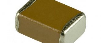
Unlike electrolytic ones, such components have a flattened rectangular shape and small dimensions (the length and width of the smallest radio components of this type are only 0.8 and 1.5-1.6 mm, respectively). However, despite their small size, such SMD components can operate at voltages from 25 to 700-1000V, while accumulating a charge ranging from 0.5-1.pF to 3-3.3 μF.
Tantalum
The main components of tantalum polar storage SMD devices are:
- Anode is a contact to which electric current is applied with a negative potential;
- Cathode – a contact located on the opposite side of the housing, powered by a positive potential;
- Dielectric - a layer of non-conducting material located between the anode and cathode;
- An electrolyte is a substance in a liquid or solid state of aggregation that conducts electric current. To prevent the capacitor from drying out, granular manganese oxide is most often used as an electrolyte.
- The dielectric is tantalum oxide, which coats the granular anode located in the housing.
Such small-sized storage devices are used with an operating voltage from 6 to 32-35 V. The amount of charge accumulated in this case ranges from 1 to 600-680 μF.
Digital marking
Digital markings are placed on small enclosures. Typically three or four digits are used, but five can also be found on specialized parts. Three and four include a denomination and a multiplier.
Three digits
The three numbers in the capacitor markings are the capacitance and the multiplier. The first two are the denomination, and the last is the power to which it must be raised. For example, the marking of the number 225 means 22 capacity, the third number is 5, this is a multiplier. Total 22*105 - in microfarads the result is 2.2 μF.
A multiplier of 9 is used when denoting capacitance less than 10 pF. For example, 209, the capacitance will be 2 pF.
Let's consider another example of marking capacitors with three numbers - 104. And again, the capacity is 10, the degree is 4. This means that the value of this capacitor is 10 * 104, which is 100,000 pF or 100 nF or 0.1 μF.
| Marking | Capacitance in microfarads (µF) | Capacitance in nanofarads (nF) | Capacitance in picofarads (pF) |
| 109 | 0,000001 | 0,001 | 1,0 |
| 159 | 0,0000015 | 0,0015 | 1,5 |
| 229 | 0,0000022 | 0,0022 | 2,2 |
| 339 | 0,0000033 | 0,0033 | 3,3 |
| 479 | 0,0000047 | 0,0047 | 4,7 |
| 689 | 0,0000068 | 0,0068 | 6,8 |
| 100 | 0,00001 | 0,01 | 10 |
| 150 | 0,000015 | 0,015 | 15 |
| 220 | 0,000022 | 0,022 | 22 |
| 330 | 0,000033 | 0,033 | 33 |
| 470 | 0,000047 | 0,047 | 47 |
| 680 | 0,000068 | 0,068 | 68 |
| 101 | 0,0001 | 0,1 | 100 |
| 151 | 0,00015 | 0,15 | 150 |
| 221 | 0,00022 | 0,22 | 220 |
| 331 | 0,00033 | 0,33 | 330 |
| 471 | 0,00047 | 0,47 | 470 |
| 681 | 0,00068 | 0,68 | 680 |
| 102 | 0,001 | 1 | 1000 |
| 152 | 0,0015 | 1,5 | 1500 |
| 222 | 0,0022 | 2,2 | 2200 |
| 332 | 0,0033 | 3,3 | 3300 |
| 472 | 0,0047 | 4,7 | 4700 |
| 682 | 0,0068 | 6,8 | 6800 |
| 103 | 0,01 | 10 | 10000 |
| 153 | 0,015 | 15 | 15000 |
| 223 | 0,022 | 22 | 22000 |
| 333 | 0,033 | 33 | 33000 |
| 473 | 0,047 | 47 | 47000 |
| 683 | 0,068 | 68 | 68000 |
| 104 | 0,1 | 100 | 100000 |
| 154 | 0,15 | 150 | 150000 |
| 224 | 0,22 | 220 | 220000 |
| 334 | 0,33 | 330 | 330000 |
| 474 | 0,47 | 470 | 470000 |
| 684 | 0,68 | 680 | 680000 |
| 105 | 1,0 | 1000 | 1000000 |
How to determine the rating and voltage
Many manufacturers do not indicate on their products such basic characteristics for any capacitor as operating voltage and rating (nominal capacity).
The rating of these electronic components is determined in the following ways:
- Using a measuring instrument such as a multimeter that has the function of measuring the nominal value. To measure the nominal value, the control probes of the device are connected to special connectors. Then the switch is set to the largest measurement limit (in most multimeters this is 200 µF). After this, the probes are applied to the contacts of the capacitor; after a few seconds, the value of the storage device’s rating is shown on the device’s display.
Important! Before measuring the capacitance, the SMD drive must be discharged - the charge remaining in the plates can damage the electronic circuits of the multimeter.
- Using a specialized RLC measuring device.
In order to find out the operating voltage of SMD device, use the following simple method:
- Using a multimeter, measure the voltage between the terminals of the component included in the circuit;
- The resulting value is multiplied by 1.5.
The operating voltage calculated in this way will be approximate; a more accurate value of this characteristic can be found from the marking code of the capacitor or its description.
Capacitor markings: decoding numbers and letters
Depending on the type of storage device, there are several methods for marking them.
Marking of ceramic devices
Devices of this type are marked with one or two Latin letters and a number. The first letter denotes the manufacturer of the component, the second – its nominal capacity. The number in the marking code indicates the capacitor rating in picofarads.
Example. The marking of the storage SMD component KG3 stands for a product manufactured and having a capacity of 1.8 × 10³ pF.
Marking of electrolytic SMD drives
Surface mount electrolytic storage devices are labeled in 4 main ways:
- In the form of one letter indicating the operating voltage and three numbers, two of which indicate the capacitance value of the capacitor, and the third - the degree of rating in picofarads.
- In the form of two letters indicating the operating voltage and capacitance, one number indicating the degree of rating in picofarads.
- Four-character is a designation consisting of one letter indicating the operating voltage, two numbers indicating the component's capacitance, and a final digit indicating the number of zeros after the capacitance value.
- Two-line - the upper part of the marking in the form of a number indicates the capacity of the component, the lower part indicates its operating voltage.
Marking of tantalum storage SMD devices
The marking of tantalum SMD drives consists of the following parts:
- A capital letter indicating the operating voltage of the component;
- A three-digit number, the first two digits of which indicate the storage capacity, and the last - the number of zeros after the capacity value.
Example. The marking of the G103 tantalum drive means that it has an operating voltage of 4 V and a capacity of 10,000 picofarads.
Why is labeling needed?
The task of labeling is to ensure that each specific element corresponds to certain performance characteristic values. Capacitor markings include the following:
- in fact, capacity is the main characteristic;
- maximum permissible voltage value;
- temperature coefficient of capacity;
- permissible deviation of capacity from the nominal value;
- polarity;
- year of issue.
The maximum voltage value is important because when its value is exceeded, irreversible changes occur in the element, up to its destruction. Temperature coefficient of capacitance (TKE) characterizes the change in capacitance with fluctuations in the temperature of the environment or the element body
This parameter is extremely important when the capacitor is used in frequency-setting circuits or as a filter element
The temperature coefficient of capacitance (TKE) characterizes the change in capacitance with fluctuations in the temperature of the environment or the body of the element. This parameter is extremely important when the capacitor is used in frequency-setting circuits or as a filter element.
Tolerance means the accuracy with which the rated capacitance of capacitors can vary.
Connection polarity is mainly characteristic of electrolytic capacitors. Failure to observe the switching polarity, at best, will lead to the fact that the actual capacity of the element will be greatly underestimated, and in reality the element will almost instantly fail due to mechanical destruction as a result of overheating or electrical breakdown.
The greatest difference in the principles of marking capacitors is observed in radioelements produced abroad and by enterprises in the post-Soviet space. All enterprises of the former USSR and those that continue to operate now code their products according to a single standard with minor differences.
SDM capacitors without markings
When working with SMD capacitors, many radio amateurs encounter certain difficulties, since on the first try it is very difficult to understand the symbols on them. There are also capacitor products that are not marked at all.
As a result, the question of how to identify an smd capacitor without markings seems very important for all fans of installing radio equipment. But before learning to identify unmarked domestic and imported containers, it is advisable to familiarize yourself with their varieties.
Marking of SMD components
Sometimes it seems to me that the labeling of modern electronic components has turned into a whole science, similar to history or archeology, since in order to figure out which component is installed on the board, sometimes you have to conduct a whole analysis of the elements surrounding it. In this regard, the Soviet output components, on which the denomination and model were written in text, were simply a dream for an amateur, since there was no need to rummage through piles of reference books to figure out what these parts were.
The reason lies in the automation of the assembly process. SMD components are installed by robots, in which special reels are installed (similar to the reels with magnetic tapes) in which chip components are located. The robot doesn’t care what’s in the bag or whether the parts are marked. Humans need labeling.
Types of SMD capacitors
Various names of SMD capacitors are divided into three classes according to their functional purpose:
- Ceramic or film non-polar products with ratings from 10 picofarads to 10 microfarads, which are usually not marked;
- Electrolytic capacitors shaped like an aluminum barrel designed for surface mounting;
- Tantalum capacitor parts having a rectangular body of various sizes. Available with color (black, yellow or orange) markings, supplemented by a special code.
All listed products must have a designation made in the form of markings that comply with the standard. But often it is missing for one reason or another (it is erased, washed off or was not applied during handicraft production). In this case, it is necessary to take some steps to fully identify them.
Types and markings
Capacitors are classified into groups, depending on the type of dielectric used between the plates, as well as by purpose.
Dielectric classification:
- vacuum;
- gas;
- electrolytic and oxide semiconductor;
- ceramic.
According to their purpose, devices are divided into:
- with a constant capacity for building various circuits or as a filter;
- with a variable to change the capacitance, for example, in the oscillatory circuit of a radio receiver or other frequency equipment;
- tuning devices for correcting the capacitance of the main capacitor during assembly and calibration of equipment and instruments.
The type is usually not indicated on the body, since there is simply not enough space for this. In older models this was indicated by letter markings. The first letter “K” meant a capacitor, and the second meant a dielectric material. For example, KK is a ceramic capacitor.
With the development of technology, this method lost its ability to display the entire range of models, so a new digital marking system was developed, in which the number indicated the membership group. To decipher the groups, they used tables that were also outdated.
The marking of modern models displays only the capacity, deviation tolerances and maximum permissible voltage, and sometimes the manufacturer or brand. The type is indicated in the accompanying documentation and on the packaging. At the same time, the meaning of digital classification into groups was lost.
You can also tell which capacitor is by its appearance. Electrolytic ones have a cylindrical shape, their plates and dielectric layer are made in the form of a tape and wound into a roll, so the shape is appropriate.
Ceramic ones have a flat shape in the form of a tablet or parallelepiped. Models with variable capacity are equipped with a rotary handle or have a control contact - a third leg. The subscripts provide a slot for adjustment with a screwdriver.
How to determine the rating and voltage
Each miniature capacitor is characterized by two main parameters: the nominal capacity and the maximum voltage at which it can still operate. Let us consider the procedure for identifying each of these indicators in more detail.
Nominal value
To determine the first of the parameters, you can use the following methods:
- Try to measure their nominal capacity using a device (multimeter) that has the appropriate function;
- Use a special RLC meter for these purposes.
Note! Both of these methods involve removing the capacitor from the board or soldering at least one pad.
The procedure for measuring SMD capacitors with both devices can be found in the instructions for their use.
Operating voltage
In order to demonstrate the situation with the maximum operating voltage of a given element, there is only one reliable way. It consists of trying to measure the voltage between the contacts where an unknown capacitor is sealed (with the equipment turned on, of course).
After determining this indicator, we can assume that the capacitor itself is designed for a voltage approximately one and a half times higher than the value obtained after the measurement.
Planar electrolytic capacitors
Designation of capacitors in circuits
However, Soviet capacitors, distinguished by a small but varied marking, are still in wide circulation. Everything was involved in Soviet markings - numbers, letters and colors. Moreover, both numbers and letters, as well as colors, numbers and letters, were applied to the housings of the elements. The numbers indicate the value, the letters indicate the units of measurement.
Also, previously only color marking was used - a solid color with a colored dot. The parameters can only be determined using the reference book.
The types of markings discussed above are gradually going out of use, but they are always remembered by specialists who repair Soviet equipment in which radioelements have the “old” designation.
In addition to capacity, drives are characterized by a number of basic parameters, which are discussed below.
Expert opinion
It-Technology, Electrical power and electronics specialist
Ask questions to the “Specialist for modernization of energy generation systems”
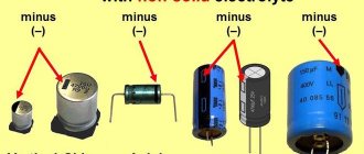
Examples: Well, finally, I’ll give you a picture that will help us decide on the polarity of connecting electrolytic and tantalum SMD capacitors. Ask, I'm in touch!
Electrolytic components
It is known that the marking of an electrolytic capacitor has its own characteristics, which are manifested in the indication of another additional parameter - the polarity of the inclusion. If this designation is missing, the only way to restore the lost information is to remove it from the circuit and determine the voltage polarity in this area using a multimeter.
Additional Information. Before soldering the identified product from the board, you should mark its legs in some way that allows you to fix their location in the circuit.
In conclusion, we note that for any type of capacitor product, determining the rating or operating voltage will require the ability to handle special measuring equipment.
How to find out where the polarity of a capacitor is
Most elements have a more or less uniform polarity marking system. The capacitor polarity designation has several types that are easy to remember:
- Appearance (body shape, length and thickness of legs);
- Marking (applying appropriate symbols at the terminals or on the body);
- Designations on electronic circuits.
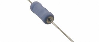
By appearance
How to determine the polarity of a capacitor by appearance? This is easiest to do for devices with a cylindrical body, in which the leads are located at opposite ends (axial type of body). Even if the marking is completely erased, the terminal that is connected directly to the metal case has a minus sign.
The terminal installed on the housing through an insulator (in this place there is usually a thickening or change in the shape of the housing) corresponds to positive polarity, that is, “plus”.
Axial body shape
Newer, non-welded types of aluminum designs with legs located in close proximity to each other (radial body) have a longer positive lead.
Sometimes in old equipment you can find electrolytic capacitors with one terminal, which are attached to the body of the structure with a nut. Here the nut is “minus”, the terminal is “plus”.
Nut fastening
Even more rarely, you come across elements with a nut fastening, but with two terminals. The principle of marking is in many ways similar to the previous case, but here we are dealing with a dual capacitor, in which the common “minus” is located on the body, and the “plus” is located on the terminals (each terminal corresponds to a separate capacitance).
By labeling
Manufacturers also apply markings on the body of the elements. There may be several options here:
- The minus sign is on the side surface of the cylinder from the negative terminal side;
- The plus sign is directly at the positive leg of the element;
- A wide dark stripe at the end opposite the negative terminal (usually on solid-state electrolytic capacitors.
Note! For SMD components, the designation is the opposite - a wide light or dark stripe near the positive pad. Marking of solid-state and SMD components
Marking of solid-state and SMD components
According to the scheme
On electrical diagrams, capacitors are indicated in the form of two parallel lines, which symbolize the plates. A “+” symbol is placed near the positive terminal, or this terminal is indicated by a thicker line, or in the form of a narrow rectangle.
Some electronics manufacturers draw the negative terminal in the form of an arc segment on the diagrams.
Designation on circuit diagrams
On printed circuit boards, an electrolytic capacitor has the following polarity designations:
- As in electrical circuit diagrams;
- In the form of a circle, in which a narrow segment is painted over at the place where the negative terminal is soldered.
SDM capacitors without markings
Many novice radio amateurs are faced with the problem of determining the characteristics of storage devices such as SMD capacitors. Small in size and used in surface mount technologies, these components on many printed circuit boards are labeled differently than their larger through-hole mount counterparts. This article will discuss the main types of radio component data, their designation and its interpretation.
Types of SMD capacitors
All storage devices used for surface mounting come in three main types: ceramic, electrolytic and tantalum.
Electrolytic
These surface mount components consist of:
- Aluminum cylindrical body, with a diameter from 4 to 10 mm and a height from 5.4 to 10.5 mm;
- Two sheets of thin foil, separated by paper soaked in electrolyte and rolled into a small roll;
- Two contacts (terminals) that are perpendicular to the centerline of the component. Since electrolytic SMD drives are polar, a negative potential is connected to one of the contacts, indicated by a special strip at the end of the case, and a positive potential is connected to the second.
- A mounting pad designed to secure a component to a work surface.
Various models of these components, rated from 1 to 1000-150 μF, are capable of operating at voltages from 4 to 1000 V.
Ceramic
The most commonly used surface mount ceramic multilayer storage device has the following structure:
- Ceramic body – a large number of thin layers of ceramic dielectric;
- Internal electrodes are thin nickel plates located between layers of ceramic dielectric;
- End contact electrodes – two terminals, each of which is connected to half of the internal electrodes.
Unlike electrolytic ones, such components have a flattened rectangular shape and small dimensions (the length and width of the smallest radio components of this type are only 0.8 and 1.5-1.6 mm, respectively). However, despite their small size, such SMD components can operate at voltages from 25 to 700-1000V, while accumulating a charge ranging from 0.5-1.pF to 3-3.3 μF.
Tantalum
The main components of tantalum polar storage SMD devices are:
- Anode is a contact to which electric current is applied with a negative potential;
- Cathode – a contact located on the opposite side of the housing, powered by a positive potential;
- Dielectric - a layer of non-conducting material located between the anode and cathode;
- An electrolyte is a substance in a liquid or solid state of aggregation that conducts electric current. To prevent the capacitor from drying out, granular manganese oxide is most often used as an electrolyte.
- The dielectric is tantalum oxide, which coats the granular anode located in the housing.
Such small-sized storage devices are used with an operating voltage from 6 to 32-35 V. The amount of charge accumulated in this case ranges from 1 to 600-680 μF.
Marking and designation of capacitors, ceramic tantalum and others
SMD ceramic capacitors (chip) are multilayer ceramic capacitors of constant capacity for surface mounting, the range of accumulated charge is from 0.5 pF to 3.3 μF at a voltage from 25 V to 1000 V. The permissible deviation of the capacity is ±5% , ±10% , ±20% .
Structurally, capacitors for surface mounting, depending on overall dimensions, are divided into several size groups : 0603 (1.6x0.8 mm), 0805 (2.0x1.2 mm), 1206 (3.2x1.6 mm), 1210 (3. 2x2.5 mm), 1812 (4.5x3.2 mm), 2225 (5.6x6.4 mm).
The presented ceramic SMD capacitors use several types of inorganic dielectric :
- NPO dielectric , characterized by high quality factor and linear temperature dependence
- dielectrics of types X7R and Y5V - have higher loss levels and semi-stable temperature dependence
Installation of capacitors on a printed circuit board is carried out by reflowing solder using infrared heating or a jet of hot gas; automated soldering methods in ovens are allowed. to make a stencil before applying solder paste to prevent damage to the PCB.
The elevated operating temperature of the environment is no more than +125°C , the reduced operating temperature is not lower than -55°C . The maximum tangent tanδ is not higher than 0.035.
are used as filtering, separating and blocking devices in various electronic equipment and technology (oscilloscopes, frequency dividers, telephones, modems, medical equipment, etc.).
Detailed characteristics, identification of markings, overall and installation dimensions, design of ceramic multilayer SMD capacitors are given below. Our company guarantees the quality and performance of capacitors for 2 years from the date of purchase; quality certificates are provided.
The final price for ceramic SMD capacitors depends on the quantity, delivery time and form of payment.
Expert opinion
It-Technology, Electrical power and electronics specialist
Ask questions to the “Specialist for modernization of energy generation systems”
Units of Measurement A negative pad is indicated by a black mark on the flat side of the housing on the side of the corresponding pad. Ask, I'm in touch!
How to determine the rating and voltage
Many manufacturers do not indicate on their products such basic characteristics for any capacitor as operating voltage and rating (nominal capacity).
The rating of these electronic components is determined in the following ways:
- Using a measuring instrument such as a multimeter that has the function of measuring the nominal value. To measure the nominal value, the control probes of the device are connected to special connectors. Then the switch is set to the largest measurement limit (in most multimeters this is 200 µF). After this, the probes are applied to the contacts of the capacitor; after a few seconds, the value of the storage device’s rating is shown on the device’s display.
How to test a ceramic capacitor
Non-polar capacitors (ceramic, paper, etc.) are checked with a multimeter in a slightly different way:
- We set up the device to measure resistance.
- We set the maximum measurement limit.
- We touch the measuring leads to the contacts without touching them.
If, as a result of these actions, the resistance value on the device screen is greater than 2 MΩ. – the capacitor is OK. If the resistance reading obtained is less than 2 Mohms. – the element is faulty (the capacitor is broken or shorted). It needs to be replaced with a good one.
Remember that when measuring at maximum resistance modes, it is imperative to avoid touching conductive parts. This is due to the fact that the resistance of the human body is much less than the resistance of the capacitor. This resistance has a great influence on the accuracy of the measurement. The tester does not show the correct parameters.
Capacitor markings: decoding numbers and letters
Depending on the type of storage device, there are several methods for marking them.
Marking of ceramic devices
Devices of this type are marked with one or two Latin letters and a number. The first letter denotes the manufacturer of the component, the second – its nominal capacity. The number in the marking code indicates the capacitor rating in picofarads.
Example. The marking of the storage SMD component KG3 stands for a product manufactured and having a capacity of 1.8 × 10³ pF.
Marking of electrolytic SMD drives
Surface mount electrolytic storage devices are labeled in 4 main ways:
- In the form of one letter indicating the operating voltage and three numbers, two of which indicate the capacitance value of the capacitor, and the third - the degree of rating in picofarads.
- In the form of two letters indicating the operating voltage and capacitance, one number indicating the degree of rating in picofarads.
- Four-character is a designation consisting of one letter indicating the operating voltage, two numbers indicating the component's capacitance, and a final digit indicating the number of zeros after the capacitance value.
- Two-line - the upper part of the marking in the form of a number indicates the capacity of the component, the lower part indicates its operating voltage.
Marking of tantalum storage SMD devices
The marking of tantalum SMD drives consists of the following parts:
- A capital letter indicating the operating voltage of the component;
- A three-digit number, the first two digits of which indicate the storage capacity, and the last - the number of zeros after the capacity value.
Example. The marking of the G103 tantalum drive means that it has an operating voltage of 4 V and a capacity of 10,000 picofarads.
Important! When connecting tantalum and electrolytic storage devices, polarity must be observed. To do this, a special strip is applied to their cases, which is black and indicates a positive (for tantalum drives) or negative (for electrolytic devices) terminal. Incorrect connection and ignoring these labels will cause the drive to fail.
How are large capacitors marked?
Large storage SMD devices are marked according to the same principles as their smaller counterparts. With large case sizes, such components are often marked with the full value of their capacitance and operating voltage.
On a note. For the search query “smd capacitors without marking, how to identify”, in addition to websites, on the first page of the search results, various forums of radio amateurs and specialists involved in the repair of computer and household appliances contain useful information on this topic. Designation in diagrams.
On electrical diagrams, SMD storage devices have the same designation as their analogues used for through installation.
Thus, the ability to read and decipher marking codes allows you to correctly determine the characteristics of these drives. Such skills are very important when replacing failed drives and soldering complex circuits that are sensitive to changes in the current-voltage characteristics of electric current.
Minus symbol
The principle of polarity marking of imported products differs from traditional standards of the domestic industry and consists of an algorithm. The location of the negative contact is indicated by both special symbols and the color of the housing.
For example, on a black cylindrical body, the negative terminal side, sometimes called the cathode, has a light gray stripe applied along the entire height of the cylinder. A dashed line, or elongated ellipses, or a minus sign is printed on the strip, as well as 1 or 2 angle brackets, pointed at the cathode at an acute angle. The model range with other denominations is distinguished by a blue body and a pale blue stripe on the side of the negative contact.
Other colors are also used for marking, following the general principle: dark body and light stripe. Such markings are never completely erased and therefore you can always confidently determine the polarity of the “electrolyte,” as electrolytic capacitors are called for brevity in radio engineering jargon.
The body of SMD containers, manufactured in the form of a metal aluminum cylinder, remains unpainted and has a natural silver color, and the segment of the round upper end is painted with an intense black, red or blue color and corresponds to the position of the negative terminal. After mounting the element on the surface of the printed circuit board, the partially painted end of the housing, indicating the polarity, is clearly visible on the diagram, since it has a greater height compared to flat elements.
The polarity designation of a cylindrical SMD device corresponding to the marking is applied to the surface of the board: this is a circle with a segment shaded with white lines where the negative contact is located. However, it should be noted that some manufacturers prefer to mark the positive contact of the device in white.