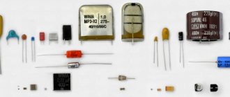
In the manufacture of almost any radio crafts, resistors are used. I think there is no need to explain what it is and how it works, and the purpose of this article is somewhat different. I would like to focus on the standard sizes of SMD resistors, and in addition to indicating the dimensions, mention their designation, that is, markings and power dissipation. All these are important parameters, because how do you know what to order for a project, and besides, be sure that the transistor will withstand the current passing through it. Well, this is where the introduction ends and the substance of the material begins.
Let's immediately turn to the table; it seems to me that this is the most valuable material.
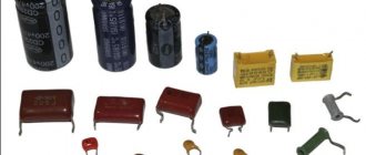
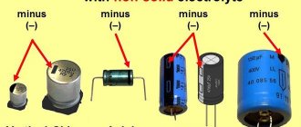
Electrolytic
These surface mount components consist of:
- Aluminum cylindrical body, with a diameter from 4 to 10 mm and a height from 5.4 to 10.5 mm;
- Two sheets of thin foil, separated by paper soaked in electrolyte and rolled into a small roll;
- Two contacts (terminals) that are perpendicular to the centerline of the component. Since electrolytic SMD drives are polar, a negative potential is connected to one of the contacts, indicated by a special strip at the end of the case, and a positive potential is connected to the second.
- A mounting pad designed to secure a component to a work surface.
Various models of these components, rated from 1 to 1000-150 μF, are capable of operating at voltages from 4 to 1000 V.
Passive components: Electrolytic capacitors
| TYPE: | Type Explanation: | ||||
| S.E. | Aluminum Capacitor Aluminum capacitor (polar component) | ||||
| Case diameter | Case height | Tape width | Component pitch in the ribbon | Qty per standard package (180 mm/7 inches) plastic tape | Qty per standard pack (330 mm/13 inches) plastic tape |
| 3 mm | 5.5 mm | 12 mm | 8 mm | 100 | 2000 |
| 4 mm | 5.5 mm | 12 mm | 8 mm | 100 | 2000 |
| 5 mm | 5.5 mm | 12 mm | 12 mm | 100 | 1000 |
| 6.3 mm | 5.5 mm | 16 mm | 12 mm | 100 | 1000 |
| 8 mm | 6 mm | 16 mm | 12 mm | 100 | 1000 |
| 8 mm | 10 mm | 24 mm | 16 mm | 100 | 500 |
| 10 mm | 10 mm | 24 mm | 16 mm | 100 | 300 — 500 |
| 10 mm | 14 - 22 mm | 32 mm | 20 mm | — | 250 — 300 |
| 12.5 mm | 14 mm | 32 mm | 24 mm | — | 200 — 250 |
| 12.5 mm | 17 mm | 32 mm | 24 mm | — | 150 — 200 |
| 12.5 mm | 22 mm | 32 mm | 24 mm | — | 125 — 150 |
| 16 mm | 17 mm | 44 mm | 28 mm | — | 125 — 150 |
| 16 mm | 22 mm | 44 mm | 28 mm | — | 75 — 100 |
| 18 mm | 17 mm | 44 mm | 32 mm | — | 125 — 150 |
| 18 mm | 22 mm | 44 mm | 32 mm | — | 75 — 100 |
| 20 mm | 17 mm | 44 mm | 36 mm | — | 50 |
Resistors
Passive Components: Resistors
| TYPE: | Type Explanation: | |||||
| S.R. | Resistor Chip Resistor chip | |||||
| Size (inches) | Size(mm) | Component Thickness | Tape width | Component pitch in the ribbon | Quantity in standard packaging (180 mm/7 inches) paper tape | Qty per standard package (180 mm/7 inches) plastic tape |
| 01005 | 0402 | 0.12 mm ± 0.02 | 8 mm | 2 mm | 20000 | — |
| 0201 | 0603 | 0.23 mm ± 0.03 | 8 mm | 2 mm | 15000 | — |
| 0402 | 1005 | 0.35 mm ± 0.05 | 8 mm | 2 mm | 10000 | — |
| 0603 | 1608 | 0.45 mm ± 0.1 | 8 mm | 4 mm | 5000 | — |
| 0805 | 2012 | 0.55 mm ± 0.1 | 8 mm | 4 mm | 5000 | — |
| 1206 | 3216 | 0.55 mm ± 0.15 | 8 mm | 4 mm | 5000 | — |
| 1210 | 3225 | 0.55 mm ± 0.15 | 8 mm | 4 mm | 5000 | 4000 |
| 2010 | 5025 | 0.55 mm ± 0.15 | 8/12 mm | 4/8 mm | — | 4000 |
| 2512 | 6332 | 0.55 mm ± 0.15 | 12 mm | 4/8 mm | — | 4000/2000 |
Passive Components: Resistors
| TYPE: | Type Explanation: | ||||
| SRM | Melf Resistor Melf resistor (round) | ||||
| Size (inches) | Name | Component size | Tape width | Component pitch in the ribbon | Qty per standard package (180 mm/7 inches) plastic tape |
| 0604 | — | 1.6 mm X 1.0 mm | 8 mm | 4 mm | 3000 |
| 0805 | Micro | 2.2 mm X 1.1 mm | 8 mm | 4 mm | 3000 |
| 1206 | Mini | 3.2 mm X 1.6 mm | 8 mm | 4 mm | 3000 |
| 1406 | Mini | 3.5 mm X 1.4 mm | 8 mm | 4 mm | 3000 |
| 2308 | Melf | 5.9 mm X 2.2 mm | 12 mm | 4 mm | 1500 |
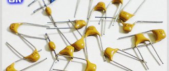
Ceramic components
In ceramic elements, porcelain or similar inorganic materials are used as a dielectric. The main advantage of such products is their resistance to high temperatures and the ability to produce products of extremely small sizes.
Important! SMD ceramic capacitors are also installed by soldering onto a printed circuit board.
Visually, such an element, as a rule, resembles a small brick to which contact pads are soldered at the ends.
Ceramic SMD capacitors
Unlike radio components of standard sizes, SMD elements of small size are first glued to the board, and only then the leads are soldered. In production, ceramic products of this type are installed by special automatic machines.
Marking of ceramic SMD capacitors
Small ceramic SMD capacitors are marked with an alphanumeric code consisting of 3 characters. The first indicates the minimum operating temperature, for example:
- Z - from 10 °C;
- Y - from −30 °С;
- X - from 55 °C.
Marking of SMD capacitors
The second symbol indicates the upper limit of heating of the radio component:
- 2 - up to 45 °C;
- 4 - up to 65 °C;
- 5 - up to 85 °C;
- 6 - up to 105 °C;
- 7 - up to 125 °C;
- 8 - up to 150 °C;
- 9 - up to 200 °C.
The third character indicates the accuracy of the electronic component:
- A - up to ± 1.0%;
- B - up to ± 1.5%;
- C - up to ± 2.2%;
- D - up to ± 3.3%;
- E - up to ± 4.7%;
- F - up to ± 7.5%;
- P - up to ± 10%;
- R - up to ± 15%;
- S - up to ± 22%;
- T - up to ± 33%;
- U - up to ± 56%;
- V - up to ± 82%.
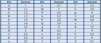
The capacity of small ceramic SMD capacitors is indicated in picofarads. To save the area of a small radio element, the main mantissa number is encoded in a letter of the Latin alphabet. The table below provides a complete list of such designations.
Table with encoded characters
After the number, the multiplier is indicated, for example, the designation on a ceramic capacitor X3 means that the capacitor has a capacity of 7.5 * 10 ^ 3 Pf.
Note! The code indicating the capacity of a ceramic SMD capacitor may be preceded by a Latin letter, which indicates the brand of the manufacturer of the electronic component.
If the area of this type of ceramic capacitor is large enough, then the dielectric type can be displayed on it. For this purpose the following are used:
- NP0. The dielectric constant of such an element is at an extremely low level. The main advantage of components of this type is their good resistance to sudden temperature changes. The disadvantage of elements that use this type of dielectric is their high price;
- X7R. Average quality dielectric. Products that use this type of insulator do not have excellent breakdown resistance characteristics, but in the average temperature range they are able to work significantly longer than many more expensive elements;
- Z5U. A dielectric with high electrical permeability values, but the downside of this indicator is that the capacitance error is too large;
- Y5V. The insulating material has approximately the same characteristics as Z5U. In terms of cost, this dielectric is the cheapest, so electrical components made on its basis are sold at the lowest prices.
You may be interested in this. What is the unit of measurement for current?
Burnt SMD capacitor
Considering all of the above, you can be sure that if the SMD capacitor has not burned or changed the color of the surface for other reasons, then you can always determine its value by the markings on its body.
Passive Components: Capacitors
| TYPE: | Type Explanation: | |||||
| S.C. | Ceramic Chip Capacitor Ceramic chip capacitor | |||||
| Size (inches) | Size(mm) | Component Thickness | Tape width | Component pitch in the ribbon | Quantity in standard packaging (180 mm/7 inches) paper tape | Qty per standard package (180 mm/7 inches) plastic tape |
| 01005 | 0402 | 0.2 mm ± 0.03 | 8 mm | 2 mm | 20000 | — |
| 0201 | 0603 | 0.3 mm ± 0.03 | 8 mm | 2 mm | 15000 | — |
| 0402 | 1005 | 0.5 mm ± 0.1 | 8 mm | 2 mm | 10000 | — |
| 0603 | 1608 | 0.8 mm ± 0.1 | 8 mm | 4 mm | 4000 | — |
| 0805 | 2012 | 0.6 – 1.25 mm | 8 mm | 4 mm | 4000 | 3000 |
| 1206 | 3216 | 0.6 – 1.25 mm | 8 mm | 4 mm | 4000 | 3000 |
| 1210 | 3225 | 1.25 mm – 1.5 mm | 8 mm | 4 mm | — | 3000 |
| 1812 | 4532 | 2 mm (Max.) | 12 mm | 8 mm | — | 1000 |
| 2225 | 5664 | 2 mm (Max.) | 12 mm | 8 mm | — | 1000 |
Yageo Ceramic Chip Capacitors
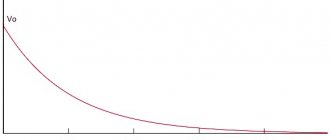
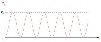
It is difficult to find a modern electronic device without ceramic chip capacitors. They are used in circuits where good frequency response, small size, low losses, low leakage currents and long-term stability are required. The development of technology has made it possible to implement ceramic chip capacitors with a capacity of 100 μF or more, which allows them to replace electrolytic or tantalum capacitors, reduce the size of components, improve the stability of parameters and increase the service life of the device. The type of dielectric of a chip capacitor characterizes the accuracy and stability of its parameters. The most common types of dielectrics are NP0, X7R, X5R, Y5V. Dependences illustrating the change in capacitance as a function of temperature for three types of dielectric NP0, X7R and Y5V are shown in Figure 1.
Rice. 1. Dependence of the capacitance of chip capacitors on temperature for different dielectrics
From the graphs in Figure 1 it is clearly seen that chip capacitors with an NP0 dielectric have the best stability of parameters (the capacitance practically does not change in the temperature range from -55 to 125°C). The maximum changes in capacitance are typical for capacitors with a Y5V dielectric. In the temperature range from -40 to 85°C, the change in capacity reaches 80%. Such capacitors may have high capacitance values, but low stability of parameters. The X7R dielectric provides intermediate stability of capacitance between NP0 and X7R (the change in capacitance in the temperature range from -55 to 125°C is about 10%). All capacitors with the most popular types of dielectrics considered are widely used. They differ in price and overall dimensions for the same capacitance values and rated voltage. The main parameters of the most common series of Yageo chip capacitors are summarized in Table 1.
Table 1. Main parameters of YAGEO chip capacitors
| Name | Properties | Capacity range | Voltage range, V | Dimensions* |
| NP0 | General use | 0.22 pF…33 nF | 16…25 | 0201, 0402, 0603, 0805, 1206, 1210 |
| General use | 0.22 pF…390 pF | 50 | 0201, 0402, 0603, 0805, 1206, 1210, 1812 | |
| Medium voltage | 10 pF…22 nF | 100…630 | 0603, 0805, 1206, 1210, 1808, 1812 | |
| High voltage | 10 pF…2.7 nF | 1000, 2000, 3000, 4000 | 1206, 1210, 1808, 1812 | |
| Microwave | 0.47 pF…120 pF | 50 | 0603, 0805, 1206 | |
| High frequency | 0.22 pF…10 pF | 50 | 0402, 0603 | |
| X7R | General purpose and high capacity | 100 pF…22 µF | 6,3…50 | 0201, 0402, 0603, 0805, 1206, 1210, 1812 |
| Medium voltage | 100 pF…470 nF | 100…630 | 0603, 0805, 1206, 1210, 1808, 1812 | |
| High voltage | 100 pF…33 nF | 1000…3000 | 1206, 1210, 1808, 1812 | |
| With low inductance | 10 nF…220 nF | 10…50 | 0306, 0508, 0612 | |
| X5R | General purpose and high capacity | 10 nF…100 µF | 6,3…50 | 0201, 0402, 0603, 0805, 1206, 1210, 1812 |
| Y5V | General purpose and high capacity | 10 nF…47 µF | 6,3…50 | 0201, 0402, 0603, 0805, 1206, 1210 |
| * – see table 2 for size description. | ||||
From Table 1 it can be seen that capacitors with dielectric NP0 (C0G) have a maximum capacitance value of 33 nF. The capacitance of capacitors with dielectric X7R and Y5V reaches 22 and 47 μF, respectively. The X5R dielectric series contains a capacitance rating of 100 µF. Capacitors with an NP0 dielectric are used in precision circuits, since in the operating range the capacitance is practically independent of temperature. The X7R dielectric has predictable temperature, frequency and time parameters. The Y5V (Z5V) dielectric has a high dielectric constant, but has low stability of parameters in the operating temperature range, so such capacitors are used in general-purpose circuits (most often as filtering or decoupling capacitors).
The names of different types of dielectrics are determined by standards. For example, EIA 198-1;-2;-3 standards divide the names of dielectrics according to temperature characteristics into two classes. Chip capacitors belonging to the first class have higher accuracy parameters, measured in ppm (one part per million). The stability of the parameters of second class capacitors is measured as a percentage of the nominal capacitance value. This is explained in Figure 2 with a breakdown of the types of dielectrics of chip capacitors.
Rice. 2. Decoding the types of dielectrics of chip capacitors
From Figure 2 it becomes clear where the names of common dielectrics given in Table 1 came from:
X7R - operating temperature range -55...125°С, permissible capacity deviation 15% at 25°С;
X5R - operating temperature range -55...85°С, permissible capacity deviation 15% at 25°С;
Y5V - operating temperature range -30...85°C, permissible capacity deviation +22/-82% at 25°C.
In addition to conventional chip capacitors, Yageo produces capacitors with low equivalent resistance (Low ESR). Low ESR capacitors are produced in chip packages with “reverse” sizes 0306, 0508, 0612. This is explained in Table 2, which shows the correspondence between inch and metric sizes for standard and Low ESR chip capacitors.
Table 2. Metric and inch sizes of YAGEO chip capacitors
| Case dimensions | Dimensions, mm | |||||
| inch | metric | L1 | W | L2; L3 (min) | L2; L3 (max) | L4 (min) |
| Chip capacitors series with standard sizes | ||||||
| 0201 | 0603M | 0,6 | 0,3 | 0,1 | 0,2 | 0,2 |
| 0402 | 1005M | 1,0 | 0,5 | 0,2 | 0,3 | 0,4 |
| 0603 | 1608M | 1,6 | 0,8 | 0,2 | 0,6 | 0,4 |
| 0805 | 2012M | 2,0 | 1,25 | 0,25 | 0,75 | 0,55 |
| 1206 | 3216M | 3,2 | 1,6 | 0,25 | 0,75 | 1,4 |
| 1210 | 3225M | 3,2 | 2,5 | 0,25 | 0,75 | 1,4 |
| 1808 | 4520M | 4,5 | 2,0 | 0,25 | 0,75 | 2,2 |
| 1812 | 4532M | 4,5 | 3,2 | 0,25 | 0,75 | 2,2 |
| Low ESR Chip Capacitors | ||||||
| 0306 | 0816M | 0,8 | 1,6 | 0,1 | 0,3 | 0,2 |
| 0508 | 1220M | 1,25 | 2,0 | 0,13 | 0,46 | 0,38 |
| 0612 | 1632M | 1,6 | 3,2 | 0,13 | 0,46 | 0,5 |
Please note that Low ESR capacitors have a different pin layout. It is this design that reduces the equivalent series resistance.
For circuits in which capacitors operate at high frequencies, it is necessary to take into account the frequency dependence of the change in capacitance and ESR. Figure 3 shows for comparison typical frequency dependences of capacitance and ESR for ceramic (MLCC) and tantalum chip capacitors at different temperatures. For ceramic capacitors, the capacitance remains virtually unchanged. For tantalum capacitors, the decrease in capacitance begins already at frequencies of about 100 kHz. An even more contrasting comparison is observed in the ESR dependences for tantalum and ceramic capacitors of similar capacity (see graphs on the right side of Figure 3). At high frequencies, the equivalent series resistance of ceramic capacitors is tens of times less, which gives them an undeniable advantage over tantalum capacitors.
Rice. 3. Dependencies of changes in capacitance and ESR for ceramic and tantalum capacitors
In some circuits, ceramic chip capacitors can successfully replace tantalum and electrolytic capacitors. However, the significantly better frequency properties and the permissibility of significantly larger ripples of ceramic capacitors make replacement with complete matching of capacitance ratings and operating voltage unjustified. For example, for the same suppression of ripple with a frequency of 1 MHz with a 10 µF tantalum capacitor and a ceramic capacitor, the capacitance of the ceramic one can be reduced by 5...10 times and use values of 1.0...2.2 µF. This saves space on the printed circuit board and increases the service life of the circuit. The low ESR level allows ceramic capacitors to be loaded much more heavily despite their significantly smaller dimensions, which eliminates overheating at higher overload voltages. This is especially important for smoothing capacitors in switching power supplies, since pulses with significantly higher than rated values may appear during startup and shutdown. High capacitance values of chip capacitors are achieved for X5R and Y5V dielectrics, which do not have very high stability of parameters, but for smoothing and decoupling capacitors this is not critical.
The designation system for YAGEO ceramic chip capacitors is shown in Figure 4.
Rice. 4. YAGEO ceramic chip capacitor designation system
Description and purpose of tantalum capacitors
Modern tantalum capacitors are small in size and belong to chip components that are designed for mounting on a board. Otherwise, such parts are called SMD, which stands for “surface mount components.” SMD parts are convenient for automated mounting and soldering processes on printed circuit boards.
The main purpose of electrolytic polarized tantalum capacitors is to act in conjunction with a resistor to process the signal and smooth out its peaks and sharp pulses.
Capacitors are widely used in automotive, industrial, digital, and aerospace applications.
Main parameters of tantalum capacitors
To determine a safe operating mode, it is necessary to calculate the levels of permitted current and voltage values. For calculations, you need to know the following parameters of tantalum capacitors, which are reflected in the documentation:
- Nominal capacity.
These devices have high specific capacitance, which can be thousands of microfarads. - Rated voltage.
Modern models of these devices are mostly designed for voltages up to 75 V. Moreover, for normal operation in an electrical circuit, the part must be used at voltages that are less than the nominal one. Operating tantalum capacitors at voltages up to 50% of the rated voltage reduces the failure rate to 5%. - Impedance (total resistance).
Contains inductive component, parallel resistance, series equivalent resistance (ESR). - Maximum power dissipation.
When AC voltage is applied to a tantalum device, heat is generated. The permissible increase in the temperature of the capacitor due to the released power is established experimentally.
Marking of tantalum capacitors
The markings of capacitors indicate standard parameters: capacitance, rated voltage, polarity. On cases of types B, C, D, E, V, all parameters are displayed, and on case of type A, instead of the voltage rating, its letter code is indicated. The marking may indicate additional information - the manufacturer’s logo, production date code, etc.
Voltage Code Table for Type A Enclosures
| Rated voltage | Code | Rated voltage | Code |
| 4,0 | G | 20 | D |
| 6,3 | J | 25 | E |
| 10 | A | 35 | V |
| 16 | C | 50 | T |
Types of tantalum capacitor housings and their sizes
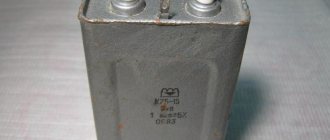
Tantalum capacitors
Passive components: Tantalum capacitors
| TYPE: | Type Explanation: | |||||
| SD | Molded Tantalum Tantalum capacitor (polar component) | |||||
| Size (inches) | Code | Component Thickness | Component size | Tape width | Component pitch in the ribbon | Qty per standard package (180 mm/7 inches) plastic tape |
| 3216 | A | 1.6 mm | 3.2 mm X 1.6 mm | 8 mm | 4 mm | 2000 |
| 3528 | B | 1.9 mm | 3.5 mm X 2.8 mm | 8 mm | 4 mm | 2000 |
| 6032 | C | 2.5 mm | 6.0 mm X 3.2 mm | 12 mm | 8 mm | 500 |
| 7343 | D | 2.8 mm | 7.3 mm X 4.3 mm | 12 mm | 8 mm | 500 |
| 1608 | J | 0.8 mm | 1.6 mm X 0.8 mm | 8 mm | 4 mm | 4000 |
| 2012 | P/R | 1.2 mm | 2.0 mm X 1.2 mm | 8 mm | 4 mm | 2500/3000 |
Types of SMD capacitors
Every radio amateur needs to understand the types of capacitors mounted using the surface-mount method. Such products may differ not only in capacity, but also in voltage, so ignoring the conditions for using parts can lead to their failure.
You might be interested in Features of measuring illumination in lux
Electrolytic components
Electrolytic SMD capacitors do not differ fundamentally from standard products. Such electronic components most often take the form of barrels, in which a thin metal rolled into a cylinder is located under an aluminum housing, and a solid or liquid electrolyte is located between it.
Electrolytic SMD capacitors
The main difference between such a part and a standard electrolytic cell is that its contacts are mounted on a flat dielectric substrate. Such products are very reliable in operation, especially convenient when it is necessary to install a new product with minimal time investment. In addition, during soldering the product does not overheat, which is very important for electrolytic capacitors.
Ceramic components
In ceramic elements, porcelain or similar inorganic materials are used as a dielectric. The main advantage of such products is their resistance to high temperatures and the ability to produce products of extremely small sizes.
Important! SMD ceramic capacitors are also installed by soldering onto a printed circuit board.
Visually, such an element, as a rule, resembles a small brick to which contact pads are soldered at the ends.
Ceramic SMD capacitors
Unlike radio components of standard sizes, SMD elements of small size are first glued to the board, and only then the leads are soldered. In production, ceramic products of this type are installed by special automatic machines.
Marking of tantalum SMD capacitors
Tantalum SMD capacitors are resistant to increased mechanical loads. Such products can also be made in the form of a small parallelepiped, to which contact leads are soldered on the sides. Tantalum is a very durable metal with high ductility. Foil made of this material can have a thickness of hundredths of a millimeter.
For your information! Due to the presence of certain physical properties based on tantalum, it is possible to produce radio components of the highest precision.
Tantalum capacitors
Tantalum capacitors, as a rule, have small housing sizes, so it is not always possible to apply full markings to products made in an “A” size housing. Knowing the designation features of radio components of this type, you can easily determine the rating of the product. The maximum permissible voltage in volts for tantalum products is indicated in Latin letters:
- G - 4;
- J - 6.3;
- A - 10;
- C - 16;
- D - 20;
- E - 25;
- V - 35;
- T - 50.
Note! The capacitance of products is indicated in microfarads after the letter “μ”, and the positive contact is indicated with a thick line.
Dimensions and types of SMD component housings
Two-pin components: rectangular, passive (resistors and capacitors)
The size designation consists of four digits. The first two correspond roundly to the length L in the accepted measurement system (either metric or inch), and the last two correspond to the width W.
| Size (inch system) | Size (Metric) | Size(mm) |
| 008004 | 0201 | 0.25×0.125 |
| 009005 | 03015 | 0.3×0.15 |
| 01005 | 0402 | 0.4×0.2 |
| 0201 | 0603 | 0.6×0.3 |
| 0402 | 1005 | 1.0×0.5 |
| 0603 | 1608 | 1.6×0.8 |
| 0805 | 2012 | 2.0×1.25 |
| 1008 | 2520 | 2.5×2.0 |
| 1206 | 3216 | 3.2×1.6 |
| 1210 | 3225 | 3.2×2.5 |
| 1806 | 4516 | 4.5×1.6 |
| 1812 | 4532 | 4.5×3.2 |
| 1825 | 4564 | 4.5×6.4 |
| 2010 | 5025 | 5.0×2.5 |
| 2512 | 6332 | 6.3×3.2 |
| 2725 | 6863 | 6.9×6.3 |
| 2920 | 7451 | 7.4×5.1 |
Two-pin components: cylindrical, passive (resistors and diodes) in MELF package
| frame | dimensions (mm) and other parameters |
| Melf (MMB) 0207 | L = 5.8 mm, Ø = 2.2 mm, 1.0 W, 500 V |
| MiniMelf (MMA) 0204 | L = 3.6 mm, Ø = 1.4 mm, 0.25 W, 200 V |
| MicroMelf (MMU) 0102 | L = 2.2 mm, Ø = 1.1 mm, 0.2 W, 100 V |
Two-terminal components: tantalum capacitors
| type | dimensions (mm) |
| A (EIA 3216-18) | 3,2 × 1,6 × 1,6 |
| B (EIA 3528-21) | 3,5 × 2,8 × 1,9 |
| C (EIA 6032-28) | 6,0 × 3,2 × 2,2 |
| D (EIA 7343-31) | 7,3 × 4,3 × 2,4 |
| E (EIA 7343-43) | 7,3 × 4,3 × 4,1 |
Two-terminal components: diodes (small outline diode, abbr. SOD)
| designation | dimensions (mm) |
| SOD-323 | 1,7 × 1,25 × 0,95 |
| SOD-123 | 2,68 × 1,17 × 1,60 |
Three-Terminal Components: Short Terminal Transistors (SOT)
| designation | dimensions (mm) |
| SOT-23 | 3 × 1,75 × 1,3 |
| SOT-223 | 6,7 × 3,7 × 1,8 |
| DPAK (TO-252) | package (three- or five-pin options) designed by Motorola for high-heat semiconductor devices |
| D2PAK (TO-263) | package (three-, five-, six-, seven- or eight-pin options), similar to DPAK, but larger in size (as a rule, the package dimensions correspond to the TO220 dimensions) |
| D3PAK (TO-268) | body similar to D2PAK, but even larger in size |
Multi-pin components: terminals in two lines on the sides
| designation | pin spacing (mm) |
| IC - with small-outline integrated circuit (SOIC) | 1,27 |
| TSOP - (English thin small-outline package) thin SOIC (thinner in height than SOIC) | 0,5 |
| SSOP - Seated SOIC | 0,65 |
| TSSOP - Thin Seated SOIC | 0,65 |
| QSOP - Quarter Size SOIC | 0,635 |
| VSOP - even smaller QSOP | 0.4; 0.5 or 0.65 |
Multi-pin components: terminals in four lines on the sides
| designation | pin spacing (mm) |
| PLCC, CLCC - IC in a plastic or ceramic package with leads bent under the package in the form of the letter J | 1,27 |
| QFP - (English quad flat package) - square flat IC packages | different sizes |
| LQFP - low profile QFP | 1.4mm high different sizes |
| PQFP - plastic QFP (44 or more pins) | different sizes |
| CQFP - ceramic QFP (similar to PQFP) | different sizes |
| TQFP - thinner than QFP | thinner than QFP |
| PQFN - power QFP | no leads, pad for radiator |
Multi-Pin Components: Pin Array
| designation | pin spacing (mm) |
| BGA - (English ball grid array) - an array of balls with square or rectangular pinouts | 1,27 |
| LFBGA - low profile FBGA, square or rectangular, solder balls | 0,8 |
| CGA - package with input and output pins made of refractory solder | different sizes |
| CCGA - Ceramic CGA | different sizes |
| μBGA - (micro-BGA) - ball array | distance between balls less than 1 mm |
| FCBGA - (English flip-chip ball grid array) an array of balls on a substrate, a crystal with a heat spreader is soldered to the substrate | different sizes |
| PBGA - ball array, crystal inside a plastic case | different sizes |
| LLP - leadless package | — |
YAGEO ceramic chip resistors
Nowadays it is difficult to find an electronic circuit without surface mount resistors. Yageo produces a wide range of ceramic chip resistors for a wide variety of applications. Resistors are available in common housing sizes and meet the stringent requirements of modern electronic equipment. The main parameters of some of the most popular series of Yageo chip resistors are summarized in Table 3.
Table 3. Basic parameters of some series of Yageo chip resistors
| Series | Name | Size | Pmax, W. | Vmax, V. | Temperature range, °С | R band | Accuracy, % | TKS** |
| R.C. | RC0100xR-07xxxxL | 1005 | 1/32 | 15 | -55…125 | 10 Ohm…1 MOhm | ±5 | ±250 ppm/°C (10 Ohm…1 MOhm) |
| RC0201xR-07xxxxL | 0201 | 1/20 | 25 | 10 Ohm…10 MOhm | ±1; ±5 | -100/+350 ppm/°C (1 Ohm…10 Ohm) ±200 ppm/°C (10 Ohm…10 MOhm) | ||
| RC0402xR-07xxxxL | 0402 | 1/16 | 50 | -55…155 | 1 Ohm…22 MOhm | ±0,5; ±1; ±5 | ±200 ppm/°C (1 Ohm...10 Ohm) ±200 ppm/°C (10 MOhm...22 MOhm) ±100 ppm/°C (10 Ohm...10 MOhm) | |
| RC0603xR-07xxxxL | 0603 | 1/10 | 1 Ohm…22 MOhm | |||||
| RC0805xR-07xxxxL | 0805 | 1/8 | 150 | 1 Ohm…22 MOhm | ||||
| RC1206xR-07xxxxL | 1206 | 1/4 | 200 | 1 Ohm…22 MOhm | ||||
| RC1210xR-07xxxxL | 1210 | 1/2 | 1 Ohm…22 MOhm | |||||
| RC1218xK-07xxxxL | 1218 | 1 | 1 Ohm…1 MOhm | |||||
| RC2010xK-07xxxxL | 2010 | 3/4 | 1 Ohm…22 MOhm | |||||
| RC2512xK-07xxxxL | 2512 | 1 | 1 Ohm…22 MOhm | |||||
| RC0805xR-7WxxxxL* | 0805 | 1/4 | 150 | 1 Ohm…100 Ohm | ±1; ±5 | ±200 ppm/°C | ||
| RC1206xR-7WxxxxL* | 1206 | 1/2 | 200 | 1 Ohm…100 Ohm | ||||
| RC2512xK-7WxxxxL* | 2512 | 2 | 1 Ohm…150 Ohm | |||||
| RT | RT0402xRx07xxxxL | 0402 | 1/16 | 50 | -55…125 | 10 Ohm…121 Ohm | ±0,05; ±0,1; ±0,25; ±0,5; ±1 | ±10; ±15; ±25; ±50 ppm/°C |
| RT0603xRx07xxxxL | 0603 | 1/10 | 75 | 5.1 Ohm…681 kOhm | ||||
| RT0805xRx07xxxxL | 0805 | 1/8 | 150 | 5.1 Ohm…1.5 MOhm | ||||
| RT1206xRx07xxxxL | 1206 | 1/8 | 200 | 5.1 Ohm…1.5 MOhm | ||||
| RT1210xRx07xxxxL | 1210 | 1/4 | 5.1 Ohm…1 MOhm | |||||
| RT2010xKx07xxxxL | 2010 | 1/2 | 10 Ohm…1 MOhm | |||||
| RT2512xKx07xxxxL | 2512 | 3/4 | 10 Ohm…1 MOhm | |||||
| RV | RV0805JR-07xxxxL | 0805 | 1/8 | 400 | -55…155 | 100 kOhm…10 MOhm | ±1; ±5 | ±200 ppm/°C (100 kOhm…10 MOhm) |
| RV1206JR-07xxxxL | 1206 | 1/4 | 500 | 100 kOhm…27 MOhm | ±5 | ±200 ppm/°C (100 kOhm…27 MOhm) | ||
| RV1206FR-07xxxxL | 100 kOhm…10 MOhm | ±1 | ||||||
| RV2512JK-07xxxxL | 2512 | 1 | 4.7 MOhm…16 MOhm | ±5 | ±200 ppm/°C (4.7 MΩ…16 MΩ) | |||
| *RC0805xR-7WxxxxL – new series of chip resistors are highlighted in red. **TCR – temperature coefficient of resistance for the range indicated in brackets. | ||||||||
Yageo chip resistors are designed to operate in the temperature ranges -55°C...125°C or -55°C...155°C and are available in package sizes from 1005 with a maximum power of 1/32 W to size 2512 with a power of up to 2 W . The RC series is designed for a wide range of applications. The RT series is distinguished by high accuracy of ratings and increased stability of parameters. The permissible voltage for the RC and RT series in housing sizes from 1206 is 200 V. The RV series is characterized by the presence of high-resistance resistors up to 27 MΩ and high permissible voltage values up to 500 V (resistors in housing 0805 allow a maximum voltage of up to 400 V). The dimensions of standard packages of the RC series chip resistors are shown in Table 4.
Table 4. Dimensions of thin-film chip resistors of the series
| Type | L, mm | W, mm | N, mm | I1, mm | I2, mm |
| RC0100 | 0,4 | 0,2 | 0,13 | 0,1 | 0,1 |
| RC0201 | 0,6 | 0,3 | 0,23 | 0,1 | 0,15 |
| RC0402 | 1,0 | 0,5 | 0,32 | 0,2 | 0,25 |
| RC0603 | 1,6 | 0,8 | 0,45 | 0,25 | 0,25 |
| RC0805 | 2,0 | 1,25 | 0,5 | 0,35 | 0,35 |
| RC1206 | 3,1 | 1,6 | 0,55 | 0,45 | 0,4 |
| RC1210 | 3,1 | 2,6 | 0,5 | 0,45 | 0,5 |
| RC1218 | 3,1 | 4,6 | 0,55 | 0,45 | 0,4 |
| RC2010 | 5,0 | 2,5 | 0,55 | 0,55 | 0,5 |
| RC2512 | 6,35 | 3,1 | 0,55 | 0,6 | 0,5 |
The designation system for Yageo chip resistors is shown in Figure 5.
Rice. 5. YAGEO chip resistor designation system
Of course, not every combination of letters and numbers in the designation system for resistors and capacitors will form the correct name (partnumber). The correctness of the name can be checked on the manufacturer’s website https://www.yageo.com/.
How to determine the capacitance, rating and voltage of SMD capacitors
Above, detailed information was provided on how to correctly determine the rating of SMD capacitors by marking. The main difficulty in performing such an operation is that the characters may be so small that they cannot be identified with the naked eye. In such a situation, it is recommended to use a magnifying glass or any other magnifying device with a suitable magnification, as well as install high-quality lighting in the place where such studies are carried out.
Radio amateur magnifier
Note! Sometimes the markings on the surface of the radio element are not readable or are completely missing, so every radio amateur should know how to determine the capacitance of an electrolytic capacitor without markings. To perform such work, you cannot do without a special measuring device.
How to determine the capacitance of an SMD capacitor without markings using a device
To obtain correct indicators, before starting to measure the capacitance of the capacitor, the radioelement must be completely discharged.
The voltage limit is measured on a capacitor, which is installed in an electronic circuit where the element can be safely connected to electrical voltage. After turning off the current source, measure the voltage at the contacts of the radio component. The resulting value in volts should be multiplied by 1.5 to obtain the exact value of this parameter.
Voltage can be measured with a cheap multimeter
SMD capacitors are very convenient for self-assembly of various circuits, and during automatic installation, thanks to them, it is possible to achieve maximum compactness in the arrangement of radio components. Knowing the principles of deciphering the designation of such elements, you can design and assemble even complex devices at home without any difficulty.
Sources
- https://amperof.ru/sovety-elektrika/sdm-kondensatory-bez-markirovki.html
- https://micpic.ru/spravochniki/159-razmery-smd-korpusov.html
- https://radio-magic.ru/smd-razmerj
- https://rusenergetics.ru/polezno-znat/smd-kondensatory-bez-markirovki-kak-opredelit
- https://www.RadioElementy.ru/articles/tantalovye-kondensatory/
- https://global-smt.ru/articles/surface-mount_technology/
Trimmer SMD resistors
Color coding of resistors
Products in this category are available in open and closed versions. Some models are equipped with a sealed housing to ensure long-term performance in conditions of high humidity (dust pollution of the atmosphere).
Trimmer SMD resistors in factory packaging
There is no single standard size for trimmer resistors. Manufacturers independently determine the labeling system and approve the rules with special regulations.