Rules for marking capacitors of constant capacity
When assembling homemade electronic circuits, you are inevitably faced with the selection of the necessary capacitors.
Moreover, to assemble the device, you can use capacitors that have already been used and have worked for some time in electronic equipment.
Naturally, before reuse, it is necessary to check capacitors, especially electrolytic ones, which are more susceptible to aging.
When selecting capacitors of constant capacity, it is necessary to understand the markings of these radio elements, otherwise, if there is an error, the assembled device will either refuse to work correctly or will not work at all. The question arises, how to read the capacitor markings?
A capacitor has several important parameters that should be taken into account when using them.
The first is the nominal capacitance of the capacitor . It is measured in fractions of Farad.
The second is permission. Or in other words, the permissible deviation of the nominal capacity from the specified one. This parameter is rarely taken into account, since household radio equipment uses radio elements with a tolerance of up to ±20%, and sometimes more. It all depends on the purpose of the device and the features of a particular device. This parameter is usually not indicated on circuit diagrams.
The third thing that is indicated in the marking is the permissible operating voltage . This is a very important parameter and you should pay attention to it if the capacitor will be used in high-voltage circuits.
So, let's figure out how capacitors are marked.
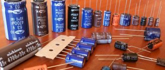
Some of the most popular capacitors that can be used are constant capacitors K73 - 17, K73 - 44, K78 - 2, ceramic KM-5, KM-6 and the like. Analogues of these capacitors are also used in imported electronic equipment. Their labeling differs from domestic ones.
Domestic-made capacitors K73-17 are polyethylene terephthalate film protected capacitors. The housing of these capacitors is marked with an alphanumeric index, for example 100nJ, 330nK, 220nM, 39nJ, 2n2M.
K73 series capacitors and their markings
Labeling rules.
Capacitances from 100 pF to 0.1 μF are marked in nanofarads, indicating the letter H or n .
The designation 100 n is the value of the nominal capacity. For 100n – 100 nanofarads (nF) – 0.1 microfarads (uF). Thus, a capacitor with index 100n has a capacity of 0.1 μF. Similar for other notations. For example: 330n – 0.33 µF, 10n – 0.01 µF. For 2n2 – 0.0022 µF or 2200 picofarads (2200 pF).
You can find markings like 47 H C. This entry corresponds to 47 n K and is 47 nanofarads or 0.047 μF. Similar to 22NS - 0.022 µF.
In order to easily determine the capacity, you need to know the designations of the main submultiple units - milli, micro, nano, pico and their numerical values. Read more about this here.
Also in the marking of K73 capacitors there are such designations as M47C, M10C. Here, the letter M conventionally stands for microfarad. The value 47 comes after M, i.e. the nominal capacitance is a fraction of a microfarad, i.e. 0.47 µF. For M10C - 0.1 µF. It turns out that capacitors marked M10C and 100nJ have the same capacity. The only differences are in the recording.
Thus, capacitance from 0.1 μF and above is indicated with the letter M , m instead of a decimal point, the insignificant zero is omitted.
The nominal capacity of domestic capacitors up to 100 pF is indicated in picofarads, placing the letter P or p after the number. If the capacitance is less than 10 pF, then put the letter R and two numbers. For example, 1R5 = 1.5 pF.
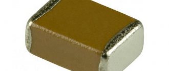
On ceramic capacitors (type KM5, KM6), which are small in size, usually only a numerical code is indicated. Here, look at the photo.
Ceramic capacitors with capacitance marked with a numerical code
For example, the numeric marking 224 corresponds to a value of 22,0000 picofarads, or 220 nanofarads and 0.22 µF. In this case, 22 is the numerical value of the denomination value. The number 4 indicates the number of zeros. The resulting number is the capacitance value in picofarads. Writing 221 means 220 pF, and writing 220 means 22 pF. If the marking uses a four-digit code, then the first three digits are the numerical value of the denomination value, and the last, fourth, is the number of zeros. So at 4722, the capacitance is 47200 pF - 47.2 nF. I think we've sorted this out.
The permissible deviation of the capacity is marked either with a percentage number (±5%, 10%, 20%) or with a Latin letter. Sometimes you can find the old tolerance designation encoded with a Russian letter. The permissible deviation of capacitance is similar to the tolerance for the resistance value of resistors.
Letter code of capacity deviation (tolerance).
So, if a capacitor with the following marking is M47C, then its capacity is 0.047 μF, and the tolerance is ±10% (according to the old marking with a Russian letter). It is quite difficult to find a capacitor with a tolerance of ±0.25% (as marked with a Latin letter) in household equipment, which is why a value with a larger error was chosen. Mainly in household equipment, capacitors with tolerance H , M , J , K . of the nominal capacity, like this 22n K , 220n M , 470n J.
Table for deciphering the conditional letter code of the permissible deviation of the capacity.
| Tolerance in % | B letter designation | |
| lat. | rus. | |
| ±0.05p | A | |
| ±0.1p | B | AND |
| ±0.25p | C | U |
| ±0.5p | D | D |
| ± 1,0 | F | R |
| ± 2,0 | G | L |
| ± 2,5 | H | |
| ± 5,0 | J | AND |
| ± 10 | K | WITH |
| ± 15 | L | |
| ± 20 | M | IN |
| ± 30 | N | F |
| -0. +100 | P | |
| -10. +30 | Q | |
| ± 22 | S | |
| -0. +50 | T | |
| -0. +75 | U | E |
| -10. +100 | W | YU |
| -20. +5 | Y | B |
| -20. +80 | Z | A |
Marking of capacitors by operating voltage.
An important parameter of the capacitor is also the permissible operating voltage. It should be taken into account when assembling homemade electronics and repairing household radio equipment. For example, when repairing compact fluorescent lamps, it is necessary to select a capacitor for the appropriate voltage when replacing failed ones. It would be a good idea to take a capacitor with a margin of operating voltage.
Typically, the value of the permissible operating voltage is indicated after the rated capacity and tolerance. It is designated in volts with the letter B (old marking) and V (new). For example, like this: 250V, 400V, 1600V, 200V. In some cases, the V is omitted.
Sometimes Latin letter coding is used. To decipher, you should use the table of letter coding of the operating voltage.
| N rated operating voltage, V | B letter code |
| 1,0 | I |
| 1,6 | R |
| 2,5 | M |
| 3,2 | A |
| 4,0 | C |
| 6,3 | B |
| 10 | D |
| 16 | E |
| 20 | F |
| 25 | G |
| 32 | H |
| 40 | S |
| 50 | J |
| 63 | K |
| 80 | L |
| 100 | N |
| 125 | P |
| 160 | Q |
| 200 | Z |
| 250 | W |
| 315 | X |
| 350 | T |
| 400 | Y |
| 450 | U |
| 500 | V |
Thus, we learned how to determine the capacitance of a capacitor by marking, and along the way we became acquainted with its main parameters.
Alphanumeric designation
If you disassemble old Soviet equipment, then everything will be quite simple - on the cases it says “22pF”, which means 22 picofarads, or “1000 uF”, which means 1000 microfarads. Old Soviet capacitors were usually large enough to allow such “long texts” to be written on them.
Global, so to speak, alphanumeric marking involves the use of letters of the Latin alphabet:
- p – picofarads,
- n – nanofarads
- m – microfarads.
At the same time, it is useful to remember that if we conventionally take picofarad as a unit of capacity (although this is not entirely correct), then the letter “p” will denote units, the letter “n” – thousands, the letter “m” – millions. In this case, the letter will be used as a decimal point. Here is a clear example, a capacitor with a capacity of 2200 pF, according to this system will be designated 2n2, which literally means “2.2 nanofarads”. Or a capacitor with a capacity of 0.47 µF will be designated m47, that is, “0.47 microfarads”.
Moreover, domestically produced capacitors have similar markings in Cyrillic, that is, picofarads are designated by the letter “P”, nanofarads by the letter “N”, microfarads by the letter “M”. But the principle is the same: 2H2 is 2.2 nanofarads, M47 is 0.47 microfarads. For some types of miniature capacitors, “μF” is designated by the letter R, which is also used as a decimal point, for example:
1R5 =1.5 µF.
Code marking of the capacity of imported capacitors
According to IEC standards, in practice there are four ways to encode the nominal capacity.
1. 3-digit encoding
The first two digits indicate the capacitance value in picofarads (pf), the last two digits indicate the number of zeros. When the capacitor has a capacitance of less than 10 pF, the last digit may be "9". For capacitances less than 1.0 pF, the first digit is “0”. The letter R is used as a decimal point. For example, code 010 is 1.0 pF, code 0R5 is 0.5 pF.
* Sometimes the last zero is not indicated.
2. 4-digit encoding
4-digit coding options are possible. But even in this case, the last digit indicates the number of zeros, and the first three indicate the capacity in picofarads (pF).
3. Capacitance marking in microfarads
The letter R may be used instead of the decimal point.
4. Mixed alphanumeric marking of capacity, tolerance, TKE, operating voltage
Unlike the first three parameters, which are marked in accordance with standards, the operating voltage has different alphanumeric markings from different companies.
Source: rcl-radio.ru
Capacitors with nonlinear temperature dependence
* Designation according to EIA standard, IEC in parentheses.
**Depending on the technologies that the company has, the range may be different. For example: for the Y5P group the norm is -55. +125 °C.
***According to EIA. Some use a different encoding.
* Tolerance 20%; a combination of two rings and a dot indicating a multiplier is possible.
** The color of the housing indicates the operating voltage.
* For capacitances less than 10 pF, the tolerance is ±2.0 pF. ** For capacitances less than 10 pF, tolerance ±0.1 pF.
To mark film capacitors, 5 colored stripes or dots are used. The first three encode the value of the nominal capacitance, the fourth - the tolerance, the fifth - the rated operating voltage.
How are large capacitors marked?
To correctly read the technical specifications of a device, some preparation is necessary. You need to start studying with units of measurement. To determine capacitance, a special unit is used - farad (F). The value of one farad for a standard circuit seems too large, so household capacitors are marked in smaller units. The most commonly used is mF = 1 µF (microfarad), which is 10 -6 farads.
In calculations, an off-label unit can be used - millifarad (1mF), which has a value of 10 -3 farads. In addition, designations can be in nanofarads (nF) equal to 10 -9 F and picofarads (pF) equal to 10 -12 F.
Capacitance markings for large capacitors are applied directly to the housing. In some designs, the markings may differ, but in general, you need to be guided by the units of measurement mentioned above.
Designations are sometimes written in capital letters, for example, MF, which actually corresponds to mF - microfarads. The marking fd is also found - an abbreviated English word farad. Therefore mmfd will correspond to mmf or picofarad. In addition, there are designations that include a number and one letter. This marking looks like 400m and is used for small capacitors.
In some cases, it is possible to apply tolerances, which are an acceptable deviation from the rated capacitance of the capacitor. This information is of great importance when, when assembling certain types of electrical circuits, capacitors with precise capacitance values may be required. If we take the marking 6000uF + 50%/-70% as an example, then the maximum capacitance value will be 6000 + (6000 x 0.5) = 9000 uF, and the minimum 1800 uF = 6000 - (6000 x 0.7).
If there are no percentages, you need to find the letter. Usually it is located separately or after the numeric designation of the container. Each letter corresponds to a specific tolerance value. After this, you can begin to determine the rated voltage.
With large capacitor housing sizes, voltage markings are indicated by numbers followed by letters or letter combinations in the form V, VDC, WV or VDCW. The WV symbols correspond to the English phrase WorkingVoltage, which means operating voltage. Digital readings are considered to be the maximum permissible capacitor voltage, measured in volts.
If there is no voltage marking on the device body, such a capacitor should only be used in low-voltage circuits. In an AC circuit, use a device designed specifically for this purpose. Capacitors designed for direct current cannot be used without the ability to convert the rated voltage.
The next step is to identify the positive and negative symbols that indicate the presence of polarity. Determining the positive and negative is of great importance, since incorrect determination of the poles can lead to a short circuit and even explosion of the capacitor. In the absence of special markings, the device can be connected to any terminals, regardless of polarity.
The pole designation is sometimes applied in the form of a colored stripe or a ring-shaped indentation. This marking corresponds to the negative contact in electrolytic aluminum capacitors, which are shaped like a tin can. In very small tantalum capacitors, these same symbols indicate positive contact. If there are plus and minus symbols, the color coding can be ignored.
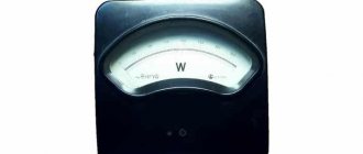
Capacitance measurement in resistance mode
Measurement in resistance mode
The multimeter switch should be set to resistance (ohmmeter) mode. In this mode, you can see if there is a break or short circuit inside the capacitor. To test a non-polar capacitor, the measurement range is set to 2 MOhm. For a polar product, a resistance of 200 Ohms is set, since at 2 MOhms charging will occur quickly.
The capacitor itself needs to be unsoldered from the circuit and placed on the table. Use the multimeter probes to touch the capacitor leads, observing the polarity. In non-polar parts, it is not necessary to observe plus and minus.
Measurement in resistance mode
When the probes touch the legs, the display will show a value that will increase. This is because the multitester will charge the component. After some time, the value on the screen will reach one - this means that the device is working. If 1 lights up immediately during testing, there is a break inside the device and it should be replaced. A zero value on the display indicates that a short circuit has occurred inside the capacitor.
If a non-polar capacitor is being tested, the value should be higher than 2. Otherwise, the device is not working.
Analog device
The above algorithm is suitable for a digital tester. When using an analog device, checking is even simpler - you only need to observe the movement of the arrow. The probes are connected in the same way, the mode is resistance testing. Smooth movement of the arrow indicates that the capacitor is working properly. The minimum and maximum values when connected indicate a breakdown of the electronic part.
It is important to note that testing in ohmmeter mode is carried out for parts with a capacitance above 0.25 µF. For smaller denominations, special LC meters or high-resolution testers are used
Explanation of capacitor markings
To decipher the marking, you need the meaning of the first two digits indicating the capacity. If the capacitor has very small dimensions that do not allow the capacity to be marked, it is marked according to the EIA standard, which is used for all modern products.
Designation of numbers
If the designation contains only two numbers and one letter, in this case the digital values correspond to the capacity of the device. All other markings are deciphered in their own way, in accordance with one design or another.
The third digit in the designation is a multiplier of zero. In this case, decryption is performed depending on the number located at the end. If such a digit is in the range 0-6, then a certain number of zeros are added to the first two digits. For example, you can take the marking 453, which will be deciphered as 45 x 10 3 = 45000.
When the last digit is 8, the first two digits are multiplied by 0.01. Thus, when labeled 458, the result is 45 x 0.01 = 0.45. If the 3rd digit is 9, then the first two digits must be multiplied by 0.1. As a result, the notation 459 is converted to 45 x 0.1 = 4.5.
After determining the capacity, you need to determine the unit to measure it. The smallest capacitors - ceramic, film and tantalum - have a capacitance measured in picofarads (pF), amounting to 10 -12. To measure the capacitance of large capacitors, microfarads (μF) equal to 10 -6 are used. Units of measurement can be designated by letters: p – picofarad, u – microfarad, n – nanofarad.
Letter designation
After the numbers, it is necessary to decipher the letters included in the marking. If a letter is present in the first two characters, it can be decrypted in several ways. If the letter R is present, it is replaced by a comma, which is used for the decimal fraction. Decoding the 4R1 marking will look like 4.1 pF.
If there are letters p, n, u, corresponding to pico-, nano- and microfarads, a decimal point is also replaced. The n61 designation reads 0.61 nF, the 5u2 marking corresponds to 5.2 μF.
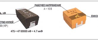
Marking of ceramic capacitors
Ceramic capacitors have a flat round shape and two contacts. On the case, in addition to the main indicators, the tolerance for deviations from the nominal capacity is indicated. For this purpose, a specific letter is used, placed immediately after the digital designation of the container. For example, the letter “B” corresponds to a deviation of + 0.1 pF, “C” - + 0.25 pF, D - + 0.5 pF. These values apply for capacitances less than 10 pF. For capacitors with a capacitance of more than 10 pF, the letter designations correspond to a certain percentage of deviations.
Mixed alphanumeric markings
The tolerance marking may consist of an alphanumeric designation according to the “letter-number-letter” scheme. The first letter character corresponds to the minimum temperature, for example, Z = 10 degrees, Y = -30 0 C, X = -55 0 C. The second numeric character is the maximum temperature.
The numbers correspond to the following indicators: 2 – 45 0 C, 4 – 65 0 C, 5 – 85 0 C, 6 – 105 0 C, 7 – 125 0 C. The value of the third letter symbol means the changing capacitance of the capacitor, within the range between minimum and maximum temperature. More accurate indicators include “A” with a value of + 1.0%, and less accurate indicators include “V” with a value from 22 to 82%. The most commonly used "R" is 15%.
General characteristics of film capacitors
Film capacitors are a structure in which the dielectric is made in the form of a film. During the production process, a metal film (metal film capacitors) is sprayed onto the dielectric film or foil is pressed onto it (foil capacitors) (Figure 1a). Metal film capacitors are smaller in size, but their electrical properties are also somewhat worse.
In the simplest case, the resulting film is rolled into a roll (Figure 1b); this design is easy to manufacture, but has a high parasitic inductance. In order to reduce inductance, capacitors for high-frequency applications are manufactured in the form of a multilayer extruded structure (Figure 1c), which is essentially a set of capacitors connected in parallel.
Rice. 1. Capacitor design
There are technologies in which metal foil is used in conjunction with metallized film.
An important advantage of film capacitors is their ability to self-heal (Figure 2). If a breakdown of the dielectric occurs during an overvoltage, then a current begins to flow through the breakdown site, which will heat the metal film near the breakdown site. Gradually heating up, the metal melts and evaporates. As a result, the dielectric strength is restored.
Rice. 2. Breakdown and self-healing of the film capacitor
It is worth noting that the concept of “film capacitor” describes the technological and design side of the component, and the final technical parameters mainly depend on the type of dielectric used. There are: polypropylene film, polystyrene film, polyethylene terephthalate (polyester film), polycarbonate and fluoroplastic film capacitors.
Film capacitors with different types of dielectric differ in their properties from each other and from other types of capacitors (Table 1).
Table 1. Comparative characteristics of capacitors
| Type | tg d | Rizol, Mom | Absorption coefficient, % | TKE, 10-6/°С | Russian capacitor series |
| Polystyrene | 0,001…0,0015 | 100000 | <0,1 | -200 | Foil: K70; metallized: K71 |
| Polypropylene | 0,002 | 50000 | <0,5 | -200…100 | K78 |
| Polyethylene terephthalate | 0,01…0,1 | 10000 | ≈0,2…0,8 | -200…400 | Foil: K74; metallized: K73 |
| Aluminum electrolytic | 0.1…0.5 (50 Hz) | – | 5…6 | – | K50 |
| Tantalum | 0.06…0.3 (50 Hz) | – | 2…5 | – | K51, K53 |
| Ceramic | 0,001…0,0035 | 10000 | 5…15 | 30 (NPO) | K10, K15 |
A feature of polypropylene capacitors is the low value of the loss tangent (0.001) over a wide range of temperatures and frequencies. These capacitors have small overall dimensions and the ability to operate them at high voltage amplitudes. In addition, their absorption coefficient, as a rule, does not exceed 0.5%.
Polystyrene capacitors belong to the low-loss capacitors (tgd about 0.001). They have a very high insulation resistance (10,000 MΩ), low absorption coefficient (0.1%) and high temperature stability. Their self-discharge current is so small that most of the leakage can be generated by surface currents (currents flowing through the surface of the capacitor).
Polyethylene terephthalate capacitors have high dielectric constant and strength. However, tgd is no more than 0.1, and the insulation resistance is up to 10,000 MOhm. Lavsan is a polar dielectric, therefore Lavsan capacitors have a high absorption coefficient (up to 0.8%).
Other markings
The markings on the capacitor body allow you to determine the voltage value. The figure shows special symbols that correspond to the maximum permissible voltage for a particular device. In this case, parameters are given for capacitors that can only be operated at constant current.
In some cases, marking capacitors is greatly simplified. For this purpose, only the first digit is used. For example, zero will mean a voltage below 10 volts, a value of 1 - from 10 to 99 volts, 2 - from 100 to 999 V, and so on, according to the same principle.
Other markings apply to capacitors that were manufactured much earlier or intended for special purposes. In such cases, it is recommended to use special reference books to avoid serious mistakes when assembling the electrical circuit.
Source: electric-220.ru
How to decipher the markings of a capacitor and find out its capacity?
Basic information about the characteristics of capacitors, which are components of almost all electronic circuits, is usually placed on their cases. Depending on the standard size of the element, manufacturer, production time, the data applied to the electronic device constantly changes not only in composition, but also in appearance.
With a decrease in the size of the case, the composition of alphanumeric designations was changed, encoded, and replaced by color markings. The variety of internal standards used by manufacturers of radio-electronic elements requires certain knowledge to correctly interpret the information printed on an electronic device.
Designation in diagrams
In general, when repairing and re-soldering modern SMD printed circuit boards, it is most convenient when you still have a diagram at hand, looking at which it is much easier to understand what is installed, to find out the location of a certain part, because an SMD capacitor in appearance may not differ at all from the same transistor. The designations of these parts in the circuits remained the same as they were before the arrival of chips on the market, and therefore the capacity and other necessary characteristics can also be easily found by a radio amateur who has not encountered SMD components.
Why is labeling needed?
The purpose of marking electronic components is to allow them to be accurately identified. Capacitor markings include:
- data on the capacitance of the capacitor - the main characteristic of the element;
- information about the rated voltage at which the device remains operational;
- data on the temperature coefficient of the capacitance, which characterizes the process of changing the capacitance of the capacitor depending on changes in ambient temperature;
- percentage of permissible deviation of the capacity from the nominal value indicated on the device body;
- release date.
For capacitors, when connecting which polarity must be observed, information must be provided that allows the element to be correctly oriented in the electronic circuit.
The marking system for capacitors produced at enterprises that were part of the USSR had fundamental differences from the marking system used at that time by foreign companies.
Some notes and tips on working with capacitors
It must be remembered that capacitors with a higher rated voltage should be selected as the ambient temperature increases, creating a larger voltage reserve to ensure high reliability. If the maximum constant operating voltage of the capacitor is specified, this refers to the maximum temperature (unless otherwise stated). Therefore, capacitors always operate with a certain margin of safety. And yet, it is desirable to ensure that their actual operating voltage is at a level of 0.5-0.6 nominal.
Marking of domestic capacitors
All post-Soviet enterprises are characterized by fairly complete labeling of radioelements, allowing for minor differences in designations.
The first and most important parameter of a capacitor is capacitance. In this regard, the value of this characteristic is placed in first place and is encoded with an alphanumeric designation. Since the unit of measurement of capacitance is the farad, the letter designation contains either the symbol of the Cyrillic alphabet “F” or the symbol of the Latin alphabet “F”.
Since the farad is a large value, and the elements used in industry have much smaller values, the units of measurement have a variety of diminutive prefixes (mili-, micro-, nano- and pico). Letters of the Greek alphabet are also used to designate them.
- 1 millifarad is equal to 10 -3 farads and is denoted 1mF or 1mF.
- 1 microfarad is equal to 10 -6 farads and is designated 1 µF or 1F.
- 1 nanofarad is equal to 10 -9 farads and is denoted 1nF or 1nF.
- 1 picofarad is equal to 10 -12 farads and is denoted 1pF or 1pF.
If the capacity value is expressed as a fraction, then the letter indicating the dimension of the units of measurement is placed in place of the comma. Thus, the designation 4n7 should be read as 4.7 nanofarads or 4700 picofarads, and the inscription like n47 corresponds to a capacity of 0.47 nanofarads or 470 picofarads.
In the case where the capacitor does not have a rating indicated, the integer value indicates that the capacitance is indicated in picofarads, for example, 1000, and the value expressed as a decimal fraction indicates the rating in microfarads, for example, 0.01.
The capacitance of the capacitor indicated on the case rarely corresponds to the actual parameter and deviates from the nominal value within a certain range. The exact capacitance value sought when making capacitors depends on the materials used to manufacture them. The spread of parameters can range from thousandths to tens of percent.
The value of the permissible deviation of the capacitance is indicated on the capacitor body after the nominal value by placing a letter of the Latin or Russian alphabet. For example, the Latin letter J (Russian letter I in the old designation) indicates a deviation range of 5% in one direction or another, and the letter M (Russian V) - 20%.
Such a parameter as the temperature coefficient of capacitance is included in the marking quite rarely and is applied mainly to small-sized elements used in electrical circuits of timing circuits. For identification, either an alphanumeric or color notation system is used.
There is also a combination of letter and color markings. Its options are so diverse that to accurately determine the value of this parameter for each specific type of capacitor, you need to refer to GOSTs or reference books on the corresponding radio components.
Rated voltage
The voltage at which the capacitor will operate for a specified service life while maintaining its characteristics is called the rated voltage. For capacitors of sufficient size, this parameter is applied directly to the body of the element, where the numbers indicate the rated voltage value, and the letters indicate in which units of measurement it is expressed.
For example, the designation 160V or 160V indicates that the nominal voltage is 160 volts. Higher voltages are indicated in kilovolts - kV. On small-sized capacitors, the rated voltage is encoded with one of the letters of the Latin alphabet. For example, the letter I represents a nominal voltage of 1 volt, and the letter Q represents 160 volts.
Date of issue
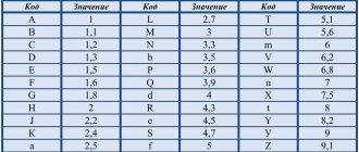
According to “GOST 30668-2000 Electronic products. Marking”, letters and numbers indicating the year and month of production are indicated.
“4.2.4 When indicating the year and month, first indicate the year of manufacture (the last two digits of the year), then the month - in two digits. If the month is indicated by one digit, then a zero is placed in front of it. For example: 9509 (1995, September).
4.2.5 For products whose overall dimensions do not allow the year and month of manufacture to be indicated in accordance with 4.2.4, the codes given in tables 1 and 2 should be used. The marking codes given in table 1 are repeated every 20 years.”
The date when a particular production was carried out can be displayed not only in the form of numbers, but also in the form of letters. Each year has a relationship with a letter from the Latin alphabet. The months from January to September are designated by numbers from one to nine. The month of October has a relationship with the number zero. November corresponds to the Latin letter N, and December – D.
| Year | Code |
| 1990 | A |
| 1991 | B |
| 1992 | C |
| 1993 | D |
| 1994 | E |
| 1995 | F |
| 1996 | H |
| 1997 | I |
| 1998 | K |
| 1999 | L |
| 2000 | M |
| 2001 | N |
| 2002 | P |
| 2003 | R |
| 2004 | S |
| 2005 | T |
| 2006 | U |
| 2007 | V |
| 2008 | W |
| 2009 | X |
| 2010 | A |
| 2011 | B |
| 2012 | C |
| 2013 | D |
| 2014 | E |
| 2015 | F |
| 2016 | H |
| 2017 | I |
| 2018 | K |
| 2019 | L |
Location of markings on the body
Labeling plays an important role on any product. It is often placed on the first line on the case and has a capacity value. The same line involves placing the so-called tolerance value on it. If both applications do not fit on this line, then this can be done on the next one.
A similar system is used to apply film-type condensates. The arrangement of elements must be located according to certain regulations, which are produced by GOST or TU for an element of an individual type.
Color marking of domestic radioelements
In the production of lines with so-called automatic types of installation, color application appeared, as well as its direct significance in the entire system.
Today, the most commonly used application is using four colors. In this case, we resorted to using four stripes. So, the first strip together with the second represents the capacitance value in so-called picofarads. The third band indicates the deviation that can be allowed. And the fourth band, in turn, means the voltage of the nominal type.
We give you an example of how this or that element is designated - capacity - 23 * 106 picofarads (24 F), permissible deviation from the nominal value - ± 5%, rated voltage - 57 V.
Marking of imported capacitors
To date, the standards that have been adopted from the IEC apply not only to foreign types of equipment, but also to domestic ones. This system involves applying a code type marking to the product body, which consists of three direct numbers.
The two numbers that are located from the very beginning indicate the capacity of the item and in units such as picofarads. The number that is located third in order is the number of zeros. Let's look at this using the example of 555 - that's 5,500,000 picofarads. In the event that the capacity of the product is less than one picofarad, then the number zero is indicated from the very beginning.
There is also a three-digit type of encoding. This type of application is used exclusively for parts that are highly precise.
Color coding of imported capacitors
The designation of names on an object such as a capacitor has the same production principle as on resistors. The first stripes on two rows indicate the capacity of this device in the same measurement units. The third stripe has a designation indicating the number of immediate zeros. But at the same time, the blue color is completely absent; blue is used instead.
It is important to know that if the colors are the same in a row, then it is advisable to create gaps between them so that it is clearly understood. Indeed, in another case, these stripes will merge into one.
Marking of smd components
So-called SMD components are used for surface mounting and are extremely small in size. Accordingly, for this reason, they are marked with minimal dimensions. As a result, there is a system for abbreviating both numbers and letters. The letter designates the capacity of a particular object in units of picofarads. As for the number, it denotes the so-called multiplier to the tenth power.
Very common electrolytic capacitors can have values of the main type of parameter on their immediate body. This value is a fraction in decimal type.
How to correctly determine the resistance of a resistor with a multimeter
To accurately measure the resistance of a specific resistor, you do not need to have special knowledge in electrical engineering. To do this you will need a set of tools and strict adherence to the instructions.
To work you will need:
- Multimeter;
- Soldering iron;
- Resistors.
First of all, you need to make sure that the multimeter is working properly. Check the quality of the contacts of the measuring probes with the conductors, as well as the consistency of the readings on the device display.
Further, if the resistor, which must be checked, is part of any microcircuit, it needs to be unsoldered. This is due to the fact that the readings on the measuring device will correspond to the resistance of all elements of the circuit.
After the resistor has been removed and the multimeter has been tested for serviceability, you can proceed to measuring the resistance. To do this, we find on the multimeter scale the symbols for measuring resistance. They are represented by the Greek letter omega. And having presumably determined the resistance of the resistor, we set the desired value on the multimeter.
For example, if a resistor with a resistance of supposedly 1 kOhm (1000 Ohms) to 10 kOhms (10000 Ohms), select a slightly larger value on the multimeter (20 kOhms). If the value is selected inappropriately, the multimeter display will show one.