A coaxial cable (coaxial pair) is a conductor that consists of a central core and a screen. They are separated by insulating material or an air chamber, but located on the same axis. It transmits radio frequency electrical signals. The difference from a shielded wire is a uniform cross-section in the direction of one axis, the manufacture of an insulating layer from higher quality materials, and better conductor quality. All dimensional characteristics are standardized by industry standards.
This product can be thin or thick. Select it in accordance with the network parameters. The slim one has a diameter of 5 mm, it is flexible, easy to use and versatile. It connects to the computer's network adapter cards and transmits the signal over a distance of 185 m without interference or attenuation. The thin cable is equipped with copper cores.
A thick coaxial cable has less flexibility in bending; its diameter is 10 mm. Its name is often listed as "standard Ethernet", due to its use in network architecture. The copper core has a larger cross-section. The signal range is 500 m, so it can be used to connect small networks consisting of a thin analogue.
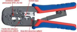
To connect to a thick type of cable, a special device is used - a transceiver, which is equipped with a vampire (piercing) tap connector - “vampire tooth” or “piercing coupler”. It is able to pass through the insulation and establish a connection to the conductor. To connect the transceiver to the network adapter, you need to connect the first wire to the AUI connector of the board. It is called the DIX connector.
As the cross-sectional area of the cable increases, the complexity of its installation increases. Thin has advantages such as ease of operation, low cost, and flexibility. Thick in this regard is inferior to its counterpart, especially when it comes to laying routes through pipes and gutters. Its advantage is the ability to transmit a signal over a greater distance.
Advantages and disadvantages
The high popularity of the cable is due to its advantages:
- slight attenuation;
- stability of operation at different signal frequencies;
- wide bandwidth;
- safety and ease of installation;
- low price, light weight, flexibility, ease of use.
Operational disadvantages include:
- lower bandwidth compared to optical fiber;
- the need for connectors, the complexity of their installation and high cost;
- the cost of installation work with a thick cable;
- more complex wiring compared to twisted pair;
- susceptibility to mechanical damage.
Marking
Laying and connecting a coaxial antenna cable does not require any special skills or knowledge in this area. It is much more difficult to choose an electrical cable taking into account the specifics of television transmission of information. To understand which option is better to buy, it is recommended to consider the labeling and initial data of the products.
Coaxial cable brands:
- RG – 6 has gained popularity due to its low price and good properties. Suitable for interior work.
- RG-59, a thin cable that receives all types of signals, loses its characteristics at a distance of more than 190 m.
- PK 75 from the Russian manufacturer provides a copper core and braid, as well as a double protective stage made of tinned copper and aluminum.
- The SAT 703 brand has a characteristic impedance of 75 Ohms, as well as a double screen.
- SAT 50 from the Italian brand has an enhanced degree of protection.
- DG 113 is the most expensive antenna coaxial cable, but increased shielding values transmit high-level signals.
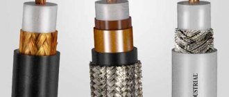
Components
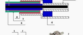
The coaxial cable includes:
- 4 – shells used as insulating and protective layers. They are made from light-stabilized polyethylene (PE), PVC, twisted fluoroplastic tape;
- 3 – the outer conductor (screen) is made in the form of a braid, foil with an outer coating of aluminum, corrugated tubes, twisted metal strips (copper, aluminum- and copper-based alloys);
- 2 – insulating layer, represented by a solid or semi-air dielectric filling, which ensures the alignment of the outer and inner conductor. It can be made of PE, foamed PE, solid fluoroplastic, fluoroplastic tape, tubular cord, washer, etc.;
- 1 – internal conductor, represented by a single straight or spiral cable, stranded conductor, tube made of copper, an alloy based on it, an aluminum alloy, copper-plated steel or aluminum, silver-plated copper.
Alignment minimizes electromagnetic energy loss due to radiation and provides protection against interference. This is due to the concentration of both components of the electromagnetic field in the space between the conductors and the impossibility of them leaving the cable. In reality, such deviations can occur, so the indicators are not ideal, and the main part of the signal is conducted through the core.
Transcript example
Description
High voltage coaxial cable, used to carry large amounts of power rather than signals.
The central core may be made of solid wire or of several stranded copper wires; while the outside may be woven mesh, rolled sheet, or corrugated copper or aluminum tubing. In the latter case, you will get a semi-rigid cable.
Due to the need to handle increasingly higher frequencies and the digitization of transmissions, in recent years the use of coaxial cable has been gradually replaced by fiber optic cable, especially over distances exceeding several kilometers, since the latter's capacity is much higher.
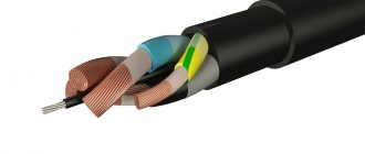
The choice of design affects the size, flexibility and electrical properties of the cable. Coaxial cable consists of a strand of copper wire surrounded by an insulator (or dielectric), a braided metal screen or shield, and an outer sheath.
The core of a coaxial cable carries electronic signals that make up information. This core can be solid (usually copper) or wire. The core is surrounded by a dielectric insulating layer, separating it from the wire mesh. The braided mesh acts as a ground, protecting the core from electrical noise and distortion from adjacent wires. The core and mesh must be separated from each other. If they touched, a short circuit would occur, and noise or signals lost in the grid would travel along the copper wire.
Shielding involves a braided or mesh of metal (or other material) that surrounds the cables. The shield protects the transmitted data by absorbing interference so that it does not pass through the cable and data corruption does not occur. A cable containing an insulating foil and a shielding layer of metal braid is called a double shield cable. For strong interference there is quad shielding. This screen consists of two insulating sheets and two layers of woven metal screen.
A short circuit occurs when two wires or a wire and ground come into contact. This contact causes current (or data) to flow forward along an unwanted path. In a normal electrical installation, a short circuit will cause arcing and blow the fuse or circuit breaker. With electronic devices using low voltage, the effect is smaller and barely noticeable. These low voltage short circuits cause the device to fail and typically transmitted data is lost.
A non-conductive outer jacket (usually made of rubber, Teflon, or plastic) surrounds the entire cable to prevent possible electrical shock.
Coaxial cable is more resistant to interference and attenuation than twisted pair; For this reason, there was a time when it was most used.
The wire mesh absorbs stray electronic signals so they do not affect the data transmitted over the internal cable. For this reason, coaxial cable is a good choice for long distances and reliable transmission of large amounts of data using a simple system.
In coaxial cables, the fields caused by the currents that circulate through the inner and outer cable cancel each other out.
Characteristics of coaxial cable
The main characteristics of coaxial cable include:
| probability of a collision | 10^(-9)…10^(-7); |
| frequency | more than 50 MHz (video, path length - 2 km), more than 400 MHz (radio, length - up to 50 km with an amplifier); |
| price | small compared to fiber optics; |
| interference immunity | high, including electromagnetic; |
| transferability | analog and digital signals; |
| bandwidth | wide; |
| the ability to transmit a signal over a distance without interference | 100-1000 m; |
| degree of radio emission | small. |
Optical digital connection
In an optical digital connection, data is transmitted through a fiber optic cable (the fibers of which can be made of plastic, glass or quartz) using light. In this case, noise from the source is not transferred to the DAC circuit, as can happen with a coaxial one, so it is reasonable to use it when connecting the device directly to the DAC of a soundbar or AV receiver.
Traditionally, in DC systems, optical cables are used to transmit compressed multi-channel audio in Dolby Digital and DTS formats. Those with a Toslink connector (Toshiba Link) connect to the corresponding ports of the source and AV receiver. A good starting option is the QED Performance Graphite Optical cable.
Many manufacturers have moved to HDMI as the primary connector type, but optical outputs are still regularly found on devices such as game consoles, Blu-ray players, set-top boxes and televisions. The corresponding inputs can be found on the amplifier or DAC side - for example, in sound bars or AV receivers.
As with coaxial connections, one of the problems with optical connections is the lack of bandwidth to transmit lossless audio formats, such as Dolby TrueHD or DTS-HD Master Audio, which contain most soundtracks on Blu-ray discs. In addition, the optical connection is not capable of transmitting more than two uncompressed channels to the PCM. Finally, the optical cable can be damaged if it is bent too much.
Classification
Types of coaxial cables by application:
- for aviation;
- for cable TV;
- for household appliances;
- for space technology;
- for computer networks;
- for communication.
Characteristic impedance may differ from the values indicated in the classification; for convenience, cables are divided into groups. In Russia there are five classes, and in international standards there are three. Analog audio equipment often uses conductors that are not standardized. Depending on the wave resistance there are:
- 50 Ohm - the cable is the most popular and is used in radio engineering. It transmits radio signals with maximum power and electrical strength with minimal losses;
- 75 Ohm is the second most popular conductor, used in TV systems. It is characterized by mechanical strength and low cost, and is used with low power but a significant network length. His losses are somewhat higher;
- 100 Ohm – used in pulse technology and special purposes;
- 150 Ohm – is an analogue with increased resistance;
- 200 Ohm - characterized by the highest resistance, provided only by Russian Federation standards.
Classification based on insulation diameter divides coaxial cable into groups:
- subminiature – up to 1 mm;
- miniature – 1.5-2.95 mm;
- medium-sized – 3.7-11.5 mm;
- large-sized - more than 11.5 mm.
According to the type of screen, the wire is divided into:
- from a tube made of metal;
- solid;
- with tinned braid;
- with double and multi-layer braid, additional layer;
- with single layer braid;
- standard screen;
- radiating conductor (with a specially reduced but controlled degree of shielding).
Depending on flexibility there are:
- hard;
- semi-rigid;
- flexible;
- especially flexible cable.
Installation rules
The presented wires are quite flexible, so the installation process will not be difficult. It is important to remember that the turning radius during installation cannot exceed 12 times the bending value of the cable sheath.
If the master does not follow the recommendations, then the bend will gradually destroy the integrity of the shell. The central core will push through the dielectric layer, so a short circuit will occur on the screen. It is important not to hang the cable on a nail , otherwise it will stretch under its own weight and lead to a break in the central core.
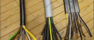
It is necessary to properly cut the ends in order to attach the connectors; the accuracy of the operation of electrical devices depends on this. You should do it this way:
- Cut the cable at right angles to the sheath.
- Insert the stripped end of the wire into a special tool to remove the insulating layer.
- Squeeze the tool, as a result the insulation will be removed and the copper core will be exposed.
- Clamp the cable well and turn it several times.
- Make a few more turns using the ring without releasing the tool.
You might be interested in this Marking and characteristics of VVG copper multicore cable
After this procedure, the master receives a completely stripped cable, which is ready for further connection.
The sheath protects against moisture penetration into the copper wire and prevents various external damages during the entire period of operation. The cable should never be laid underground or in damp places. Water seeps into the protective shell, causing its gradual destruction, oxidation and short circuit of the central rod. But it can be used on the surface with low humidity levels, as well as in rainy weather.
To prevent moisture from penetrating inside, you need to carefully treat the joints. Silicone sealants are used for this. Electrical tape and plasticine are not proven methods of protection. You can also buy connectors that are resistant to the negative effects of moisture. Connections made by soldering can change the level of characteristic impedance.