TIA/EIA-568-B
is a set of three telecommunications standards released by the Telecommunications Industry Association in 2001, which replaced the outdated TIA/EIA-568-A standard. These standards describe the construction of telecommunications structured cabling systems in buildings.
These standards are best known for two tables T568A and T568B, which describe the connection of twisted pair cable conductors to the pins of 8P8C connectors (often erroneously called RJ-45) when organizing an Ethernet network.
Tables T568 [edit | edit code ]
Straight through cable [edit | edit code ]
When connecting Ethernet terminal equipment (such as a computer, network printer) to switching equipment (hub/switch/router), both ends of the cable are crimped equally (so-called straight cable). In clause 6.2.1 of the standard, for horizontal connections, table T568A is given first, and also, as an option, if necessary, it is allowed to use table T568B. For the USA, federal law (NCS, FTR 1090-1997) allows switching only according to table T568A. In practice, during the construction of SCS and the production of patch cords, table T568B is more often used (including some American manufacturers, in particular AMP).
EIA/TIA-568A option:
Pin No. - core color - Pin No. on the other end of the cable
| 1 | = = = = | = = = = | 1 green-white |
| 2 | ==== | ==== | 2 green |
| 3 | = = = = | = = = = | 3 orange-white |
| 4 | ==== | ==== | 4 blue |
| 5 | = = = = | = = = = | 5 blue-white |
| 6 | ==== | ==== | 6 orange |
| 7 | = = = = | = = = = | 7 brown-white |
| 8 | ==== | ==== | 8 brown |
and according to the EIA/TIA-568B standard:
Pin No. - core color - Pin No. on the other end of the cable
| 1 | = = = = | = = = = | 1 orange-white |
| 2 | ==== | ==== | 2 orange |
| 3 | = = = = | = = = = | 3 green-white |
| 4 | ==== | ==== | 4 blue |
| 5 | = = = = | = = = = | 5 blue-white |
| 6 | ==== | ==== | 6 green |
| 7 | = = = = | = = = = | 7 brown-white |
| 8 | ==== | ==== | 8 brown |
Crossover cable [edit | edit code ]
The use of a straight cable is designed so that one (and only one) of the ends of the cable is connected to the switch port, and the crossing of the Rx (receive) and Tx (transmit) signal lines is performed inside the port. When directly connecting two pieces of network equipment (for example, two computers or two hubs), it is necessary to use a special, so-called. cross, cable (English crossover). For such a cable, the crossing of the Rx and Tx lines is performed by crimping one of the ends of the cable.
Since the tables T568A and T568B differ from each other precisely in that pairs 1-2 and 3-6 are swapped in them, to make a crossover cable for a 10BASE-T and 100BASE-T network, it is enough to crimp one end of the cable according to one table, and the other end is on the other.
It should be remembered that devices that support the 1000BASE-T standard transmit data over all four pairs of the cable, with each pair transmitting a signal in both directions at once, and the frames are marked in a special way, which prevents them from being assembled incorrectly by the receiving device. Therefore, any end of a cable designed to work with any 1000BASE-T devices, be it switches or nodes, can be crimped according to any given scheme.
How to connect an internet outlet
Well guys, remember, I wrote about sockets behind the TV. there were three of them - an ordinary electric one, for an antenna, and the last one was the Internet, which is very popular nowadays. I already wrote about the first two, just follow the links, but about the last one, “tailored” for computers, I somehow kept putting it off. Today I want to correct this injustice and post complete instructions for connecting. I have a LEZARD socket, but it will be useful for everyone to look at it, because the principle is the same for everyone. As usual there will be photo and video instructions. So bookmark it...
First, let's look at the Internet outlet itself. This is a plastic type that fits into a regular socket box. but it connects to an Internet cable, that is, there are no electrical wires there.
On the outside of this socket there is a connector for an RJ45 connector, which is where we then insert the wire from the network card of a computer, laptop or TV (SMART TV). Hangs on the wall to hide wires (which are embedded in the wall) and make it more aesthetically pleasing. Everything is hidden, everything is beautiful - this is the main purpose. I think now it becomes clear why it is needed!
Cable bending radius [edit | edit code ]
The bending radius of patching and hardware cables (cords) during operation [2] is not less than:
- 4 external cable diameters - for 4-pair cords based on unshielded and shielded twisted pair conductors;
- 1 inch (
25 mm) - for fiber optic cords.
TIA/EIA-568-B
is a set of three telecommunications standards released by the Telecommunications Industry Association in 2001, which replaced the outdated TIA/EIA-568-A standard. These standards describe the construction of telecommunications structured cabling systems in buildings.
These standards are best known for two tables T568A and T568B, which describe the connection of twisted pair cable conductors to the pins of 8P8C connectors (often erroneously called RJ-45) when organizing an Ethernet network.
Crimping a twisted pair cable into a connector
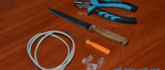
To crimp the ends on the connector, special pliers are used, which can cost from 6 to 10 dollars, depending on the manufacturer. When using such a tool, high-quality contacts are obtained, although this can be done using wire cutters and a screwdriver.
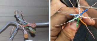
First, you need to remove the protective insulation from the cable, at a distance of 7-8 cm from the end of the cable. The cable contains four pairs of wires of different colors, twisted in pairs. There are cables with a thin shielding braid. It won't be needed, so you can simply bend it to the side. All pairs are untwisted, and the wires are aligned, spread apart and laid out according to pattern “B”.
The separated wires are clamped between the thumb and forefinger. At the same time, you need to make sure that the wires are straight and tightly pressed to one another. If the wires are of different lengths, they can be aligned with wire cutters, leaving a total of 10-12 mm in length. If you take the connector and try it on, the insulation of the wires should start slightly above the latch.
This can also be seen in the photo. After this, the prepared wires are inserted into the connector.
It is very important that each wire falls into a special path, and each wire must rest against the edge of the connector. Holding the cable in this position, it is inserted into the pliers. Crimp the cable with a smooth, careful movement until the handles of the pliers come together. If all prepared operations are performed correctly, then there should be no problems. If you feel that additional force is needed, then it is advisable to pause the crimping process and check everything again. The main thing is that the connector is in the correct position. After checking and adjusting, crimping continues.
During the crimping process, the pliers push the conductors towards the microknives, which push the insulation and establish contact with the conductor.
The result is a reliable connection with excellent contact. If it doesn’t work the first time, the crimping process must be repeated. To do this, the wires with the “jack” are cut off, stripped, a new “jack” is taken and the process is repeated. The main thing is to stock up on “jacks”, because it’s unlikely to succeed the first time.
Tables T568 [edit | edit code ]
Straight through cable [edit | edit code ]
When connecting Ethernet terminal equipment (such as a computer, network printer) to switching equipment (hub/switch/router), both ends of the cable are crimped equally (so-called straight cable). In clause 6.2.1 of the standard, for horizontal connections, table T568A is given first, and also, as an option, if necessary, it is allowed to use table T568B. For the USA, federal law (NCS, FTR 1090-1997) allows switching only according to table T568A. In practice, during the construction of SCS and the production of patch cords, table T568B is more often used (including some American manufacturers, in particular AMP).
EIA/TIA-568A option:
Pin No. - core color - Pin No. on the other end of the cable
| 1 | = = = = | = = = = | 1 green-white |
| 2 | ==== | ==== | 2 green |
| 3 | = = = = | = = = = | 3 orange-white |
| 4 | ==== | ==== | 4 blue |
| 5 | = = = = | = = = = | 5 blue-white |
| 6 | ==== | ==== | 6 orange |
| 7 | = = = = | = = = = | 7 brown-white |
| 8 | ==== | ==== | 8 brown |
and according to the EIA/TIA-568B standard:
Pin No. - core color - Pin No. on the other end of the cable
| 1 | = = = = | = = = = | 1 orange-white |
| 2 | ==== | ==== | 2 orange |
| 3 | = = = = | = = = = | 3 green-white |
| 4 | ==== | ==== | 4 blue |
| 5 | = = = = | = = = = | 5 blue-white |
| 6 | ==== | ==== | 6 green |
| 7 | = = = = | = = = = | 7 brown-white |
| 8 | ==== | ==== | 8 brown |
Crossover cable [edit | edit code ]
The use of a straight cable is designed so that one (and only one) of the ends of the cable is connected to the switch port, and the crossing of the Rx (receive) and Tx (transmit) signal lines is performed inside the port. When directly connecting two pieces of network equipment (for example, two computers or two hubs), it is necessary to use a special, so-called. cross, cable (English crossover). For such a cable, the crossing of the Rx and Tx lines is performed by crimping one of the ends of the cable.
How to properly connect an outlet
The socket itself consists of three parts - the base (fits into the socket box), the plug and the protective decorative cover. The connection to the plug is made through the terminal plate. To get to it, you need to turn the socket over, placing it “face” on the table and find the latch there. Usually it is made in the form of a white ring through which the cable passes. To remove the ring, you just need to turn it left or right until it disengages and pull the terminal block out. Some devices use a self-contained terminal block, so there is no need to remove it.
Before connecting, remove the front strip from the outlet so that it does not interfere with you. Next, you can proceed to connecting the cable. Insert it into the terminal block and remove the outer insulation. When connecting an outlet for an Internet cable, you do not need to be afraid of electricity - it does not go through the cable. But it is still more correct to lay the wires without shortening them, especially if the other end of the cable is already connected to a working router.
Remove the insulation from the cable by about 5-7 cm (it all depends on the type of outlet). Sort the wires into pairs by color (this is not difficult to do, since they are intertwined with each other - yellow with yellow-white, green with green-white, etc.). There is no need to strip the ends of the cores. Do everything carefully, do not bend the wires 180 degrees or overtighten them - they are quite fragile.
What to do next? Look at your socket or terminal block to see if there is a connection diagram on it. If not, then use ours. Usually the terminal blocks are marked with colors, which helps to connect the wires.
Connecting an RJ-45 internet socket and crimping the connector
In many families, several devices are connected to the Internet: we can’t imagine life without the World Wide Web, so everyone needs their own line. They work mainly using a wireless protocol - Wi-Fi, but there is still a wire, since wired Internet is still more stable than wireless. During repairs, all wires are hidden in the walls and “Internet” wires are no exception. They, like electric ones, are plugged into sockets, only of a different standard: they are called computer or information. They can have different connectors, but the most common is RJ 45. You can do the installation and connection yourself, but since the connector looks unusual in appearance, there are more than two or three wires in it, and the connection is not ensured by soldering or twisting, you need to know , how to connect an Internet outlet and also the connector that should be inserted into it.
What you need for crimping
- To terminate twisted pair cables, professionals recommend using the following tools:
- Crimper. These are special pliers used for crimping RJ-45 and/or RJ-11 connectors. The crimping process is quite simple: the prepared end of the twisted pair is inserted into the connector, which is placed in the corresponding socket of the flares, after which the handles of the tool are compressed, resulting in crimping until a characteristic click is made.
When choosing a crimper, you should pay attention to the following points:
- The tool must be quite massive. Light pliers, as a rule, do not have sufficient strength and quickly fail. On the other hand, a heavy tool will cause fatigue quickly.
- The halves of the pliers press should not be bent (displaced) relative to each other. The slightest displacement leads to breakage of the connector during crimping.
- Ergonomics, the tool should be comfortable.
Stripper is a universal tool for “cutting” twisted pair cables (cutting, removing insulation, etc.). Of course, molding the end of the cable can be done using a mounting knife, but a stripper is more convenient for this purpose.
The advantage of this tool is that when removing the outer insulation, the coating of the wires is not damaged
Please note that the stripper is not allowed to cut an FTP cable (having a foil screen, that is, shielded)
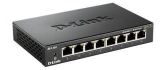
Twisted pair tester. Using this device, you can identify both a problem with the cable (break, short circuit) and incorrect crimping. There are devices with expanded functionality, they allow you to measure the speed in the LAN segment, the level of attenuation, etc.
As a rule, simple models with a minimum set of functions consist of two blocks: main and remote, the accepted designation in English is master and remote, respectively. Each block has LEDs numbered 1 to 8 and a ground wire G.
Testing is carried out as follows:
- The cable under test is connected to the main and remote modules.
- If the conductor is intact, the corresponding indicator lights up green; if there is a break, the LEDs do not light up; if the pairs are reversed or there is a short circuit, the color red is displayed. Some devices, in addition to light indication, can also provide tonal signals.
- Cross crimping tool, used when connecting sockets, patch panels, etc. It is not used for cable crimping; we have included it because it is included in standard kits for cutting twisted pair cables.
Actually, universal pliers will be sufficient for crimping, but it is more convenient to remove the insulation with a stripper, and use a tester to test the correctness of the wiring. On the Internet you can find a description of how to crimp connectors using a flat-head screwdriver.
This is indeed possible as a last resort when a crimper is not available. The quality of such a connection will be unreliable, so as soon as possible it is necessary to clamp the cable using pliers.
Tools and materials for connection
To connect you will need the following things:
- The IP video camera itself
- Power supply or switch supporting PoE standard (optional)
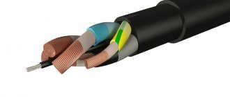
- A piece of two-core cable of the required length and cross-section (for power supply)
- LAN cable category 5 (twisted pair UTP Cat 5e)
- PoE splitter (optional)
- Power plug
- RJ-45 connectors
As well as a set of special tools.
There are 2 main types of network cables:
- direct – used to connect switches and modems to a computer. In this case, the connector pins are connected to each specific pin on the other connectors.
- null-hub – used to connect two computer devices using a network card. The circuit is as simple as possible and does not require the use of additional tool options, for example, a switch. In order to connect contacts in this case, a different method is used.
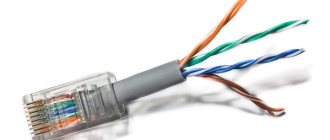
You can always buy a ready-made cable with RJ45, but in this case you definitely need to clarify with the sellers for what purposes you plan to use these cables. The choice of cable directly depends on this. For example, for IP cameras the UTP cable type is usually used - it consists of 8 cores, called twisted pair, which has a special connector.
The crimping procedure itself is as simple as possible, the main thing is that you must remember that the RJ45 connector must have the wires in the correct order.
Blue and brown, which are selected for the supply voltage, must be connected to the power connector. The brown type conductor is clamped into the terminal of the power plug and is marked “+”, and the blue type is clamped into the terminal and is marked “-”.
If we are talking about IP cameras with Wi-Fi, then only one power cable is used during installation. After this, he cuts the conductor to 1 centimeter, inserting it, without changing the sequence of colors, into the RJ45 connector, placing it with the contact group facing up.
Twisted pair today.
It is impossible to imagine a modern person who does not use a PC, much less a computer that does not have access to the Internet. All this has become firmly established in our lives. The concept of the Internet also includes various gadgets and smart TVs. In places where wired Internet is not possible, wireless communication prevails. But most users prefer the more reliable one - wired.
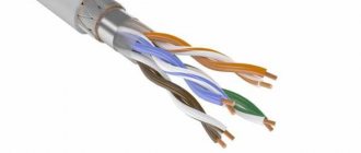
Despite the fact that many people connect WiFi routers, a computer outlet is still needed to connect to the network of the router itself. The wire intended for this purpose is called a twisted pair, which includes 2-4 pairs. This name is due to the fact that the pairs are twisted together to reduce the resulting interference. You can easily verify this by cutting such a wire.
In a home network, a wire with 8 cores is very often used, which makes it possible to take full advantage of the network. This method of connecting equipment to the Internet continues to be easier to set up and faster.
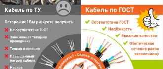
Types of cables for the Internet
If we talk about the types of cables used to build modern local computing systems, there are a huge variety of them
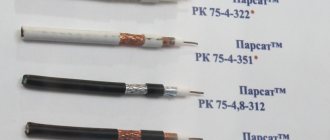
First of all, you should pay attention to the external structure, which prevents the influence of external factors. Conventionally, we can divide into the following types:. Outdoor cable
It has a reinforced braid that is resistant to moisture and ultraviolet radiation, its thickness reaches about 2-3 mm. It can also be equipped with a steel cable for ease of laying overhead communication lines. Traditionally black
Outdoor cable. It has a reinforced braid that is resistant to moisture and ultraviolet radiation, its thickness reaches about 2-3 mm. It can also be equipped with a steel cable for ease of laying overhead communication lines. Traditionally it is black.
Indoor cable. In this design, the cores are protected by a PVC sheath up to 1 mm thick, which loses its properties with prolonged exposure to water or sunlight. In expensive versions, it may have an additional reinforcing core in the form of a nylon thread.
Note! When crimping, many unskilled specialists neglect the presence of the reinforcing thread, not bringing it under the latch of the connector. This is fraught with cable breakage during sudden physical exertion. The second feature by which twisted pair cables for LAN are divided into subcategories is the presence of shielding
For this purpose, special marking symbols have been created: U - unshielded, unshielded, F - foil, the screen is made of foil, S - braided screening, an external screen in the form of a braided wire, TP - twisted pair, twisted pair (in fact, the main protection against electromagnetic interference), TQ - the presence of a dividing screen for each pair of pairs (simpler - four wires):
The second feature by which twisted pair cables for LAN are divided into subcategories is the presence of shielding. For this purpose, special marking symbols have been created: U - unshielded, unshielded, F - foil, the screen is made of foil, S - braided screening, an external screen in the form of a braided wire, TP - twisted pair, twisted pair (in fact, the main protection against electromagnetic interference), TQ - the presence of a dividing screen for each pair of pairs (simpler - four wires):
- U/UTP, all screens are missing;
- U/FTP, no external shielding, every two pairs are protected with foil;
- F/UTP, the overall shield is made of foil, no additional protection against EM interference is applied;
- S/UTP, overall shield made of braided wire, no internal shield;
- SF/UTP, combined external shielding, no shield for cores;
- F/FTP, both screens are made of foil;
- S/FTP, external – braided wire, internal – foil;
- SF/FTP, external - combined, internal - foil.
And finally, twisted pair cables are usually divided into categories, which directly affect the data transfer speed. It should be noted that categories from the first to the fourth are obviously outdated and are not capable of working in modern LANs; the rest are used for various tasks in designing data transmission channels:
- Category 5, 5e. Cables operating in the 100 MHz frequency band, the data transfer rate is 100 Mbit/second if 2 pairs are used and 1 Gbit/second if four pairs are used. The prefix “e” denotes the use of improved technologies, thereby reducing the diameter and cost. It should be noted that two-pair cables most often belong to category 5e.
- Category 6, 6A. Operating frequency band 200 MHz and 250 MHz, respectively. In the first case, it is a U/UTP cable, and the data transfer speed can reach 10 Gbit/second with a distance limit of 55 meters. In the second case, when there is a prefix “A”, there can be two types - F/UTP or U/FTP, then a speed of 10 Gbit/second is possible over a 100-meter segment.
- Category 7, 7A. Operating frequency band 600 MHz and 1 GHz, respectively. These cables are rare because they are approved by only one international standard; they also allow you to transfer information at a speed of 10 Gbit/second over long distances, and they come in two types: F/FTP or S/FTP.
Note! The final data transfer rate on the line can be significantly influenced by the quality of the secondary network elements. For example, if a 6A cable is used, but an RJ45 socket with a resistance that is not matched to this category is installed, the LAN will not work correctly, up to a complete lack of communication between devices