Adjustment and repair of relay REL, N
1 External inspection and external cleaning of the relay
Check for the presence of stamps on the screws closing the housing, RTU labels, and manufacturer's markings. Check the cutouts of the ABCD EZhZIK code in the selectivity plate with the selectivity code for this type of relay (Table 1). Figure 4 shows the ABC selectivity plate of the REL-1600 IR relay.
Rice. 1 Fig. 2 Fig. 3
Rice. 4 Fig. 5 Fig. 6 Fig. 7
Table 1 - Selectivity codes
| Relay type | Selectivity code | Relay type | Selectivity code |
| ABVIK | REL1M-10 | ABJZI | |
| REL1M-600 | ABZIK | REL1M-5/200 | ABVGE |
| REL1-400 | ABEJZ | REL2-2400 | AUGWHERE |
| REL1M-160 | ABESI | REL2M-1000 | AVGJ |
| REL1-6.8 | ABESQ |
Report to the SNS about any deviations from the established standards.
Clean the outside of the relay from dust and dirt with a cloth. Check that the contact blades are perpendicular to the relay base. The knives should protrude by 8mm. Straighten bent knives by adjusting or using pliers. Clean the contact blades with an eraser, wipe with alcohol and dry with a napkin.
Rice. 8
We don’t check for rust on the guides in the TC is empty?
2 Opening the relay
Remove the mastic from the screws with a screwdriver, and unscrew the four screws securing the casing. Remove the casing and clean the inside with a cloth. Wet and remove the old MOUTH label. Check for mechanical damage (chips, cracks) of the casing, the relay base, and the tightness of the casing to the base. Bases and casings that are cracked or chipped must be replaced.
Rice. 9 Fig.10 Fig. 11 Fig. 12
No photo of fit
Rice. 13
3 Internal inspection of the relay
When inspecting the relay internally, check the wires of the coil terminals: the installation wires should not have any damage to the insulating coating, should be flexible, laid neatly without tension and should not interfere with the movement of the armature and loads. Inspect the reels: the reels should not have damage to the outer insulation, cracks or chipped spools. Check the reels for labels indicating the wire brand, diameter, and number of turns. Check the quality of the solder by trying to pull it out with tweezers. Soldering must be even, smooth, without traces of rosin. In solder areas there should be no unsoldered or broken conductors.
No photo with tweezers securing wires
Rice. 14 Fig. 15 Fig. 16
4 Contact system repair
Inspect the contacts: the contact springs should be smooth, without deformation or signs of bending. Check the integrity of the insulating plastic gaskets of the contact groups, the absence of chips and cracks in these gaskets. Replace faulty gaskets with new ones. Clean the silver hardening of the movable and stationary springs with fine-grained sandpaper and polish with an elastic band. If there is significant burn, clean the contacts with a flat “velvet” file, followed by grinding and polishing.
Rice. 17 Fig. 18 Fig. 19 Fig. 20
The graphite contacts of the relay must not have cracks or chips. Using tweezers, check the fastening of the graphite contacts in the metal holders by attempting to displace them. The distance between the contact surface of the carbon contacts and the lower edges of the metal holders must be at least 1.5 mm (for new contacts) and at least 1.0 mm for used contacts. Check by applying a 1 or 1.5 mm probe to the contact.
Grind the front contacts by pulling fine-grained sandpaper glued to the plate. After cleaning all contacts, wipe them with alcohol and then with a clean cloth.
Check the reliability of the contact groups by grasping each contact group with tweezers and attempting to move it relative to the relay base.
Photo of the graphite probe
Rice. 21 Fig. 22 Fig. 23
Rice. 24 Fig. 25 Fig. 26
Replacement of defective contacts is carried out with the base removed without disassembling the entire contact system. Unscrew the screw of the required contact group, remove the defective contact and insert a new one, then secure the contact group with the screw. Move this to the block about replacing contacts and other components and develop
5 Repair and adjustment of the magnetic system
5.1. Anchor loosening
Remove the two screws securing the bracket to the yoke. Do not perform the following action during the lesson (the plate will already be bent):
Bend the corner of the armature plate slightly by adjusting it as shown in the figure. Remove one weight by turning it clockwise and lowering it. Remove the anchor with the shackle.
Rice. 27 Fig. 28 Fig. 29
Rice. 30 Fig. 31 Fig. 32
Clean cores, anchor, weights, yoke. Wrap a cloth around the screwdriver and wipe the yoke under the contacts. Wipe the yoke stop on which the anchor swings with a cloth soaked in alcohol.
Rice. 33
5.2. Preliminary adjustment of the contact pressure of the rear contacts
With the armature removed, install a 0.5 mm thick metal plate between all rear contacts and the rear contact stop (goose). Connect one lead of the light or sound indicator to the platinum. Consistently switching the second pin of the indicator to the rear contacts, measure the pressure of the rear contacts on the plate. To do this, apply the grammeter to the common contact until the light goes out or the indicator sounds turn off (until the rear contact and the plate open). The rate of pressing the rear contact onto the plate is 0.1-0.15 N (10-15 G). In case of deviation, bend the rear contact towards the general one (pressing less than 0.1 N) or away from the general one (pressing more than 0.15 N).
Remove the 0.5 mm plate.
5.3. Checking the adjustment of common contacts
Check the adjustment of the common contacts with the armature removed.
For full tees: pressing the common contact at which the common contact opens with the rear one should be 0-0.02 N (0-2 G). If I understood correctly of course.
For tees without rear contacts: there should be a gap of 1-2 mm between the common contact and the gooseneck (in the picture... adjustment of the right incomplete tee is required).
Adjust the general contact by bending the spring at the base.
+ photo of the fold of the common contact
5.4. Anchor installation
Check the Grover washers for cracks using a magnifying glass.
Reinstall the anchor and bracket. Press down on all common contacts from below with a screwdriver to bring the contacts to the same level. Insert the common contact tabs into the dielectric cutouts on the armature.
Place the plate on the bracket and screw the bracket to the yoke with Grover screws and washers. Do not tighten the screws. To ensure the standard armature play, insert a 0.2 mm feeler gauge between the bracket and the armature. Press the armature against the core and the bracket against the probe and armature. Tighten the screws securing the bracket. Check the gap between the armature and the bracket with feeler gauges (norm 0.1-0.25 mm): a 0.1 mm feeler gauge should go into the gap, but a 0.3 mm feeler gauge should not go through.
Maybe some additional photos of how to take the anchor with the bracket? during installation.
Insert the removed weight into the cutout on the anchor and rotate the anchor. Do not do what is written below in the lesson (leave the plate on the anchor slightly bent):
Straighten the plate on the anchor, securing the weight to the anchor.
After assembling the relay, check that the anchor and weights can move freely. The anchor and loads must move without snagging, both when the relay is in a horizontal position and when it deviates up to 5° from the horizontal position.
Well, are we going to check this or not???
Check and adjust the gaps between the weights and the limiter in the horizontal and vertical planes by bending the limiter. In Figure 2, the letter designations of sizes correspond to the following data:
G - 0.8-1.5 mm (with the armature released);
F - 0.2 - 0.5 mm (provide bending of the limiter);
E - 0.3 - 1.2 mm (provide bending of the limiter);
A - 0.5 - 1.5 mm (provide bending of the strips);
I - 0.1 - 0.25 mm (the gap between the anchor and the bracket is ensured by moving the bracket);
K - 0.1 - 0.25mm (provide bending of the bracket shelves)
* the gaps indicated in Fig. 2 should not be checked or adjusted, except for position I,
are specified structurally during the manufacture of the relay; use them as reference data.
* - TsShTs-37/142 dated 06/13/06. Deputy TsSH
Check and adjust play and clearances. They must comply with the established standards specified in Table 2. Check the gaps with feeler gauges, and check the gaps using a movement indicator with a division value of 0.01 mm.
Well, are we going to check this or not???
5.5. Checking armature backlash and clearances
Check the armature play along the prism (norm 0.1 - 0.5 mm) by installing probes in the gap between the armature and the bracket: a 0.1 mm probe should go into the gap, a 0.55 mm probe should not.
Gap between armature and core
To check the gap between the armature and the core, press the armature against the core with your hand. A 0.15 mm feeler gauge should pass under and above the diamagnetic plates in the gap.
5.6. Checking the armature stroke
Clamp a 0.35 mm feeler gauge under the diamagnetic armature stop. Make sure all front contacts are closed. If the contact is not closed, adjust it by bending the thrust spring of the front contact towards the common one.
Parameter name
Limit values, mm
1 The gap between the pole and the armature in the attracted position after covering them with a protective layer, not less than 0.15 2 The backlash of the armature along the yoke prism is 0.1-0.5 3 The armature stroke, measured under the stop, ensuring contact slippage, is not less than 0.356 Adjusting the contact system
The relay contacts must be adjusted so that the mechanical characteristics of the contact system after adjustment comply with the standards given in Table 3. When adjusting the contact system, it is allowed to slightly bend the contact and thrust springs.
Table 3 - Mechanical characteristics of the contact system
| No. | Parameter name | Limit values |
| 1 | Contact opening with the anchor pulled and released, not less than, mm | 1,3 |
| 2 | Contact pressure on contacts is not less than, N(Gs), frontline rear | 0,3 (30) |
| 0,15 (15) | ||
| 3 | Permissible deviation along the contact path (non-simultaneity), no more, mm | 0,2 |
6.1. When the armature is pulled all the way to the stop, the plates of all rear contacts must rest on the stop, and there must be a visible gap between all the plates of the front contacts and their thrust plates. When the armature is released, the plates of all front contacts should rest on the thrust plates, and there should be a visible gap between the rear contact plates and the stop.
Make the adjustment by bending the thrust springs of the front contacts and ??? But how can you ensure clearance at the rear if there is none?
6.2. Checking the simultaneous closure of contacts
Slowly pressing the armature against the core with your hand, check the simultaneous contact of the common and front contacts. If the contacts do not close simultaneously, check the admissibility of non-simultaneity (no more than 0.2 mm), to do this, determine at which probe placed under the armature the first contact closes and at which the last one. The difference should be no more than... ? mm.
In case of deviation from the norm, bend the thrust spring of the contact that closes first (towards the front contact) or last (towards the common contact).
I wonder if the simultaneous closing of the rear ones should be checked or not?
6.3. Place a 1.1 mm thick probe between the armature stop and the relay cores and press the armature. Check that there is a minimum uniform clearance between all common and rear contacts. If necessary, make adjustments by bending the arms of the anchor in the area of the weakened section.
???? I don’t like the bends of the anchor???
6.4. Possible deviation of one of the moving contacts from the general line of the moving contacts, eliminate the application of vertical force by adjusting the spring of the moving contact near the silver hardening.
6.5. Measuring and adjusting contact pressure
Adjust the contact pressure of the rear contacts to general. Place the relay in the horizontal operating position. Place a gram meter near the location where the rear contact hook is attached. It is more convenient to use a gramometer with a long beak. Press the spring until a gap forms between the common and rear contacts (or until the indicator lights up). The pressure must be at least 0.15 N (15 G). If the pressure is less than normal, bend the rear contact closer to the general adjustment.
+ photo rear adjustment
You can’t see the beak in the photo, where should I put it?
Measure the contact pressure of the front contacts. Press the anchor against the cores. Place the gramometer lever on the graphite contact cup and lift the spring up. Control the contact pressure at the moment of separation of the front contact from the general one. The rate of pressure on the front contacts is 0.3-0.32 N (30-32 G). Adjust the pressure by bending the front contact spring at the base.
6.6.
Place a 0.4 mm thick probe between the armature stop and the cores and press the armature against the cores. All normally open contacts must be closed. If the contacts do not close, bend the thrust plate of the front contact of this tee towards the common contact (in the figure ... line 1).
Place a 0.5 mm thick probe between the armature stop and the cores and press the armature against the cores. All front contacts must be open. Make the adjustment by bending the thrust spring of the desired tee towards the front contact (in the figure...line 2).
6.7. Checking and adjusting the intercontact distance
Press the armature against the core, check the gap between all rear and common contacts by trying to insert a 1.3 mm round feeler gauge into the gap. Release the armature, place the relay in the operating position, and similarly check the gap between all common and front contacts. If necessary, make adjustments by bending the thrust springs of the front contacts or... what if the rear contacts are less than normal?
7 Checking the parameters of the relay windings
Set the multimeter to measure resistance in the 200 or 2000 Ohm range. Measure the resistance of the winding pairs by connecting the device terminals to pins 1-4 and 2-3. at least I wrote the conclusions correctly
+ photo of multimeter settings COPY FROM OTHER TECHNIQUES
The resistance of the windings at a temperature of +20±5°C must correspond to the data specified in table 4.
Table 4 - Winding resistance
| Relay type | Number of turns of one winding | Resistance of one winding, Ohm |
| brand |
Relay.
The relays are adjusted on the stand for the current to operate and drop out.
| Contact position | Relay type | |||
| R-42B1 | R-42BZ, RD-8010 | |||
| Coil current, A | ||||
| current | voltage | current | voltage | |
| Closes………………….. | 0 | 0,05—0,055 | 0 | 0,075—0,085 |
| Opens………………… | 0 | 0,01—0,015 | 0 | 0,022—0,035 |
| They close……………. | 1,0 | 0,15—0,157 | 1,0 | 0,155—0,165 |
| Opens………………… | 1.3 | 0,023—0,026 | 1,3 | 0,052—0,065 |
Switching relay.
Relay adjustment parameters are given in table. 2. The relay is adjusted by screw 13, which changes the tension of the springs 12 and, if this is not enough, by changing the position of the plunger 8. Adjustment of the RD-3010 relay is also achieved by changing the air gap between the armature and the core of the current coil, tensioning the spring or changing (filing) the thickness of the non-magnetic soldering on the armature from the voltage coil side. The contact gap must be at least 2 mm, the gap must be 1 mm; contact pressing - 40 gs. The operation of the relay is additionally checked on a diesel locomotive when tested on a rheostat. Here, the current and response voltage are adjusted by changing the resistances in the relay coil circuit. As the resistance increases, the generator current at which the relay turns on and off increases, and as it decreases it decreases. If you increase the resistance in the voltage coil circuit, then the relay will turn on and off at lower generator currents, and, conversely, if you decrease the resistance, the relay will operate at high generator currents.
Boxing relay.
The parameters of the boxing relay must correspond to the following data: Operating current, A………………………………………………………………. 0.05 Return coefficient (ratio of the outgoing current to the retracting current), not less than ……………………………………………………….. 0.85 Gap between contacts, mm making... …………………………………………………………………….. 1.5-2 breaking ………………………………………… …………………………… 1.0—1.4 Contact failure, mm……………………………………………………….. 0.5— 0.8 The value of the relay switching current is changed by screw 12 (see Fig. 69), which regulates the tension of spring 14. When the screw is screwed in, the switching current increases, and when unscrewed, it decreases. The amount of contact rupture is adjusted by changing the position of the fixed contacts.
Setting up the pressure switch RDM-5 of the pumping station
The RDM-5 pressure switch is adjusted in a working system under pressure. To do this, we turn on the pumping station to the network and let the pump raise the pressure in the system, after which the relay will operate and the engine will turn off.
Next, we directly configure the pressure switch:
- Remove the relay cover and completely loosen the clamping nut of the smaller spring.
- We set the required minimum pressure (turn on the pump). To do this, rotate the clamping nut of the larger spring (clockwise - increase the pressure and vice versa). Then we open the tap and let the water drain, which reduces the pressure in the system. We watch when the pump turns on and, if the result is not satisfactory, we adjust further until we achieve the required result.
- We adjust the pump shutdown pressure (upper limit). By rotating the clamping nut of the smaller spring, we set the required value of the upper pressure. We proceed as follows. We turn on the pump and wait for the relay to operate. If the shutdown pressure is not satisfactory, drain the water, adjust the spring and repeat the process.
Thus, we configured the pressure switch.
How to determine that a refrigerator relay needs to be replaced
The starting protection relay makes it easier to start the compressor engine, the thermal relay protects the motor from overheating, and together with the temperature sensor regulates the cooling system. You can suspect that this part is faulty based on the following signs:
- the engine does not start;
- does not turn off, despite the fact that the temperature of the freezer has reached the desired level;
- The engine runs for a short time and then switches off.
To know for sure that the refrigerator start relay needs repair, you need to disconnect the terminals from it, then connect it directly to the engine. If it starts working, then the cause of the problem has been found. The second way is to connect a working device.
What type of relay can be repaired?
One of two types of relays can be installed in a car: collapsible and non-dismountable. If the car has the second type of relay, then you won’t always be able to fix it yourself.
A non-separable relay can only be repaired if the contact plates are burnt. If one of the windings has deteriorated or a short circuit has occurred in them, then it will no longer be possible to repair it - only replacing the part.
Important! In case of self-repair, when removing the relay, it is recommended to mark the terminals so as not to confuse them when installing the mechanism in place. It is also a good idea to clean and degrease the contacts on the relay and starter.
Troubleshooting
Given the small number of relay elements, you can sequentially test them for functionality. To do this you will need a flathead screwdriver and a multimeter.
No. 1 - problems with relay operation
From a design point of view, a relay with a coil is a device with normally open contacts, and a posistor version is a device with normally closed contacts. Although in both cases there are possible options when, at start, there will be no current supply to the starting winding or, conversely, its shutdown will not work.
If the compressor is operational, but does not turn on following a command sent from the refrigerator control unit, this indicates a lack of voltage on the stator starting winding.
The reason for this may be:
- electrical circuit break;
- contact strip problem;
- posistor overheating;
- the electrical protection system is triggered and does not return to its normal position.
If the refrigerator turns on for 5-20 seconds and then turns off, then most often this is a consequence of the relay’s protective mechanism triggering.
The reasons may be the following:
- the protective mechanism is working properly, but the operation occurs due to problems in the working winding of the motor;
- the protective mechanism is working, but the relay does not open the contacts in the starting winding circuit;
- The protective mechanism is faulty, false operation occurs when the temperature is slightly overheated.
Since there may be several reasons for the malfunction, it is necessary to carry out a complete diagnosis of the start-up protection relay of the refrigerator.
The cost of start-up protection relays for brands such as Atlant or Biryusa does not exceed 500 rubles. If you quickly purchase and install a new working device, the refrigerator will not even have time to defrost
No. 2 - faulty electrical circuit contacts
A faulty start-up relay can be detected using a multimeter.
To do this, you need to ring three sections of the electrical circuit:
- If there is a break in the area from the input to the output to the working winding, then it is necessary to check the location of the contact opening with the protective mechanism. It is possible that it worked and did not return to its original state or that the opening contacts were oxidized.
- If there is no contact in the area from the input to the output to the starting winding, then in addition to a banal break in the conductor, two options are possible: opening the circuit by a protective mechanism or lack of contact through the bar.
- A break in the straight (zero) section means mechanical damage to the chain - it is the easiest to find and fix.
If the relay operation is based on the use of an induction coil, then it is necessary to forcibly raise the bar - otherwise there will be no contact.
Using a multimeter, it is easy to detect faulty contacts by testing them through a resistance. It is important to take your time and check each section of the chain one by one.
No. 3 - incorrect operation of the posistor
To make sure that the posistor is working properly, you need to check it in a cold and heated state.
First of all, you need to wait until the posistor has cooled down (2-3 minutes in a non-working state is enough) and ring it with a multimeter. If there is no current or a high resistance is detected, the posistor is faulty and needs to be replaced.
If the device is working properly, then when checking it in a cold state, the multimeter should show the presence of slight resistance
To check the disconnection ability, you need to connect a consumer of electricity, for example, a hundred-watt incandescent lamp, to the posistor. To do this, you need an electrical plug with two terminals that are connected to the input of the device. The wires from the lamp are connected to the connectors leading to zero and the starting winding.
When the plug is plugged into the socket, the light will light up. Since the rating of the passing current in the experiment is significantly less than when starting the compressor, the posistor will heat up for a long time - for a hundred-watt lamp the response time will be 20-40 seconds.
If the light goes out after a while, then the device is working properly. If the consumer is not de-energized, this means that the posistor is not working. Repairing it at home is impossible, it is inexpensive, so you need to purchase an element with similar parameters.
No. 4 - problems with the contact strip
There are two types of contact strip problems:
- no current passes when the contacts are closed;
- The bar sticks and won't go down.
The first problem may arise due to oxidation of contacts. In this case, you need to clean them with sandpaper. Also, the reason may be the curvature of the position of the bar, then it is necessary to install it horizontally.
To clean the contacts and remove dirt or traces of oxidation, you can use fine sandpaper by placing it on a needle or thin flexible awl
A more difficult problem is the junction of the bar and the pin, which is affected by the magnetic field of the solenoid. The solution to the problem here is individual and depends on the type of malfunction.
Sticking of the strip is expressed in the fact that it does not come off along with the core. To do this, you need to clean the contacts to remove the adhesive and make them smooth.
No. 5 - abnormal operation of current protection
If, when ringing, a lack of contact is detected from the input to both windings, then most likely the break occurred in the protection zone.
In most cases, this is either a contact failure that opens the bimetallic plate, or damage in the area of the heating coil.
The bimetallic plate and its heating coil must not be bent, displaced or otherwise carried out with them that would cause a change in the configured operation mode
If the damage cannot be corrected otherwise, you will have to purchase a new relay.
Features of the retractor relay device
In order to independently repair any part in a car, you need to understand how it works. This will give you an idea of what elements are inside, how they work, and, accordingly, how to get to them for repair.
The solenoid relay is a capsule containing an electric magnet, a return spring and a rod. A magnet consists of two windings: a retracting core, and a winding that holds it in a certain position. It is their work that moves and fixes the core inside the mechanism.
As soon as the key is turned when starting the engine, the battery supplies electricity to the windings, which perform the retraction function. As a result, an electromagnetic field appears around the core, which sets it in motion. At the same time, the return spring is compressed, which will then return it to its original position. Together with these movements, the opposite end of the part is attached to the flywheel. Due to this, the gear connected to the bendix is connected to the flywheel and transmits movement to it.
As a result of all these manipulations, the engine starts. After which the mechanism turns off the electric current inside itself and returns all its parts to their original position. Only the core remains in its original position thanks to one of the windings.
Reference. There are relays with only one winding that has a pull-in function. But such parts are not common due to the fact that they consume a lot of electricity, and as a result, drain the battery faster.
Operating principle of the start relay
Despite the large number of patented products from various manufacturers, the operation schemes of refrigerators and the operating principles of starting relays are almost the same. Having understood the principle of their operation, you can independently find and fix the problem.
Device diagram and connection to the compressor
The relay circuitry has two inputs from the power supply and three outputs to the compressor. One input (conditionally zero) passes directly.
The other input (conditionally – phase) inside the device is split into two:
- the first passes directly to the working winding;
- the second passes through the disconnecting contacts to the starting winding.
If the relay does not have a seat, then when connecting to the compressor you must not make a mistake with the order of connecting the contacts. Methods common on the Internet for determining winding types by measuring resistance are not correct in general, since some motors have the same resistance of the starting and running windings.
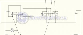
The electrical circuit of the start-up relay may have minor modifications depending on the manufacturer. The figure shows a diagram of the connection of this device in the Orsk refrigerator
Therefore, it is necessary to find documentation or disassemble the refrigerator compressor to understand the location of the feed-through contacts.
This can also be done if there are symbolic identifiers near the outputs:
- “S” – starting winding;
- “R” – working winding;
- “C” – general output.
The relays differ in the way they are mounted on the frame of the refrigerator or on the compressor. They also have their own current characteristics, so when replacing it is necessary to select a completely identical device, or better yet, the same model.
Closing contacts using an induction coil
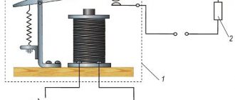
An electromagnetic starting relay works by closing a contact to pass current through the starting winding. The main operating element of the device is a solenoid coil connected in series with the main winding of the motor.
At the moment the compressor starts, with the rotor static, a large starting current passes through the solenoid. As a result, a magnetic field is created that moves the core (armature) with a conductive strip installed on it, which closes the contact of the starting winding. The rotor begins to accelerate.
As the rotor speed increases, the amount of current passing through the coil decreases, as a result of which the magnetic field voltage decreases. Under the action of a compensating spring or gravity, the core returns to its original position and the contact opens.
On the cover of the relay with the induction coil there is an “up” arrow, which indicates the correct position of the device in space. If it is placed differently, then the contacts will not open under the influence of gravity
The compressor motor continues to operate in the mode of maintaining rotor rotation, passing current through the working winding. The next time the relay will work only after the rotor stops.
Regulation of current supply with a posistor
Relays produced for modern refrigerators often use a posistor - a type of thermal resistor. For this device, there is a temperature range below which it passes current with little resistance, and above which the resistance increases sharply and the circuit opens.
In a starting relay, a posistor is integrated into the circuit leading to the starting winding. At room temperature, the resistance of this element is insignificant, so when the compressor starts operating, current flows unhindered.
Due to the presence of resistance, the posistor gradually heats up and when a certain temperature is reached, the circuit opens. It cools down only after the current supply to the compressor is stopped and starts skipping again when the engine is turned on again.
The posistor has the shape of a low cylinder, which is why professional electricians often call it a “tablet”
Adjusting the pressure in the pumping station
Setting up the pressure switch begins with checking the compressed air pressure in the hydraulic accumulator. In this case, the pumping station should be disconnected from the network and the accumulator tank should be empty. To do this, unscrew the side cap on the tank (see figure - red arrow) and use a regular car pump with a pressure gauge to check the pressure. It should be about 1.5 atm. If the measured value is less, the pressure must be raised by the pump to the required level. It should be noted that the air in the tank must always be under pressure, and when operating the pumping station it must be checked from time to time and pumped up if necessary, which will increase the service life of the accumulator membrane.
If, after adjusting the pressure in the accumulator, the pumping station does not operate normally, you need to start setting up the pressure switch itself. It should be remembered that the pump switch-off pressure (upper setting) should not exceed the pressure that the pump is capable of developing!