Often it is not enough to have only a pump for pumping out or replenishing water; it is also necessary to control it, that is, turn it on and off on time. Everything would be fine if you have such processes planned, but if not, then what should you do? Let's say you have a cellar where water comes in... Or the opposite situation. There is a tank that should always be full, ready for watering. During the day the water is warmed, and in the evening you water. So, one and the other must be constantly monitored, and this means all the time, worries, and your efforts. But in our age, such problems are already solved once or twice, that is, the process can be automated. As a result, the automation will do everything for you, pumping or pumping out water, and you will only have to monitor it very rarely. Check its functionality. Well, my article will be devoted to such a topic as the implementation of a scheme for pumping or pumping water according to level, then I will tell you about this in more detail and in detail.
More relay diagrams
Before the article was published, reader Alexey sent more diagrams, the description of which is given in the comments.
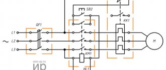
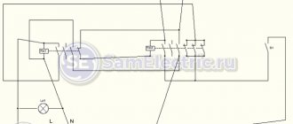
Scheme of automatic phase switching from the city electrical network and generator with foolproof protection:
Scheme of automatic phase switching from the city electrical network and generator with foolproof protection
Scheme of automatic phase switching from the city electrical network and generator with foolproof protection. I apologize for the editing, the main principle here is.
Scheme of automatic phase switching from the city electrical network and generator with foolproof protection
I discuss similar schemes in an article about connecting a generator to a home electrical network.
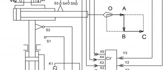
Here is another diagram, controlling three loads over two wires. The author explains in detail in the video how and what works:
Tips for selection and application
Before choosing a pressure regulator, you should understand how high the water supply is required, since the standard pressure is from 1.5 to 3 atm, and to supply water for every 5 m you need to add another 0.5 atm to this figure. Therefore, for the 2nd floor the minimum pressure will be from 2 to 3.5 atm.
You should also install a block on the pump that prevents damage from voltage surges. It also acts as a stabilizer for the current power supplied to the system. At critical values, the protection will turn off the power, and if the indicators are slightly different, but are not limiting, then it equalizes the voltage.
Before you start using the automation and pump, it is recommended to carefully configure all parameters, since they may be different for each well. Also, the settings depend on the presence of a hydraulic accumulator and its volume.
Download
If the topic interests you more deeply, I recommend that you read the literature listed on the page.
Here is one of the books listed there: • Lomonosov, V.Yu.; Polivanov, K.M.; Mikhailov, O.P. Electrical engineering. / Lomonosov, V.Yu.; Polivanov, K.M.; Mikhailov, O.P. Electrical engineering. One of the best books on the basics of electrical engineering. The presentation begins with the very basics: it explains what voltage, current and resistance are, provides instructions for calculating the simplest electrical circuits, and talks about the relationship and interdependence of electrical and magnetic phenomena. Explains what alternating current is and how an alternating current generator works. It describes what a capacitor is and what an inductor is, what their role is in alternating current circuits. It is explained what three-phase current is, how three-phase current generators are designed and how its transmission is organized. A separate chapter is devoted to semiconductor devices: it talks about semiconductor diodes, transistors and thyristors; on the use of semiconductor devices for rectifying alternating current and as semiconductor switches. The achievements of microelectronics are briefly described. The last third of the book is entirely devoted to electrical machines, units and equipment: chapter 10 deals with direct current machines (generators and motors); Chapter 11 is devoted to transformers; AC machines (single-phase and three-phase, synchronous and asynchronous) are described in detail in Chapter 12; switches, electromagnets and relays are described in Chapter 13; Chapter 14 deals with electrical diagramming. The last, chapter 15, is devoted to measurements in electrical engineering. This book is an excellent way to learn the basics of electrical engineering, to understand the fundamental principles of the operation of electrical machines and units., zip, 13.87 MB, downloaded: 2730 times./
Pump control: automatic
In this case, automation means a set of command relays, a power electrical part and various types of protection, the task of which is to protect the electric motor and the device itself from failure. In this article we will look at pump control systems. The most widely used are two main schemes for controlling pump operation: based on the level of the working medium (water) in the storage tank and based on the pressure in the pressure pipeline.
Pump control: level control
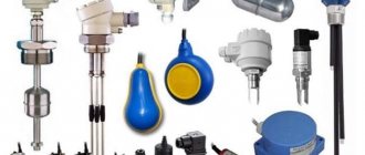
The first pump operation control scheme is used when the device is operating on a water tower or for filling a tank, from where water is supplied to the consumer by second lift pumps. Special level sensors (electrodes) are installed inside the containers, which, using a level control relay, monitor the lower (pump on) and upper (pump off when the tank is filled) levels. The use of float switches instead of electrodes in this circuit is less reliable, which is due to their short service life. An emergency drainage device must be provided when the tank overflows (overflow alarms are usually not used). This scheme is typical for large community wells, when one tank supplies water to an entire dacha settlement, village, village.
The main advantage achieved with this approach is stable operation. The hydraulics are constant: the nominal flow rate is supplied to a height determined by the depth of the well, the height of the tower, and additionally provides another 1–2 m for the spout. One cycle corresponds to the flow rate of the full volume of the tower, taking into account the flow rate of the current water intake. The possibility of short-term start-stops is eliminated, which extends the life of the equipment. It is enough to correctly select the electric pump for the required parameters, carry out commissioning in a qualified manner once, and stable operation of the system is ensured.
Pump control: pressure control
According to the second scheme, the pump is controlled by commands from a pressure switch installed on the pipeline. On the relay itself, two parameters are configured: the pressure to turn on the pump and the pressure at which it should turn off. This pump control scheme is typical for individual wells and is usually used in conjunction with membrane tanks designed to maintain the required excess pressure in the network, compensate for water hammer and low flow rates. It is extremely important to set the relay correctly in accordance with the characteristics of the device and the volume of the membrane tank. To prevent the pump from switching on too often, the set pressure limit should lie in the middle zone of the operating characteristic. The hysteresis of the values is selected in the range of 1.2–2.5 bar, taking into account data on the maximum permissible number of switchings in a certain period of time.
The pressure switches used in this scheme can be divided into household and industrial. The first, MDR relays from Condor, XMP (Telemecanique), etc., have powerful contact groups capable of withstanding current up to 16 A, but are not equipped with a setting scale indicating an adjustable pressure range. Such relays are adjusted using a pressure gauge. The advantages of this type of relay are their relative low cost and the possibility of use in power circuits (directly for pump control). The disadvantages are low adjustment accuracy and short operating life due to the influence of large starting currents. Industrial relays, FF4 from Condor and KPI (Danfoss), are distinguished by increased accuracy and reliability, but have low-current contacts and require switching through an external starter. The type of relay influences the choice of further electrical circuit and automation system.
When using household devices, it is enough to directly connect the pump through its contact groups to the network. The simplicity and low cost of this option attracts many buyers, but it does not provide any other advantages. Moreover, such cost savings entail additional costs during operation to replace a prematurely failed relay (contacts are burnt or oxidized). The user himself, having installed a new relay, is unlikely to be able to restore the previous settings and check the operating mode, which, in the worst case, can lead to device failure. The well-known saying “the miser pays twice” does not work here: if the pump breaks down, you will have to pay three times - for lifting the device, repairs and, the third time, for lowering it into the well and putting it into operation. To operate a pump with an industrial relay, intermediate devices are required (various options for control cabinets with or without additional protection devices).
Pump protection
As practice shows, the main reasons for the failure of a well pump are operation at high or low supply voltage in the electrical network, overload of the electric motor and operation in the “dry” running mode, i.e. without water. Any European manufacturer indicates in the technical documentation the requirements for the supply voltage (in Europe the standard is 1x230 or 3x400 V) and permissible deviations relative to the nominal value.
A radical way to ensure high-quality power supply to the pump is to use alternating voltage stabilizers of appropriate power, which is expensive. Most often, a voltage control relay is installed in the pump automation control system. This automation of the device turns off the pump in case of voltage drop and overvoltage, and can also monitor phase sequence and asymmetry (for three-phase motors). The presence of a turn-on time delay in the relay provides protection against frequent power surges in the network.
The electric motor is protected from overload using thermal current relays that turn it off when the set current value is reached. It is very important that the setting range of the current relay matches the rated current of the pump.
Protection of the pump from “dry” running can be carried out in two ways: directly - by the water level in the well using sensors (electrodes) or floats and indirectly - by the current value or the phase shift of the current and voltage of the electric motor using special relays. In some motors, MS 3 SQ pumps from Grundfos, this protection element is already built in as standard. The disadvantage of indirect protection is precisely its “secondary” nature: the relay operates only when the flow part and bearings are no longer supplied with water to lubricate and cool them. If the productivity of the device exceeds the flow rate of the well itself, a similar situation can occur several times a day, which negatively affects its service life. In this situation, it is strongly recommended to use an electrode level control relay, which allows you to turn off the pump before an emergency occurs.
Depending on the specific situation, various combinations and types of protective devices produced both by the pumping equipment manufacturers themselves and by other manufacturers can be used to control and protect a well pump. Let's take a look at the products offered on the market today.
Pump control devices
Conventionally, they can be divided into three groups: start-up protective devices assembled on the basis of printed circuit boards - QA/50B, QA/60C from Maniero, SK-701 from Wilo, etc.; control units based on relay technology – SK 277 (Wilo), “Hydromat” H110-H311 (“Hidrolans”), etc.; control systems based on microprocessor devices – SPCU3 (Control) MP204-S (Grundfos), SK-712 (Wilo) or similar.
Devices based on printed circuit boards are functionally and structurally complete products and require the connection of an external device - the pump itself, often through a starter and transmitting sensors (level, pressure switch, etc.). They are distinguished by a large set of controlled parameters and functions (thermal current protection, protection against voltage surges, control of “dry” running using electrodes and by electric motor load, etc.), which are not always used. Due to its completeness, it is almost impossible to change the operating logic of the device. Some devices do not have the ability to change trigger values for certain parameters. If the board fails, it must be replaced entirely, which is comparable to the cost of a new device.
The range of relay-based devices on the market is quite wide - from the simplest, SQSK (Grundfos), to control cabinets for several pumps, manufactured directly according to the requirements of a specific customer. The SQSK module is a regular starter in a plastic case. Its function is only to switch the pressure switch at a current of no more than 4 A. In practice, this unit no longer protects the pump itself, but the pressure switch. There is no status or settings signaling. Installation of an external circuit breaker is required.
The production control and protection unit N110 has a plastic waterproof case with dimensions of 310×230×130 mm, with a hinged, removable transparent cover, protection class IP65, sealed cable entries for connection. The module includes a contactor with an adjustable thermal current protection relay, a voltage monitoring device with a built-in digital voltmeter indicating the value of the supply voltage, operating mode signaling lamps, a circuit breaker for the internal control circuit, and a two-position On/Off switch.
As an option, the unit can be equipped with one or two level control relays RM4LG from Schneider Electric and terminals for connecting electrodes. The hardware “filling” of the device provides protection against all the main dangers for a well pump: when operating with an overload, current protection is triggered; when the supply voltage sags or surges, the control relay opens the control circuit and prevents the pump from turning on until the voltage returns to normal; When power is restored, the restart occurs automatically. A digital voltmeter shows the current voltage and signals the cause of the failure, which is convenient for the end user.
The advantages of devices of this type, as follows from comments and reviews, are their relative simplicity and reliability, the ability to quickly modernize and rework for non-standard applications; if a part fails, only the failed part is replaced.
Control and protection devices for well pumps based on microprocessor controllers are the most complex. They allow you to control pump operating parameters such as insulation resistance, motor temperature, phase asymmetry and phase sequence, protect the pump from high and low voltage, overload and dry running, and allow you to keep track of the pump operating time and the amount of electricity consumed. It is possible to communicate and control the operation of the pump through standard interfaces with a modem or computer. These are the most expensive devices, and it is recommended to use them with high-power and high-performance pumps, when the cost of possible pump repairs can far exceed the cost of the automation itself. Setting up, starting and commissioning the above devices without specialists is almost impossible.
When using frequency converters in control systems, it is necessary to take into account the minimum speed of the electric motor. This characteristic is indicated in the technical documentation for the pump and is usually 20–30% of the nominal value. If this requirement is not observed, there is a high probability that the pump motor thrust bearing will fail.
In addition to all of the above, special attention must be paid to the class of the selected control system for dust and moisture protection, depending on the installation location (see GOST R 51321.1-2000 “Complete low-voltage distribution and control devices”).
"AQUA-TERM" No. 3 (37) 2007
Read more about ways to manage these devices on our website.
Features of connecting a hydraulic accumulator to a well
The article mentioned a hydraulic accumulator (also known as a hydraulic tank, a membrane tank) more than once. In general, the purpose of this element of the water supply system is clear, but its role is so important that the issue requires a more detailed consideration. The principle of operation of the tank is as follows:
- water enters the membrane, the free gas is compressed, increasing the pressure on the stretched rubber;
- the tank is full - the relay turns off the pump;
- after opening the tap, the pressure drops, the relay turns on the pump again and brings the pressure indicator to the required value.
The operation of the membrane tank described above directly indicates that the main type of automation for a well pump with a hydraulic accumulator is a pressure control relay. The tandem of the membrane tank and relay significantly increases the service life of the pump, since it provides protection against water hammer when starting the pump, and also reduces the frequency of switching on - a small amount of water is supplied from the tank.
When connecting a hydraulic accumulator to a well, installing a check valve is of great importance. Its main function is to prevent water from going back into the well. The valve is mounted on the pump at its connection with the supply pipe. Mounting method: threaded. The thread is cut into the pump cover. The installation of the system has a strict sequence: first the valve is installed, then the hydraulic accumulator is connected.
Installing a check valve when connecting a hydraulic accumulator to a well plays a key role
Helpful advice! In conditions of unstable replenishment of the water layer, it is worth purchasing an automatic pump with a hydraulic accumulator with a water search function (automatic reboot) after the dry-running protection is activated.