How does a controller with a remote control for a chandelier work?
Briefly once again what we are talking about.
This remote switch, as a system, physically consists of two devices - a transmitter , that is, a control panel on which the user presses buttons), and a receiver , which is part of the controller. The receiver in the controller recognizes signals from the remote control and gives signals to turn on the relay of a particular channel. And through the relay contacts, power is supplied to the corresponding lighting group.
The whole system looks like this:
Chandelier remote control system - remote control and controller
We will not consider where the controller wires are connected in this article. This has been given a lot of attention in my other articles, links above.
Instructions for using and connecting the control unit are given on its body:
Instructions for controlling and connecting the LED chandelier controller
We open the case. To do this, you need to unscrew one screw, the rest - as usual in such devices, on latches:
We open the housing of the remote switch. Digital Remote Switch
In the photo, I specifically placed the remote control and controller next to each other so that the name could be seen.
Advantages
Smart LED control software allows you to control the color and brightness of the smart lamp at any time from a convenient position. Pros:
- suitable for chandeliers from different manufacturers;
- free to use;
- ease of use;
- fast access;
- simple installation procedure.
To understand whether you need an application to control smart LED chandeliers, you can imagine several situations. In order to turn off the light before going to bed, you need to get out of bed, go to the switch and go to bed in complete darkness. Smart technology allows you to turn off the lights with one touch of your smartphone screen.
LED chandelier controller circuit
Let me remind you that this remote radio-controlled switch (control unit) can be used not only in chandeliers, but also in other electronic devices. You can switch any voltage (within reasonable limits, with a little modification of the printed circuit board), and any currents (the current is limited by the relay current, but additional contactors can be installed).
The controller diagram is shown below:
Controller circuit for chandelier with control panel Sneha B-827
The diagram was taken by me from the site www.tokes.ru, thank you!
Having this diagram, you can safely take on repairing the controller, and the chances of success are quite high.
To examine the diagram in detail, I enlarged it and divided it into 6 conventional parts:
LED chandelier controller circuit broken down into parts for easy understanding
Let's look at each part separately.
Power supply and switching
This part of the circuit includes input and output circuits, and relay contacts through which the load is powered.
The relay coils are included in the 3rd part of the circuit.
Zero and phase come next.
Power supply 220 – 12 V
This part receives 220V voltage, zero and phase. Zero passes to the diode bridge through a choke, which to some extent eliminates high-frequency power supply noise, which can lead to failures. Capacitor C1 serves the same purpose.
The phase to the diode bridge comes through the quenching capacitor C2, which is shunted by resistor R1 for safe operation.
Each diode of the diode bridge is also shunted by a capacitor to minimize the high-frequency component of the supply voltage.
The output of the diode bridge is loaded onto filter capacitors C3 and C4, which serve to filter the low-frequency and high-frequency components of the bridge output voltage. The voltage is stabilized by a chain of series-connected 12V zener diode VD2 and limiting resistor R4.
As a result, at point A a DC voltage of 12.5-15V is generated in relation to the neutral wire (minus the diode bridge).
Key transistors
Key transistors are essentially amplifiers of a discrete signal that comes from the decoder. They are included according to the classical scheme.
Power circuit 12 - 5 V
Next, the 12V voltage is supplied to the +5V power stabilization circuit. The voltage at the input of this stabilizer is reduced and stabilized by a chain of resistor R6 and a 12V zener diode VD4 and supplied to the 78L05 integrated stabilizer. Further, the stabilized +5V voltage is additionally filtered by capacitors C5 and C6, since a special quality of constant voltage is required.
Radio module
The +5V supply voltage is supplied to power the radio module. The purpose of the radio module is to receive a signal from the control panel from the radio air and output it in such a form that a decoder can decode it.
Radio decoder
The decoder receives a signal at frequencies, each of which corresponds to a pre-designated signal. What is going on in the decoder is a company secret; the datasheet for the HS153SP-J chip could not be found.
If anyone has it, please share!
The “waste product” of the radio signal decoder is discrete voltages of the order of +5V, which open the key transistors.
Anyone who would be interested in aspects of the circuit’s operation that I didn’t mention, or who has something to complement or reproach me with, write in the comments!
Designs of modern chandeliers for remote control
In fact, using a remote control, you can control lamps of any design from a distance; it is enough to correctly take into account their electrical characteristics:
- rated and starting current;
- network voltage and frequency.
Even ancient exclusive chandeliers with a large number of incandescent lamps can be connected to the controller by building it into one of the places:
- instead of a wall switch;
- fixing a chandelier in the ceiling space;
- inside the protective case.
The first method exists, but is rarely used. According to the installation rules, the switch only breaks the phase; zero is not supplied to it. But the controller needs it to operate the power supply: additional wiring will be required.
Modern chandeliers are immediately created to accommodate the controller inside the housing and are equipped with:
- lamp sockets;
- garlands of LED strips;
- additional unique special effects lights.
Individual garlands and illuminators have their own blocks that use individual algorithms to generate unique lighting.
Internal boards of the chandelier
Mounting the lamp on the ceiling is done using one of the most common methods. To do this, an expanded base is created on the body with holes that allow the insertion of studs with decorative nuts that hold the total weight of the lamp.
Electronic components and components are placed inside the hollow base.
They are shown in the photograph and signed. These include:
- controller with an external antenna;
- power connection wires to phase and working zero;
- PE conductor terminal block;
- lamps;
- garlands of LED strips;
- scheme for the formation of special effects.
Since the controller is the main part, they removed the cover from it and showed an enlarged photo of the method of attaching it to the body using glue.
Reliable fixation of the tin base does not exclude the possibility of convenient removal of the electronic board located on the fiberglass plate. The board is shown in more detail.
Clear installation allows you to observe:
- channels A, B, C, connected to the relay modules with blue, yellow and white insulated wires;
- channel D, which performs the tasks of turning the unit on and off;
- a radio receiver made on a separate chip.
We turn the board over to the reverse side and examine it carefully.
The arrangement of the tracks clearly demonstrates the possibility of turning on all the lamps simultaneously to ensure maximum lighting effect or using them individually in different lighting modes. To do this, the red phase wire is soldered to the common part of the power supply of the channels, from which the remaining consumers are separated by switching on relay modules.
The double black wire of the working zero is soldered to the board traces and is used for:
- supplying zero potential to the power supply;
- wiring for lamps, garlands, lighting fixtures.
The controller we repair
Now the most interesting thing - I will describe the process of repairing the Kedsum K-PC803 controller , a photo of the appearance of which I already provided at the beginning of the article.
In the process of repairing this controller, like any transformerless electronics, you need to remember the danger - the circuit is always under mains voltage!
The circuit of this controller almost completely coincides with the circuit given above. The only difference is that this controller has not 2 channels, but 3. But the principle is absolutely the same. Let's take a little time to get acquainted with some of the internals and differences from the above diagram.
This is what a controller for controlling a 3-channel chandelier looks like from the inside:
Appearance of the controller circuit
A little closer:
Closer view of the controller circuit
Three relays (black, left) correspond to three control channels.
To the right of the top relay we see a row of black semicircular parts. These are three key transistors and a +5V stabilizer. Here's what it looks like from a different perspective:
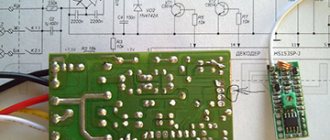
Details on the controller PCB
In this photo you can distinguish transistors Q1, Q2, Q3 - key ones for turning on the relay (type - C9013), a + 5V stabilizer for powering the radio frequency part - L78L05, and a radio signal decoder chip HS153SP-J.
Reverse side of the circuit (soldering side). I signed the conclusions in the photo to make it easier to carry out reconnaissance:
Controller printed circuit board. View from the soldering side
Controller Implementation
Schematic diagram
Work algorithm
The RF 315 MHz receiver hangs on the zero external interrupt and receives commands from the radio remote control. To work with the radio module, the RCSwitch library is used. A short (single) press of one of the remote control/switch keys is processed, which turns on/off a section of the chandelier, and a long (over 2 sec) press, which turns on/off all sections of the chandelier entirely. I wanted to use a long press to dim a specific section, but decided to abandon this function as unnecessary. The light turns on with increasing power over 5 seconds. It turns off the same way. Power is regulated by powerful MOSFET transistors using a hardware PWM microcontroller. When all channels of the chandelier are turned off, the mains voltage is removed from the powerful power supply side using a triac to reduce power consumption in standby mode. When the temperature is reached on one of the radiators, measured using DS18B20 sensors, the power on the corresponding LED section is reduced by 50% and the overheating LED lights up. The OneWire library is used to work with sensors
Full sketch of a chandelier control controller
The process of repairing the chandelier control unit
The problem with the faulty controller was that more than one relay would not turn on. And sometimes one relay might not turn on. That is, if one more relay can be turned on, then the second and especially the third are no longer turned on.
To repair, you first need to make sure that the remote control is working (the batteries are normal, and when you press any button on the remote control, the indicator lights up), and supply power to the controller:
We connect the controller to carry out measurements and checks during the repair process
I connected the power through the Vago terminals, it is very convenient. I inserted both wires N (black) into the terminal block, although either one is enough. The fact is that I do not connect the load, and wire N, if it dangles, can short-circuit to the output phase wires. The presence of output voltages can be checked by connecting 3 load lamps. But you can do it simpler - check the presence/absence of phase at the outputs with a phase indicator.
For convenience, I recommend that you connect our device not through a Vago, but through a two-pole circuit breaker, so as not to plug it into a socket; it’s more convenient to turn it on/off. Denomination – the lower the better.
It’s even better, for safety, to power the device through a 220/220 V transformer, for galvanic isolation from the network. Then the risk of electric shock will be significantly reduced.
First of all, we check the supply voltage. We measure with a conventional multimeter, switched to constant voltage mode, on the electrolytic capacitor of filter C3. In relation to the common wire (minus the diode bridge and capacitors C3, C4, as is more convenient).
The voltage when the relays are turned off (almost no load, idle) on the filter capacitor is 11.2V; when any of the relays is turned on, it drops to 6V. At this voltage, even if the decoder gives a signal to open the transistor and it opens, the relay will still not turn on.
Naturally, suspicion immediately fell on the part of the electrical circuit responsible for power supply. Namely, to the limiting capacitor C2 in front of the diode bridge.
It says 155J. This means 15x10^5 picoFarads. And since there are a million picoFarads in 1 microFarad, this means that the capacitance of the capacitor is 1.5 μF. The voltage is clear, 250V.
If its capacitance has dropped, then it greatly limits the current of the diode bridge, and under load the voltage at the bridge output (and at the input, in the first place) drops significantly.
By the way, note that in a controller with 2 channels, the capacitance of this capacitor is less - 1 µF. After all, the power supply power required is less than for three relays.
Another possible culprit for the drawdown is the electrolytic capacitor at the output of the diode bridge 470 uF 25V.
We change the 1.5 µF capacitor.
The price of this in radio goods or on the radio market is about 15 rubles.
Now we measure the voltage at the output of the diode bridge in four operating modes:
- idle: 12.9V,
- switching on one relay: 12.2V,
- switching on two relays: 11.7V,
- switching on three relays: 10.5V.
Everything works fine!
It should be noted that low supply voltage (12...15V) can be not only due to a malfunction of the power circuit, but also due to abnormally high current consumption in the load. In particular, these could be zener diodes, a +5V stabilizer, or a load at the output of the +5V stabilizer.
Other malfunctions of chandelier controllers are below:
Problems
- The RF 315 MHz receiver refused to operate stably at a supply voltage of 3.3V. I had to replace the power supply with 5V.
- MOSFET IRF540 transistors did not open completely when voltage was applied to the gate from the discrete output of the Arduino (~3V). I had to install an additional transistor BC547, which supplies 14V to the gate of the field switch, and the PWM signal had to be inverted (0 is 255, 255 is 0)
- A powerful 10A power supply, when the network is supplied to it by a triac, turns on with a delay of ~ 1-2 seconds. It was not possible to overcome the delay in the light, except by not turning it off completely.
- The IRF540 field devices and the BT139 triac have a non-insulated case, so they cannot be placed on a common radiator, and for the semistor we also had to come up with cardboard insulation, since there is a phase on the case
Typical malfunctions of the chandelier control unit (controller)
It should be remembered that most often in any electronic devices problems arise with connection or power supply.
In the controller circuit, repairs can be made according to the following points:
- Checking the presence of 220V input voltage.
- Checking the open circuit voltage 12...15V at the output of the diode bridge. If this voltage is not present, check the limiting capacitor, diode bridge, filter capacitors, zener diode. To eliminate the influence of subsequent parts of the circuit, disconnect the load of the power supply circuit by cutting the track on the board.
- Check the voltage at the input and output of the +5V stabilizer.
- Check the operation of the decoder. If there are signals from the remote control, voltage will appear at the outputs of the decoder and the corresponding bases of the transistors.
- Check key transistors. When they open, the relays should turn on.
- When the relay is turned on, the phase should appear at the corresponding controller outputs.
If not repaired
If the repair has reached a dead end, and there are no resources (psychological, material and time) to continue it, then you can simply buy a controller.
I believe that these three controllers have the same hardware, with the exception of the number of relays with transistors, and the power of the internal power circuit.
Of course, it’s not possible to describe all the intricacies of circuit design and repair of radio-controlled chandelier controllers here, so ask questions in the comments, and we’ll figure it out together.
Chandelier controller option:
All controllers have approximately the same circuit, only the brands are different. For example. Photo of the chandelier control unit sent by a reader:
Chandelier controller Wireless Switch Y-B2E for 2 outputs
Faulty CADJA B-2 chandelier controller needs repair. Photo sent by reader
Update: Simplified chandelier controller diagram
Reader Vadim sent a slightly different controller circuit, see comments dated December 24, 2022 and later.
Diagram of a control unit for an LED chandelier controlled from a radio remote control
There is a small “inaccuracy” in the diagram. Instead of a jumper after L1 there should be a filter capacitor!
I will briefly consider the operation and differences of this scheme from the previously published one.
Up to the point of the first stage of the +14.3 V power supply circuit, the circuit is practically the same. At this point, 4 voltages are indicated, which correspond to the number of switched on relays: 0/1/2/3. Instead of key transistors, the ULN2001 microcircuit is used, which performs the same function of key cascades.
Next, the voltage is applied to a 470 Ohm resistor, and using a zener diode VD7 is converted to a voltage of about 5 V.
Next, everything, as in the first version of the circuit, is a radio module and a signal decoder.
How the repair of the chandelier control unit ended in this diagram - read in the comments after December 24, 2022.
Installation and repair of a radio-controlled chandelier
Here I will talk about the design and malfunctions of radio-controlled chandeliers with halogen and LED light sources.
Despite all their diversity, almost all chandeliers with a control panel have a modular design and are assembled from the same type of electronic components.
Here are the main ones:
Radio-controlled relay and control panel;
Lamp with halogen lamps.
Depending on the design, chandeliers can be either pure LED or combined with halogen lamps. Thanks to the radio-controlled relay, you can turn on either all the lamps, or only the LED or halogen part.
Where to buy parts and ready-made blocks for repairing a chandelier with a remote control?
Hereinafter I will refer to the well-known online store AliExpress. It is there that you can find all the necessary spare parts and units, which will be discussed further. My choice is due to the fact that there is a large selection and low prices.
In radio markets, as well as in electrical goods stores, similar products are more expensive - their prices are simply “inflated”, although the quality is the same. Therefore, for those who know how to buy on the Internet, I advise you to pay attention to this. The only disadvantage of such purchases is the rather long delivery (1-2 months), although this largely depends on the seller. I have already talked about how to search and order goods on Aliexpress here.