Electrician in the house
Encyclopedia about electricity from A to Z
Masters catalog
Find the best master or company in your city
The most common type of sockets with remote control
The plug connector for connecting various devices to the electrical network is known to everyone, but it is not always convenient to use. Therefore, let's consider such an interesting thing as sockets controlled by remote control. We'll tell you how they differ from conventional connectors, and when you should choose them. Additionally, we recommend the video at the link, which tells in detail about these devices:
- What are remote sockets for?
- What is a socket with a remote control?
- How to control sockets with a remote control Mechanical control
- Via wired channel
- Acoustic control
- IR channel
- Radio channel
- GSM channel
- On ready-made modules
What are remote sockets for?
Today's complex household appliances almost always have their own remote control systems, but the simplest appliances are not equipped with them. In addition, standard remote controls are not always convenient. An outlet that can be turned on and off from a distance is useful in the following situations.
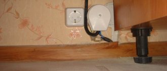
- If access to the outlet installation site is difficult, this is very common today. For example, they installed a cabinet that covers it, but there is no other one nearby. Of course, you can install an additional connector, but this requires repairing the wall decoration after installing the wiring. Also, in rented premises, any work to change communications must almost always be coordinated with the owner.
It’s difficult to get to such an outlet
In addition, a hidden outlet is sometimes a big plus - if it is visible, it may not fit into the interior. For example, in historical buildings (or you want your house to look old), where the atmosphere of an era not familiar with electricity is recreated.
Therefore, it is easier to hide an outlet behind a cassone, chest of drawers, desk or wardrobe and control it remotely than to put an object of modern design on display in an apartment built before Columbus discovered America (as in the photo below).
In such a room it is better to hide sockets
Even such an antique porcelain plug connector at first glance is only from the 50s-80s of the last century
- For connecting simple heating devices - air convectors, oil radiators. If the house gets too hot, you can simply turn off the heating in one motion, without getting up from the couch.
Electric convectors are conveniently connected to sockets with a remote control
- If you use communication channels (more on this below) that can operate over a long distance, it is possible to turn on a volumetric water heater and other devices at a great distance from the house. We leave work, turn on the boiler and heating - a warm house and a shower are ready upon arrival.
If you turn on a volumetric water heater with a remote-controlled socket, then when you come home from work you can immediately take a hot bath
- For particularly suspicious people, remote control (also with a large range) is a huge plus - alarms about whether the iron or kettle has been turned off can be eliminated by remotely turning off the socket.
The remote control will save you from such troubles
In addition, remote control increases the service life of both the devices themselves and the sockets. Simply pulling the plug loosens the sockets and burns the contacts, but the electronic control (especially if the remote socket contains triacs rather than relays) is almost eternal.
The remote control will get rid of burnt contacts
What are the best Wi-Fi outlets?
Which Wi-Fi sockets are better?
Not all smart plugs are as good as they claim. That's why we spent a lot of time testing to find the best smart plugs to buy.
After testing dozens of available smart plugs, we've found that the best overall is the $24 Perenio Power Link smart plug. It is compact, convenient and functional.
The best budget smart plug is the Tapo P100 from TP-Link. A single outlet costs just $13, and other smart home products have generally proven to be reliable.
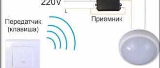
What is a socket with a remote control?
This is how a remote controlled socket works
If a regular socket includes only a housing, contacts (usually three or four, depending on whether single-phase or three-phase connection of devices is provided, and whether there is a grounding or neutral wire), as well as additional parts for fasteners and, possibly, decorative elements, then The remote-controlled socket has two additional blocks:
- switching unit for supplying current to the connectors;
- receiver block - receives signals from the remote control and commands switching.
Also, the third block can be considered the control panel itself, although its role can be played by other devices, for example a smartphone or even the person himself, if we consider sockets with sound control.
TOP 5: Best smart plugs of 2022
| № | Name | Description | Price |
| 1. | Perenio Power Link | The best Wi-Fi outlet | 24$ |
| 2. | Xiaomi Smart Plug | Popular smart plug from Xiaomi | 19$ |
| 3. | HIPER IoT P01 | Smart socket for working with Alice | 18$ |
| 4. | TP-LINK Tapo P100 | Reliable Wi-Fi + Bluetooth socket | 13$ |
| 5. | GEOZON GSH-SSP01 | High Power Smart Plug | 17$ |
How to control sockets with remote control
There are several ways to communicate between the receiver and the remote control. We list them, describing their advantages and disadvantages.
Mechanical control
Something like “Little Red Riding Hood, pull the string and the door will open.” This can even include simply pulling the plug by the cord (I don’t recommend it, it’s dangerous).
Because of its primitiveness, we won’t even consider it. Although it should be noted that the first TV remote controls used exactly this method.
An example of a mechanical remote control - a cable for releasing the camera shutter
Via wired channel
One of the most reliable channels, absolutely protected from interference. Many short-range missiles and torpedoes are controlled by wire, but for a socket this is not remote control (we get additional wires to control the wires). Therefore, we don’t consider it either.
Wired remote control (also for camera)
Acoustic control
The method is not the best, since it is very afraid of interference, and speech and music can be a source of false positives. Even if you filter the sound, there may still be errors (on smartphones, the “Ok Google” command sometimes turns on by itself during a conversation).
Interesting. The first TV remotes also used this principle. The Zenit Commander console had a set of metal plates that, when a key was pressed (like a piano), emitted infrasound of a certain frequency. The receiver responded to it. The remote control itself lasted forever, no batteries.
TV remote control with infrasound control, works forever and without batteries
We will not develop this topic in detail either, so as not to move away from outlets, but perhaps it is worth addressing it seriously for two reasons.
- To control staircase lighting, this is the best option, since acoustic control saves energy. That is, even if the sensor does not respond to the sound of a door opening and footsteps, you can turn on the lighting with your voice or clap your hands.
- Why we turned in more detail to the design of this channel - the fact is that staircase lighting is general communications, and their operation is carried out by the housing and communal services or another similar structure. An ordinary tenant does not have the right to make changes. But if it’s dark, then no one bothers you to install an adapter with a remote control into the socket, which responds to sounds, and connect an additional lamp to it. In this case, you do not touch the wiring.
IR channel
The outlet is controlled using invisible infrared radiation. Most remote control systems for household appliances (TVs, stereo systems, air conditioners) operate on this principle. The IR control system is simple and has a rich element base.
In some cases, when assembling such an outlet yourself, you can not even make a remote control, but adapt a purchased universal one or a remote control from other electrical equipment.
But there are also disadvantages:
- Control is possible only with direct visibility (in some cases it is possible to trigger the sensor by radiation reflected from the walls). It is impossible to turn on the socket at a great distance or from the next room with the doors closed.
- False alarms are possible from light sources whose spectrum also includes the IR region (for example, a socket with an infrared remote control can be triggered by a flash of lightning) or from a command from a third-party remote control.
IR controlled sockets
Radio channel
One of the oldest (not counting wired) methods of remote control. Allows you to turn on the device (with sufficient sensitivity of the receiver and transmitter power) not only at a distance, but also from several kilometers away.
However, the range is still limited. The simplest circuits of such devices can be sensitive to interference, so it is advisable to implement a signal encryption system.
Radio controlled socket
Note that Wi-Fi and Bluetooth receivers and transmitters are often used. This approach allows you to control the outlet not only using a separate remote control, but also to issue commands using a mobile phone or tablet.
If you use Wi-Fi, the remote control can be a smartphone
GSM channel
In principle, it is the same as a radio channel, but this control is more convenient, since you can control the outlet from anywhere in the world where there is cellular network coverage. To simplify assembly, either special modules or cheap (old) mobile phones are used as receivers.
For example, while in another city, using such an outlet you can turn on the heating in the house or the aerator for the aquarium. There is only one drawback - you need to pay the telecom operator for using the SIM card.
GSM controlled socket
Principles for setting up different types of sockets
Mechanical and digital timers for 220 V have different principles for entering program data. In the first case, a ready-made time scale is used (as in a time relay), which serves as a template for configuration. Each of the blue segment keys is responsible for a period of 15 minutes. If any of the segments is pressed, the timer organizes the supply of electricity to the device. The TM50 scale looks like this:
As you can see, some of the keys are pressed (the period between 16-00 and 18-00, and also below - starting from 2-00). In addition, in the central part there is a rotating disk (the direction is indicated by an arc arrow) with a current time indicator (in the example, the triangle is set to 13-00).
You can learn more about how to set up such a timer in the following video:
The digital timer is set using the display and softkeys:
- TIMER – key for entering data and confirming it,
- WEEK – button to select the required day of the week. The screen displays the selection in English (MO, TU, WE, etc.),
- HOUR, MINUTE – enter time,
- CLOCK – used in combination with TIMER to change the time format from 12 to 24 hour,
- ON/AUTO/OFF – key for selecting manual or automatic operating mode,
- RANDOM – selection of the floating switching function (periodic switching is carried out within a given period of time with an interval of up to 30 minutes).
A visual overview of such a timer is in the following video:
Several diagrams for self-assembly
Now let's look at several diagrams for assembling a socket with a remote control with your own hands, which were found on the network. Let’s not hide that these circuits are generally suitable for many other devices for controlling electrical equipment at a distance, so we will try to select the most interesting ones that require different levels of skill.
Moreover, we chose the first two schemes with radio control, since sockets with IR control, despite the fact that they are much cheaper, will not save you from the problem of a “burning iron” - you left the house and forgot whether you turned off the electrical appliance.
On ready-made modules
The easiest way to assemble a remote-controlled socket is in just a couple of hours using a set of ready-made modules that can be easily purchased on the Internet. The device has pretty good characteristics - switched load up to 2 kW and 10A, range up to 50 meters. Although we will say that the cost is low (you will have to pay about 2 thousand rubles for all the blocks), you can assemble it yourself for less.
We will need:
- receiver module with switching device MP912;
- The power supply for it (you can assemble it yourself, but it’s better to buy it in pairs, especially since there’s a discount on the set) WP1245;
- MP910 remote control.
The price for everything, if you purchase a receiver and power supply, is approximately the same as for ready-made sockets with radio remote control, but, nevertheless, it will be done with your own hands.
Assembly does not require any special knowledge of radio engineering, the main thing is to be able to read circuit diagrams and hold a soldering iron and wire cutters in your hands. Here is a diagram of connecting the receiver and power supply.
Receiver connection diagram
The socket can be assembled in several versions:
- like a regular overhead (you will have to find additional volume in the case, for example, by removing the switch in a socket with a switch);
- as built into the wall (in this case, additional volume for electronics can be found in the volume of the wall, not forgetting about cooling the elements);
- as an adapter for a socket;
- like an extension cord or splitter.
Below are instructions on how to assemble a remote socket. It's just a few steps:
- On the receiver board, with a drop of solder, we bridge two “patches” to select the signal encoding option (as in the photo below, shown by the red circle).
Selecting encoding in the receiver and transmitter
- Having disassembled the transmitter, we close the spots on its board in the same way, then assemble the case again.
- We connect the receiver to the power supply.
- We connect the power supply and the receiver relay to a 220 volt network (if the socket is built-in, then directly or through a switch, if it is made as an adapter or extension cord, then to a cord or plug).
- We test the design - when you press the transmitter buttons, clicks of the receiver relay should be heard.
- We install the receiver with the power supply into the case.
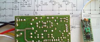
Scheme without using ready-made modules
The following circuit is assembled from scratch, and is intended for more experienced radio amateurs. A huge plus is that it works at a distance of up to five kilometers.
If you live close to your place of work (for example, in a small village), then having a remote control with you, you can turn on and off any device in the house. In addition, by making small changes, you can increase the number of channels and control not just one outlet, but several.
Note that it is also interesting because it is done without ready-made modules (unless we consider microcircuits as such), and this is of interest to many craftsmen. The cost of all components is about a thousand rubles. However, all the parts are very common and can be removed from old devices.
To make it easier to assemble devices, we provide not only circuit diagrams, but also drawings of printed circuit boards.
Schematic and printed circuit board of the receiver with names and ratings of parts.
Attention. The printed circuit board design is designed for small-sized parts - resistors and capacitors (except for microcircuits, of course). Therefore, if some element does not fit, it can be adjusted; it is not difficult, but the size may increase
The receiver circuit works as follows:
- A receiving circuit tuned to the operating frequency (27.12 MHz is the permitted range for such devices) is assembled on coil L1 and capacitors C1 and C2. Diode VD 1 suppresses excess signal if the transmitter is nearby.
- A high-frequency amplifier is assembled on transistor VT 1. A field-effect transistor was chosen due to its high sensitivity.
- The DA 1 chip contains a local oscillator, the signal of which is mixed with the signal of the high-frequency amplifier. For stable operation of the local oscillator, its frequency of 26.655 MHz is set by the quartz resonator Q 1.
- The intermediate frequency signal of 465 kHz is filtered through resonator Q 2. Installing a resonator instead of a conventional LC filter provides high selectivity of the receiver.
- Then the intermediate frequency signal is fed to an amplifier, which is assembled on part of the DA 2 microcircuit. The microcircuit also includes an automatic signal level controller, a detector and a low frequency amplifier (LF). To adjust the signal at the ULF input, a trim resistor is installed between pins 9 and 8.
- From the output of the low-frequency amplifier, a signal is sent to an amplifier assembled on transistor VT 2 and a reflex cascade on coil L2 and capacitor C 19.
- The reflex cascade is set to a frequency of 1.25 kHz. The appearance of a low frequency of exactly this value leads to resonance and a constant voltage appears at the cathode of the diode VD 2. It opens the transistor VT 2, the collector circuit of which includes a relay XC, which controls the supply of current to the socket connectors.
Here are the winding data of the coils and the markings of elements that are not indicated in the diagram:
- Coil L 1 is wound on a ferrite rod with a diameter of 2.8 millimeters and a length of 1.2 centimeters. Winding wire with a cross-section of 0.31 millimeters. The number of turns is 14. The coil is wound in such a way that it can be moved along the core for adjustment.
- The L 2 coil is wound on a 400NN ferrite ring with dimensions K7-4-2. It contains 350 turns of wire with a cross section of 0.06 millimeters.
- Piezoceramic filter FGLP 061-02, although any other can be used, the main thing is that the frequency matches.
- Relay type RES-55, but you can also use RES-43 or 44 or any other. If it is necessary to switch a load of more than 0.25 amperes, then we additionally install a contactor, the winding of which will be controlled by the relay, and it, in turn, will control the load.
If a large load is planned, then an additional contactor must be installed
Interesting to know. The diagram shows a battery as a power source. For a socket receiver, this approach is nonsense, so it is better to use a power supply from the network (there are many circuits, including a transformerless one, as in the image below). However, today it is much easier and cheaper to buy a ready-made power supply (for example, the same as for the previous device) or use the filling of a damaged (frayed cable) charging unit for electronic devices.
The simplest transformerless power supply
Next we'll look at the transmitter. Here is his diagram.
Remote control transmitter diagram and board drawing
It is a little simpler than the receiver, like all transmitters, designed to work with one receiver and at one frequency.
It works as follows:
- Transistor VT 1 operates in a carrier frequency generator - it is stabilized by a quartz resonator Q 1 at 27.12 MHz. The signal is isolated on inductor L 1, after which it is supplied to the power amplifier through capacitor C8 (to eliminate the influence of subsequent circuits and additional filtering of the signal).
- A high-frequency amplifier (UHF) is assembled on transistor VT 2, which raises the generator signal to the required supply level to the antenna.
- To match with the antenna and remove unwanted harmonics, a multi-stage adjustable filter is used on coils L 4, L 5, L 6 and capacitors C 13, C 14, C 15. After this, a simple whip antenna is connected through a capacitor C 17. For maximum sensitivity of the system, its dyne should be more than half a meter, that is, all telescopic options from any radio receivers are suitable.
- Transistor VT 3, whose emitter-collector junction is included in the collector circuit VT 2, on which the UHF is assembled, is intended for amplitude modulation. The more it is open, the higher the carrier frequency signal level.
- To trigger the receiver relay, it is necessary that after detecting a radio signal, a low frequency signal of 1.25 kHz is generated; it is generated by a multivibrator based on the “or - not” logic elements D1.1, D1.2 of the simplest digital microcircuit of the LE 5 type. The frequency is set by the resistor values. R1 and R2, as well as capacitor C3.
- The signal is supplied to the modulator through chain D1.3, D1.4, which is controlled by switch S 1. If it is open, then the radio signal is modulated with the required frequency and the receiver relay is turned on, the socket powers the consumer, if it is closed, then there is no power.
Now we present the names and values of elements that are not indicated on the circuit diagram, as well as possible replacements with analogues:
- Quartz resonator Q 1 - any, designed for a frequency of 27.12 MHz.
- Coils L 1, L 2, L 3 are wound using MLT 0.5 resistors with a nominal value of at least 100 kOhm as a core. They contain 40 turns of wire, with a cross-section of 0.16 millimeters.
- Coil L 4 and L 5 without core. Their diameter is 7 millimeters, length ten. The first contains 15 turns of wire with a cross-section of 0.61 millimeters, the second 20 turns with a cross-section of 0.56.
- Coil L 6 is wound in the same way as on the input circuit of the receiver, on a ferrite rod with a diameter of 2.8 millimeters and a length of 12. It contains 18 turns of wire with a cross-section of 0.2 millimeters and must move freely along the core.
- The 176-series microcircuit can be replaced with exactly the same (LA7) 561-series or even 564-series (but in the latter case you will need to slightly change the board layout). Moreover, if the marking does not have the letter “K” in front of the series number, it will be even better, due to the fact that the batch from which this microcircuit is from is not for general use, but special - for military products, and therefore more reliable.
- The KT 608 transistor can have any letter index (this also applies to other transistors),
- Analogs applicable in our circuit to replace the KT 608 transistor are KT 606 and KT 907.
- The VT 3 transistor can be not only KT 814, but also KT 816 and even the old germanium GT 403.
Now about setting up the receiver and transmitter of the socket. First of all, we deal with the transmitter:
- Using a high-frequency oscilloscope with modulation turned off, we achieve the maximum signal at the output to the antenna. We do this by compressing and unclenching the turns of coils L 4 and L 5 and adjusting the construction capacitor C 13.
First of all, we achieve the maximum high-frequency signal of the correct shape
- Then, by connecting the antenna, we achieve the same thing 1 meter from the transmitter, changing the position of the L 6 coil on the core.
Attention. When setting up, the main thing is not to mistakenly measure one of the signal harmonics, its level is lower.
- Now turn on the modulation using switch S 1. The sine wave will vary in level. By changing the sweep time of the oscilloscope, we should see a square wave.
Square wave modulation signal
- Having configured the transmitter, we fix the positions of the turns of coils L 4 and L 5, as well as the position of coil L 6 on the core with epoxy resin or glue.
Then we take on the receiver:
- We turn on our transmitter.
- By moving coil L 1 along the core, we achieve the maximum signal level at the output of the high-frequency amplifier on transistor VT 1.
- After this, using the construction resistor R 8, we achieve clear operation of the relay when the modulation of the transmitter is turned on at a distance. Additionally, you can adjust the frequency of the low-frequency generator on the transmitter using a construction resistor R 2 in its circuit.
After we have assembled and adjusted the electronic part, all that remains is to mount it in any convenient housing, just like the previous version of the design. You can also upgrade this circuit and use a receiver and transmitter to control several outlets (channels).
To do this you need to make the following changes:
- Connect to point “A” in the receiver (after capacitor C 18) several more nodes completely similar to the node on transistor VT 3, except for the capacitance of capacitor C 19, the relay of each such node will control its own channel. We select capacitors, for example, with capacities of 0.15 μF, 0.1 μF and 0.68 μF.
- In the transmitter you need to use several parallel construction resistors R2 (each for its own channel) switched by a switch.
- When setting up, we set the frequencies with additional trimmed resistors to trigger each channel in accordance with the position of the switch.
conclusions
When choosing a smart plug for your home, you need to consider the following points:
- the basic criteria for choosing a smart device are indicators such as rated voltage, rated current and the availability of protective options for safe use;
- special attention must be paid to the maximum permissible load, number of posts, type of equipment and functionality of the device;
- The type of smart socket plays an important role in choosing a smart socket - there are portable plug-in devices and models designed for embedding.
The best inexpensive devices
You don't have to buy expensive equipment to make your home smarter. Available economy class models are limited in functionality. This does not prevent technology from creating minimal comfortable conditions in your home or office.
Redmond RSC-100s
The time-tested smart plug with Bluetooth module is easy to use. Management is carried out through a proprietary application. To set up and adjust, you need to be near the equipment.
The device provides protection against voltage surges and temperature increases. The built-in time sensor helps create the appearance of the owners' presence. The power of the model is 2.2 kW, which allows you to simultaneously connect up to three household appliances.
Budget model Source habr.com
Life Control MCLH-03
The ability to measure energy consumption is the main advantage of an inexpensive smart plug. The device interacts with equipment using ZigBee technology. The housing is equipped with backlighting, which makes it easier to install the model at dusk. To control a smart gadget, you need to additionally purchase a special center.
Configuration and programming of modes is carried out through a proprietary application or web interface. Adjustment is intuitive and fast. The device is resistant to power surges, making it suitable for working with energy-intensive equipment. Due to its compactness, the device is barely noticeable on the wall.
Inexpensive smart socket Source cmp24.com.ua
Conclusions and useful video on the topic
A detailed analysis of the pros and cons of four models of sockets from different manufacturers:
The market for electrical installation products is vast. Both leading brands and budget options can comfortably coexist on it. The main thing is to carefully study the nominal parameters of the products and the method of their installation.
After all, leading European companies mainly produce highly specialized products for a specific type of equipment. And the inattention of the buyer can play a cruel joke on him when an expensive and high-quality device, if installed incorrectly to the wrong network, quickly breaks down and provokes an emergency situation.
Tell readers which brand you prefer when choosing sockets and switches. You can leave comments and ask questions on the topic in the contact block below.