Modern chandeliers are not just lighting fixtures, but important decorative elements of the interior, so each of us treats their choice with special trepidation. But what to do if your favorite chandelier for some reason fails: did the kids try hard or did the old wiring fail? Of course, seek help from a specialist who will carry out high-quality and professional chandelier repairs right at your home. We specialize in this area, so we have an excellent understanding of even the most complex structures, and we also have all the necessary equipment to do our job conscientiously.
Chandelier repair cost
Depending on the complexity of the work and the range of tasks, the cost of repairing chandeliers can be very diverse. To find out the approximate cost of your specific order, call the phone number listed on the website.
| price | ||
| PC. | Disassembly and assembly of the lighting fixture | 400 |
| PC | Replacing lamps | 150 |
| PC. | Replacing lampshades | 150 |
| PC. | Cleaning the horn from burnt wiring | 350 |
| PC. | Replacing a button, switch (sconce, floor lamp) | 350 |
| PC. | Replacing the light controller (Dimmer) | 450 |
| PC. | Replacing wiring in a fluorescent lamp | 550 |
| PC. | Replacing the starter socket | 250 |
| PC. | Replacing a round chandelier transformer | 1420 |
| PC. | Replacing a chandelier transformer, lamp | 500 |
| PC. | Diagnostics of the lighting device | 800 |
| PC. | Replacing wiring in a floor lamp | 450 |
| PC. | Replacing wiring in a chandelier, sconce | 300 |
| PC. | Replacing a non-standard cartridge | 300 |
| PC. | Replacing a conventional cartridge | 200 |
| PC. | Replacing the throttle | 500 |
| PC. | Replacing the wiring in the horn | 300 |
Types of breakdowns and their causes
Typical breakdowns: partial or complete absence of lighting, short-term blinking or spontaneous shutdown, failure.
Reasons : The temperature reached above 50 degrees, the contact between the filament itself and the holder broke, if the paid version is not a lamp version, the contacts on the board peeled off.
The LED has burned out, partially or completely. Reason : Overvoltage in the network, capacitor burnt out (breakdown). Typically, failure occurs in cheap board options.
There are additional reasons leading to device failure, namely: a short circuit in the circuit, incorrect connection to the network, non-compliance with the device connection diagram during installation.
Poor soldering of circuit contacts, LEDs to the board, weak fastening of wires in the base of the lamps. Poor soldering of conductive elements (wires, busbars). Reason : Factory defect. Many LED chandeliers with remote control are repaired precisely for this reason.
Search for burnt diodes
If you have an LED chandelier with a remote control, you need to check the integrity of the diodes.
In order to determine the failure of a ceiling chandelier operating via remote control, it may be necessary to check the lighting element units, including diode emitters.
Replacing such devices involves installing them inside special connectors, strictly observing polarity.
The emitters are connected in series order, so if even one of the diodes breaks down, the functionality of the entire chain is disrupted.
The test is carried out using a tester, after which all failed emitters are replaced with elements with similar parameters, which will prevent the network load from being exceeded. Lighting devices with a remote control quite often do not work due to the burnout of the power elements in the LED unit, and such a breakdown can be determined by direct connection to a 220V network.
Preparation for repair of LED devices
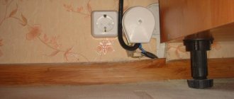
Before repairing an LED lamp, the device must be removed. You will need some tools; a thin screwdriver with a flat end, cross-shaped. If the connection was made using twists, you will need pliers with insulated handles, insulating tape and a multimeter to check the contacts. Tweezers are useful when working with small parts.
You will need a soldering iron with a thin tip and solder (it is advisable to use a special nozzle). A drill with a 2.5 mm drill can also be useful to disconnect the base part of the lamp by drilling out the fasteners. Several thin wires, 10 cm long. Attention! It is prohibited to carry out electrical work without special protected tools!
Design of LED chandeliers and visual inspection
Chandeliers with remote control appeared not so long ago. Few people are familiar with their device. When repairing LED ceiling chandeliers, you need to know the design, just in general terms. Let's take a closer look at what it may consist of.
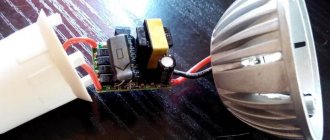
A simple LED chandelier consists of a housing, a controller unit or a driver. It is used as a voltage rectifier. It contains terminals, or terminal clamps, to which the mains power is connected. Then wires run from the block to the lamps. There can be from one wire, for a regular lamp, to 12 for a designer version of the device.
A more complex version of the product consists of an antenna, a control unit for the lighting itself, a voltage regulator or several units that perform automatic adjustment. Raster lamps can have several drivers and different types of LED elements and lamps. The inspection and repair of components depends on the specific type of lighting fixture.
Why you need to know or find out the design before you start repairing an LED chandelier. The reason is simple, you need to determine where the control units are located, inside the chandelier or in the lighting element itself, the lamp. Here we need the same LED chandelier circuit.
Repairing an LED chandelier operating without a remote control is easier. There is nothing complicated in it, they are assembled according to one type: one or more diodes (a compact bridge is possible), electrolytes (capacitors), a pair of resistances (resistors), and a coil with a winding. This is the simplest scheme without protection, there are many options, but now we will analyze the simplest scheme.
- After removing the lamp, inspect the board for the presence of visible defects, broken wires; the absence of such is a good sign.
- Remove the shade or decoration around the lamp, and unscrew the lighting elements. Inspect the base; burnt areas indicate poor contact. If there are any, try clearing them with a knife.
- Repack the terminal blocks or twists, tighten the screws on all parts. Having found no visible defects, we move on to inspecting the lamps. A variant of a block lamp, where the relays and lamps are located next to each other on a large board, is considered as a repair of the lamp described below.
- Repairing an LED chandelier with your own hands begins with determining the location of the breakdown or break.
Driver circuit for LEDs in a chandelier
The circuit is very simple, maybe it will be useful for someone in repairs:
Driver for powering serial chandelier LEDs. Electric scheme
Briefly the device. Ballast limit chain – C1, C2, R1. Most of the voltage drops on this circuit. Next, the alternating voltage is supplied to the diode bridge, and then to the filter R3, C3, R2.
If you need to slightly increase the voltage at the driver output under load (i.e., reduce its output resistance, see the part of the article with calculations), then you can increase the capacitance of the filter capacitor to 10...20 μF. Then the number of LEDs can be increased slightly.
And if you need to reduce the number of LEDs in a chandelier (for example, some have burned out), then you can reduce the ballast capacity by removing one of the capacitors C1, C2. It's experimental.
How 220 V LED lamps work
It is known that LEDs cannot operate directly from a 220 V network. To do this, they need additional equipment, which, most often, fails. We'll talk about it today. Let's consider the LED driver circuit, without which the lighting device cannot operate. At the same time, we will conduct an educational program for those who do not understand anything about radio electronics.
The driver in the LED lamp does the main jobgauss 12w driver
The 220 V LED lamp driver circuit consists of:
- diode bridge;
- resistance;
- resistors.
The diode bridge serves to rectify the current (converts it from alternating to direct). On the graph it looks like cutting off a half-wave of a sine wave. Resistors limit the current, and capacitors store energy, increasing the frequency. Let's look at the operating principle of a 220 V LED lamp.
The easiest way to check a lamp's LED circuit
Let's look at the easiest method for checking an LED circuit. First, fix the lamp using a cut plastic bottle with a smaller diameter. The lamp is inserted into it. To supply power, use an auxiliary power supply (if we are talking about a 12 or 24 V device).
Instead of ringing every LED in the circuit, you can resort to a simpler method. In turn, install a jumper between the contacts of each diode using tweezers. If there is no jumper, then take any wire, first stripping both ends and tinning the contacts.
It is important that the lamp is connected to the network at this moment. As soon as you close the contacts on the burnt out LED, the device will light up
If this does not happen, then more than one diode may have burned out.
Continue visual inspection of the circuit and look for burnouts, swollen capacitors, and examine each trace on the board. If broken contacts are found, perform soldering. If the circuit consists of 10 or fewer elements, then under no circumstances replace a burnt-out LED with a wire or jumper. This can lead to overloading the coils and burning out the diodes.
The LEDs in the chandelier stopped lighting
Let's look at it first
Design of a chandelier in which the LEDs do not light up
The chandelier is like this:
LED chandelier. LEDs connected in series do not work
If this is your first time seeing a chandelier from the back, I highly recommend my article on the construction of such chandeliers.
In this case, we have the simplest device: a chandelier for 2 groups, the 1st group - for 220V (4 E14 bulbs), the second group - 21 blue LEDs. The LEDs are connected in series through a driver, the device and circuit of which will be given below.
The controller that controls the chandelier using signals from the remote control is as follows:
Controller for a chandelier in which the LEDs do not work.
Not only is the controller Noname, but the label on the diagram is a complete mess; the conclusions should be like this:
- red – power phase,
- black – zero power,
- black – zero load (both wires are equivalent),
- white – phase output to load 1,
- yellow – phase output to load 2.
Well, to be completely grumpy, the third letter in the word “sacing” is wrong.
If the LED backlight on the chandelier stops working, then first of all you need to make sure that the controller supplies 220V power to the LED driver. Such controllers are easy to repair; read my article about Repairing LED chandelier controllers. There is also an exchange of experience among colleagues.
LED Serial Driver
On the body of this simplest device is the proud inscription LEDDRIVER.
Power supply for series-connected LEDs
In general, the Chinese call any power converters drivers, so there is no need to delude yourself.
Let's take a closer look at what is written on it:
Power supply for LEDs in a chandelier
Let's look at each power supply parameter:
- MHEN is a trademark. Identical devices are produced under the brands Jindel, ALED, Junyi, Jing Yi, and under other unpronounceable names.
- LED DRIVER – diode driver, as translated by an automatic translator. It may say LED Controller.
- 21-30 pcs – the number of LEDs that can be connected in series to this device.
- Model : GEL-11101A – model, it is also indicated on the board.
- Input : AC220-240 V 50 Hz. Everything should be clear here.
- Current : DC 60mA Max. This is the maximum current, which is not stabilized in any way; it is stabilized by the LEDs connected to the output. I wrote more about how this happens in the article about the Design and Connection of LED Strips.
- Output : Establish DC 3.0-3.2V. In fact, this is the voltage on one LED when the number within the specified limits is turned on (21-30 pcs.).
- LED 30 pcs Max – maximum number of LEDs.
- Ta, Tc – temperature of the environment and the device body.
- Jindel Electric is a Chinese manufacturer specializing in simple, cheap consumer electronics.
Checking the LEDs
A 3V LED is not an ordinary diode. A regular diode can be tested in the forward direction with a multimeter set to the “semiconductor testing” mode, and the readings will be about 800 Ohms. When the LEDs are tested in the forward direction, the LED lights up, albeit dimly. Otherwise, it doesn't light up. The multimeter does not show anything. More precisely, it shows infinity, i.e. "1".
In fact, when testing, a multimeter produces a voltage source of about 2V, and this is quite enough for a working LED to show signs of life.
To make everything completely clear, here's a picture:
Design, dimensions and pinout of an LED for a chandelier.
The anode to which the “plus” power is supplied is longer than the cathode to which the “minus” is supplied. The LED on the left shows a schematic diagram of a diode to make it clearer.
We apply the “plus” of the multimeter to the anode, and “minus” to the cathode. Thus, you can easily find out the polarity of the LED, its serviceability, and color. And based on the color, use the table above to find out the operating voltage.
In the chandelier that I was repairing, I started ringing the diodes, and realized that they would all have to be changed. Some showed 2-3 ohms in both directions, some showed 1000 ohms, some showed infinity. The result of inept repairs. Even if 1 or 2 LEDs are out of order, you should think about replacing everything, because... their parameters have inevitably changed (yes, we are all aging), and the new ones will have different parameters.
As a last resort, 1 or 2 LEDs can be replaced with jumpers or a resistor, the resistance of which will be calculated below. The jumper can only be installed if the remaining number of LEDs is not less than what is indicated on the driver. Otherwise, the “lucky ones” will not burn for long, but brightly.
Elena will also tell us how to check the LEDs in a chandelier:
Checking the Serial LED Power Driver
In general, all LEDs need to be changed. What about the driver?
To make sure the driver + LED tandem works, I assembled (soldered) the following bright design:
Checking the driver and LEDs before installing on the chandelier
As you can see, I use Vago terminals everywhere. Convenient and practical.
So, the measurement data is like this.
The output voltage of the driver (its device and its circuit will be for dessert) at idle (no load) is 305 V DC.
We connect a load of 22 LEDs (see photo above). We get - the voltage at the driver output is 80 V , the voltage on each LED is 80 / 22 = 3.63 V. According to measurements on each diode, this was approximately the case. As you can see, the voltage is slightly higher than the nominal value (3.0...3.4V), because the chandelier should shine brightly!
OK.
Now we connect 30 LEDs in series.
LEDs before installation in a chandelier. Connection for testing
Let's send current through the wires:
Checking 30 LEDs before installing in a chandelier
Measurement results. The driver output voltage is 107 VDC , one driver is 3.54 VDC .
That is, in principle, such a driver can power 40 diodes without a noticeable decrease in brightness.
That's it, the next day I installed these diodes with a driver in the chandelier, the owner was happy, and so was I.
Frequent malfunctions
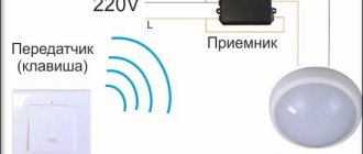
Most often, the product completely stops turning on using the radio remote control. This phenomenon is possible due to dead batteries. The cause may also be a malfunction of the controller on the ceiling. Sometimes not all groups of light bulbs light up. If you hear a clicking sound when you try to turn it on remotely, the controller is most likely working normally. In such situations, repairs come down to replacing the remote control and transformer. Incorrect operation can be observed only in some modes.
The transformer and sockets can be damaged if halogen lamps are selected incorrectly. Parts will have to be replaced. To avoid such damage, it is recommended to select light bulbs that are not too powerful.
Table of main malfunctions of a chandelier with a remote control.
Sometimes blinking and spontaneous mode changes are observed. The device turns off spontaneously. Breakdowns can occur due to low quality elements if cheap Chinese products were purchased.
Troubleshooting a remote controlled chandelier
Often, repairs to LED chandeliers need to be done due to overheating of the matrix itself. First, unscrew the fasteners and visually inspect the inside of the chandelier. Then they carefully try to move the board in place. Determine whether there is a break in the wires from the control unit, or whether the wire has burnt out due to overvoltage. If it's burnt out, solder it back in place. We check all the details one by one.
Then you will need an original chandelier diagram. Without it, you can only repair chandeliers without remote control. If there is a remote control unit, change the batteries in it with new elements. LED chandeliers with a control panel are common; here you will need an exact diagram of the chandelier controller to identify a breakdown.
The chandelier control unit is usually tightly sealed into a shell, and manufacturers draw circuits on it. These are just diagrams for connecting wires and lighting elements.
There are also blocks with a collapsible body, then the option is simplified. If the unit is not collapsible, use a tester to check the output signal to the lighting elements (LEDs). If there is no voltage supply, the reason may be a breakdown of the signal receiver. We disassemble it, visually check the contacts and tracks on the board, the integrity of the parts. If voltage is supplied to one lighting branch, then there is a breakdown in the control unit, and not in the signal receiver itself.
The burnt part can be unsoldered and ringed, first, all the resistances (see diagram) by placing an OM symbol on the device. Then the capacitance of the capacitors, fortunately there are symbols on them, polarity and type are also important when checking.
Designation on the diagram
If a discrepancy in the nominal value is detected, we resolder it.
The chandelier control unit is responsible for the intensity and burning modes of the LED elements. Violation of one of the circuits (in the lampshade version of the lamp) does not disable the unit; the fuse may have blown.
But still, check the blocks to see if there are melted places on them, yes, replace it with a new one. If the wires are connected incorrectly, only the parts in the power supply will burn. The regulator block is protected from excessive loads. It can be called according to the diagram.
Video:
Source and LED resistance calculations
Thanks to our circuit design teacher, Elena Mikhailovna Shibaeva.
Now, for fun, let’s calculate the output resistance of the power supply and the resistance of the LEDs. The calculations involve the good old Ohm with his famous law and the voltage divider formula.
So, for the case of 30 LEDs we have:
- Open circuit voltage of the current source – 305 V,
- Current source voltage under load – 107 V,
- The current in the circuit (yes, old Kirchhoff with his 1st law!) is 0.02 A.
We know the current from the declared parameters of the diodes, but we cannot rely on this figure for sure. Judging by the voltage on one diode, the current is much more!
To make the calculations clearer, I am attaching a diagram:
Circuit for measuring resistance
We assume that the input of the circuit is supplied with voltage from an ideal EMF source with zero internal resistance. A real source of electricity has an internal resistance Ri, which we will now calculate.
When measuring the open circuit voltage Un = Uхх = 305 V, since the input resistance of the voltmeter is much greater than the internal resistance of the source Ri.
When a load is connected, Un = 107 V, which means that the voltage dropping across the internal resistance of the source Ri is 305 – 107 = 198 V.
Knowing the current, let's calculate the internal resistance:
Ri = 198 V / 0.02 A = 9900 Ohm.
Is it a lot or a little? Everything is relative. In this case - in comparison with the load resistance:
Rн = 107 V / 0.02 A = 5350 Ohm.
This is the resistance of LEDs connected in series when a current of 0.02 A flows through them. This means that the resistance of one LED is 5350 Ohms / 30 = 178 Ohms.
This means that without changing the circuit parameters, one LED can be replaced with a 180 Ohm resistor. This coincides with the value obtained experimentally on one LED: 3.54 / 0.02 = 177 Ohms.
We see that the resistance of the power supply is greater than the load resistance. This means that in front of us is a current source. That is, when the load resistance (the number of LEDs) changes within certain limits, the current remains almost unchanged.
You can calculate the resistance of diodes, when there are 22 of them, it will be less due to the fact that the current will be greater, and the current-voltage characteristic of the diode is nonlinear.
Tricky question. Why, if the calculated resistance of the LED is 178 Ohms, does the tester in continuity mode (Ohmmeter) not show any resistance? Write your answer in the comments, I will be glad to know and savvy readers!
Okay, we've deviated somewhat from the topic.
Now - the promised dessert.