The definition of an electrical circuit implies a set of certain objects and devices connected to each other in a certain way, which are a path for the flow of electric current. A physical quantity characterized by the ratio of the charge, which is the cross-section of a conductor over time, to the value of this time interval - this is the current strength in the circuit.
{ ArticleToC: enabled=yes }
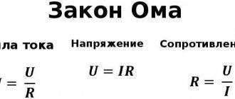
Meaning of Ohm's Law
Ohm's law determines the current strength in an electrical circuit at a given voltage and known resistance.
It allows you to calculate the thermal, chemical and magnetic effects of current, as they depend on the strength of the current. Ohm's Law is extremely useful in engineering (electronic/electrical) because it deals with three basic electrical quantities: current, voltage and resistance. It shows how these three quantities are interdependent at the macroscopic level.
If it were possible to characterize Ohm's law in simple words, then it would clearly look like this:
It follows from Ohm's law that it is dangerous to close a conventional lighting network with a conductor of low resistance. The current will be so strong that it can have serious consequences.
Problem 1.1
Calculate the current passing through a copper wire 100 m long, with a cross-sectional area of 0.5 mm2, if a voltage of 12 V is applied to the ends of the wire.
The task is simple; it consists in finding the resistance of a copper wire and then calculating the current strength using the Ohm's law formula for a section of the circuit. Let's get started.
Ohm's law for a complete circuit
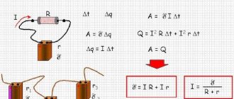
The formulation of Ohm's law for a complete circuit is that the current strength is directly proportional to the sum of the EMF of the circuit, and inversely proportional to the sum of the source and circuit resistances, where E is the EMF, R is the circuit resistance, r is the internal resistance of the source.
Questions may arise here. For example, what is EMF?
Electromotive force is a physical quantity that characterizes the work of external forces in an EMF source. For example, in a regular AA battery, EMF is a chemical reaction that causes charges to move from one pole to the other. The word electromotive itself means that this force moves a charge.
Each source has an internal resistance r, it depends on the parameters of the source itself. There is also a resistance R in the circuit; it depends on the parameters of the circuit itself.
The formula for Ohm's law for a complete chain can be presented in another form. Namely: the EMF of the circuit source is equal to the sum of the voltage drops on the source and on the external circuit.
To consolidate the material, we will solve two problems using the formula of Ohm's law for a complete circuit.
Problem 2.1
Find the current strength in the circuit if it is known that the circuit resistance is 11 ohms, and the source connected to it has an emf of 12 V and an internal resistance of 1 ohm.
Now let's solve a more difficult problem.
Problem 2.2
The EMF source is connected to a 10 ohm resistor using a copper wire 1 m long and with a cross-sectional area of 1 mm2. Find the current strength, knowing that the source emf is 12 V and the internal resistance is 1.9825 Ohms.
Let's get started.
A few examples
As a conclusion, we propose to consolidate the information received on several examples of problems in which you need to find the current strength.
Task 1: Calculate I in a circuit of two resistors in a series connection and in a parallel connection. R 1 and 2 Ohm resistors, 12 Volt power supply.
It is clear from the condition that you need to give two answer options for each of the connection options. Then, to find the current in a series connection, first add up the resistances of the circuit to get the total.
Then the current strength can be calculated using Ohm’s law:
When connecting two elements in parallel, R, the total can be calculated as follows:
Then further calculations can be carried out like this:
Task 2: calculate the current for a mixed connection of elements. The output of the power supply is 24V, and the resistors are: R1=1 Ohm, R2=3 Ohm, R3=3 Ohm.
First of all, you need to find the common R of R2 and R3 connected in parallel, using the same formula that we used above.
Now the diagram will look like:
Next, we find the current using the same Ohm’s law:
Now you know how to find the current strength, knowing the power, resistance and voltage. We hope the formulas and calculation examples provided helped you understand the material!
Electrical circuit
A source of electric current connected by wires to various electrical appliances and consumers of electrical energy forms an electrical circuit.
It is customary to depict an electrical circuit using diagrams in which the elements of the electrical circuit (resistances, current sources, switches, lamps, devices, etc.) are indicated with special icons.
The direction of current in a circuit is the direction from the positive pole of the current source to the negative pole. This rule was established in the 19th century. and has been observed ever since. The movement of real charges may not coincide with the conventional direction of the current. Thus, in metals, current carriers are negatively charged electrons, and they move from the negative pole to the positive one, that is, in the opposite direction. In electrolytes, the actual movement of charges may coincide with or be opposite to the direction of the current, depending on whether the ions are charge carriers - positive or negative.
The inclusion of elements in an electrical circuit can be serial or parallel.
Circuit with active resistance and inductance
For a circuit powered by alternating current, in which an inductor is connected, it is generally accepted that its active resistance is zero. In fact, both the coil wire and the connecting wires have a very small active resistance. Therefore the circuit will consume energy.
We recommend:
- Connection diagrams for a three-phase electric motor for 220 volts
- Frequency converter for single-phase electric motor
- Three-phase asynchronous electric motors: technical characteristics, types, features
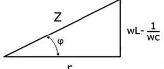
Therefore, when determining the total resistance of a circuit, it is necessary to take into account active and reactive resistance. However, they differ in character, so it is impossible to fold them in the usual way. You need to use the geometric addition method, which looks like this (figure below):
It is required to construct a triangle, one of whose sides is equal to the value of the active resistance, and the other - to the inductive one. The value of the total resistance corresponds to the third side, i.e. hypotenuse.
Impedance is measured in ohms and is designated “Z”. From the completed construction it is clear that it (the hypotenuse) is always greater than the active and inductive values (the legs) taken separately.
In the form of an algebraic expression it looks like this:
Here:
Z —impedance;
R - active;
XL - inductive.
This is what the relationship between the resistances of the elements that make up the circuit and the total looks like.
Ohm's law for a circuit
Ohm’s law for a section of a circuit can, of course, be described by the formula known from a school physics course: I=U/R, but I think it’s worth making some changes and clarifications. Let's take a closed electrical circuit and consider its section between points 1-2. For simplicity, I took a section of the electrical circuit that did not contain sources of emf (E).
So, Ohm's law for the section of the circuit under consideration has the form:
φ1-φ2=I*R, where
- I – current flowing through a section of the circuit.
- R is the resistance of this section.
- φ1-φ2 – potential difference between points 1-2.
If we take into account that the potential difference is voltage, then we come to the derivative formula of Ohm's law, which is given at the beginning of the page: U=I*R. This is the formula of Ohm's law for the passive section of the circuit (containing no sources of electricity).
Interesting on the topic: How to check a zener diode.
In an unbranched electrical circuit (Fig. 2), the current strength in all sections is the same, and the voltage in any section is determined by its resistance:
- U1=I*R1
- U2=I*R2
- Un=I*Rn
- U=I*(R1+R2+…+Rn
From here you can obtain formulas that are useful in practical calculations. For example:
U=U1+U2+…+Un or U1/U2/…/Un=R1/R2/…/Rn
The calculation of complex (branched) circuits is carried out using Kirchhoff's laws.
Ohm's law for a section of a circuit.
For EMF
Before considering Ohm's law for a complete (closed) circuit, I will give a sign rule for EMF, which states:
If inside an EMF source the current flows from the cathode (-) to the anode (+) (the direction of the field strength of external forces coincides with the direction of the current in the circuit, then the EMF of such a source is considered positive. Otherwise, the EMF is considered negative.
A practical application of this rule is the possibility of bringing several sources of EMF in a circuit to one with the value E=E1+E2+…+En, naturally, taking into account the signs determined by the above rule. For example (Fig. 3.3) E=E1+E2-E3. In the absence of a back-to-back source E3 (in practice this almost never happens), we have a widespread serial connection of batteries, in which their voltages are summed.
Example 2
The total current of a circuit containing two resistors R 1 = 70 Ohm and R 2 = 90 Ohm connected in parallel is 500 mA. Determine the currents in each of the resistors.
Two resistors connected in series are nothing more than a current divider. We can determine the currents flowing through each resistor using the divider formula, while we do not need to know the voltage in the circuit; we only need the total current and the resistance of the resistors.
Currents in resistors
In this case, it is convenient to check the problem using Kirchhoff’s first law, according to which the sum of currents converging at a node is equal to zero.
If you have any difficulties, read the article Kirchhoff's laws.
If you do not remember the current divider formula, then you can solve the problem in another way. To do this, you need to find the voltage in the circuit, which will be common to both resistors, since the connection is parallel. In order to find it, you must first calculate the circuit resistance
And then the tension
Knowing the voltages, we will find the currents flowing through the resistors
As you can see, the currents turned out to be the same.
Serial and parallel connection of elements
For elements of an electrical circuit (section of a circuit), a characteristic point is a serial or parallel connection. Accordingly, each type of connection is accompanied by a different pattern of current flow and voltage supply. In this regard, Ohm's law is also applied differently, depending on the option of including elements.
Circuit of series-connected resistive elements
In relation to a series connection (a section of a circuit with two components), the following formulation is used:
- I = I1= I2 ;
- U = U1+ U2 ;
- R = R1+ R2
This formulation clearly demonstrates that, regardless of the number of resistive components connected in series, the current flowing through a section of the circuit does not change in value. The magnitude of the voltage applied to the effective resistive components of the circuit is the sum and totals the value of the emf source.
In this case, the voltage on each individual component is equal to: Ux = I * Rx. The total resistance should be considered the sum of the values of all resistive components in the circuit.
Circuit of parallel connected resistive elements
In the case when there is a parallel connection of resistive components, the following formulation is considered fair in relation to the law of the German physicist Ohm:
- I = I1+ I2 … ;
- U = U1= U2 … ;
- 1 / R = 1 / R1+ 1 / R2 + …
Options for creating circuit sections of a “mixed” type, when parallel and serial connections are used, are not excluded. For such options, the calculation is usually carried out by initially calculating the resistive rating of the parallel connection. Then the value of the resistor connected in series is added to the result obtained.
Circuit power with inductor
Power, as is known from the high school curriculum, is the product of current and voltage, which are variable quantities. This means that power will also be a variable quantity in a circuit with active resistance and inductance.
Its value at a certain moment can be calculated by multiplying the values of current and voltage at the same moment. Having performed these actions for each time moment, we obtain graphs: a – for a circuit containing inductance, b – active:
The dotted curve p shows the power of an alternating current circuit, which consists of inductance. To construct it, algebraic multiplication is valid: multiplying two quantities with the same sign (two minuses or two pluses) results in a positive quantity, and multiplying them with different signs results in a negative quantity.
For a circuit that contains a resistor in addition to inductance, the power graph looks like this:
The power line is located on the time axis. This means that the generator and the circuit do not exchange energy, so the power supplied to the circuit by the generator is completely consumed by the circuit.
It turns out that with a greater phase shift between current and voltage, less power is consumed by the circuit.
Third party force
Nevertheless, current flows through the circuit; therefore, there is a force that “pulls” the charge through the source despite the resistance of the electric field of the terminals (Fig. 1).
Rice. 1. Third party force
This force is called a third party force; It is thanks to it that the current source functions. Third party force
has no relation to a stationary electric field - it is said to have a non-electric origin; in batteries, for example, it arises due to the occurrence of appropriate chemical reactions.
Let us denote by
the work of an external force to move a positive charge q inside a current source from the negative terminal to the positive. This work is positive, since the direction of the external force coincides with the direction of charge movement. The work of an external force is also called the work of a current source.
There is no external force in the external circuit, so the work done by the external force to move the charge in the external circuit is zero. Therefore, the work of an external force to move the charge
around the entire circuit comes down to the work of moving this charge only inside the current source. Thus, this is also the work of an external force to move charge throughout the circuit.
We see that the external force is non-potential - its work when moving a charge along a closed path is not zero. It is this non-potentiality that allows the electric current to circulate; a potential electric field, as we said earlier, cannot support a constant current.
Experience shows that work
directly proportional to the charge being moved. Therefore, the ratio no longer depends on the charge and is a quantitative characteristic of the current source. This relationship is denoted by: (1)
This quantity is called the electromotive force (EMF) of the current source. As you can see, EMF is measured in volts (V), so the name “electromotive force” is extremely unfortunate. But it has long been ingrained, so you have to come to terms with it.
When you see the inscription on the battery: “1.5 V”, then know that this is exactly the EMF. Is this value equal to the voltage created by the battery in the external circuit? It turns out not! Now we will understand why.
Tags
- algorithm for calculating circuits under non-sinusoidal periodic influences
- algorithm for calculating circuits of periodic non-sinusoidal current
- power balance
- CVC of a nonlinear element
- Vector diagram
- branches of communication
- mutual inductance
- mutual conductivity
- current-voltage characteristic of a nonlinear element
- Kirchhoff's second law
- Kirchhoff's second law for magnetic circuits
- input conductance
- voltage harmonics
- current harmonics
- Voltage generator
- current generator
- main contours
- graphical method for calculating nonlinear electrical circuits
- dynamic resistance
- differential resistance
- two-wire line capacity
- coaxial cable capacity
- capacitor capacity
- single wire line capacity
- parallel plate capacitor capacitance
- cylindrical capacitance
- Ampere's law
- Biot-Savart-Laplace's law
- Ohm's law
- total current law
- law of electromagnetic induction
- Kirchhoff's laws
- inductance
- two-wire line inductance
- single wire line inductance
- solenoid inductance
- steel reel
- Capacitor in DC circuit
- loop currents
- crest factor
- harmonic distortion factor
- distortion factor
- magnetic coupling coefficient
- transformer power factor
- transformation ratio
- form factor
- piecewise linear approximation
- magnetic constant
- magnetic circuit
- magnetic leakage flux
- active two-terminal method
- two node method
- loop current method
- overlay method
- nodal stress method
- nodal potential method
- equivalent generator method
- EMF equivalent source method
- Equivalent transformation method
- methods for calculating magnetic circuits
- independent circuits
- nonlinear element
- non-sinusoidal periodic current
- generalized Ohm's law
- support node
- main magnetic flux
- parallel connection of capacitors
- Kirchhoff's first law
- Kirchhoff's first law for magnetic circuits
- series connection of capacitors
- series oscillating circuit
- DC current component
- copper losses
- steel losses
- led transformer
- Examples of circuit calculations for non-sinusoidal periodic influences
- principle of reciprocity
- principle of compensation
- current harmonics calculation
- magnetic circuit calculation
- calculation of nonlinear DC circuits
- calculation of non-sinusoidal current circuits
- Capacitor circuit calculation
- calculation of a circuit with non-sinusoidal periodic sources
- Resonance in an electrical circuit
- problem solving magnetic circuits
- Ampere power
- Lorentz force
- Symbolic method
- intrinsic conductivity
- static resistance
- spherical capacitor
- equivalent source theorem
- Thevenin's theorem
- topographic diagram
- Transformers
- three phase system
- specific magnetic field energy
- transformer equations
- Circuits with capacitors
- partial currents
- phase rotation
- Self-induced emf
- transformer equivalent circuit
- electrical constant
- electrical capacity
- magnetic field energy
Electrical circuit efficiency
It is not difficult to understand why the resistor
called the payload. Imagine it's a light bulb. The heat generated by the light bulb is useful, since thanks to this heat the light bulb fulfills its purpose - giving light.
The amount of heat released by the payload
for time, let's denote .
If the current in the circuit is equal to
, That
A certain amount of heat is also released at the current source:
The total amount of heat released in the circuit is equal to:
The efficiency of an electrical circuit is the ratio of useful heat to total heat:
The efficiency of the circuit is equal to unity only if the current source is ideal
.
Joule-Lenz law
Another task that can confuse even a more or less experienced student is to determine the current strength if the time, resistance and amount of heat generated by the conductor are known. To do this, remember the Joule-Lenz law.
Its formula looks like this:
Q=I 2 Rt
Then do the calculation like this:
I 2 =QRt
Or enter the right side of the equation under the root:
I=(Q/Rt) 1/2
Where and when can Ohm's law be applied?
Ohm's law in the form mentioned is valid within fairly wide limits for metals. It is carried out until the metal begins to melt. A less wide range of applications is in solutions (melts) of electrolytes and in highly ionized gases (plasma).
When working with electrical circuits, sometimes you need to determine the voltage drop across a certain element. If it is a resistor with a known resistance value (it is marked on the case), and the current passing through it is also known, you can find out the voltage using Ohm’s formula without connecting a voltmeter.
Sources
- https://toe.1c-umi.ru/lekcii/lekciya_6_-_zakon_oma/
- https://www.calc.ru/Zakon-Oma-Dlya-Polnoy-Elektricheskoy-Tsepi.html
- https://ElectroInfo.net/teorija/vse-o-zakone-oma-prostymi-slovami-s-primerami-dlja-chajnikov.html
- https://ege-study.ru/ru/ege/materialy/fizika/eds-zakon-oma-dlya-polnoj-cepi/
- https://OFaze.ru/teoriya/zakona-oma-dlya-polnoj-tsepi
Loop current method
The method of calculating electrical circuits discussed above when analyzing large and branched circuits leads to unreasonably labor-intensive calculations, and therefore is rarely used. The loop current method is more widely used, allowing a significant reduction in the number of equations. In this case, instead of currents in the branches of an electrical circuit, the so-called loop currents are determined using Kirchhoff’s second law. Thus, the number of required equations will be equal to the number of independent circuits. As an example, let's calculate the circuit shown in the figure below.
If we were to calculate the circuit using the method of Ohm's and Kirchhoff's laws, then it would be necessary to solve a system of five equations. To calculate using the loop current method, only three equations are needed.
At the beginning of the calculation, independent contours are identified, in our case these are: E1R1R2E2, E2R2R4E3R3 and E3R4R5. Then the circuits are assigned an arbitrarily directed circuit current, which has the same direction for all sections of the selected circuit; in our case, for the first circuit the circuit current will be Ia, for the second - Ib, for the third - Ic. As can be seen from the figure, some loop currents correspond to currents in the branches
The remaining currents can be found as the difference between two loop currents
As a result of the choice of loop currents, it is possible to create a system of equations according to Kirchhoff’s second law
Let's calculate the circuit shown in the figure above with the following parameters E1 = E3 = 100 V, E2 = 50 V, R1 = R2 = 10 Ohm, R3 = R4 = R5 = 20 Ohm. Let's write the system of equations
As a result of solving the system, we obtain Ia = I1 = 4.286 A, Ib = I3 = 3.571 A, Ic = I5 = -0.714 A, I2 = -0.715 A, I4 = 4.285 A. Just like in the previous case, if the currents are negative, This means that the actual direction is opposite to the accepted one. Thus, the currents I2 and I5 have the opposite direction to those shown in the figure.