Outside forces
In order for there to be an electric current in a conductor for a long time, it is necessary to create certain conditions. To do this, in certain sections of the circuit, in addition to the forces of the stationary field, so-called third-party forces act. Sections of the chain in which there is the action of additional, third-party forces are called heterogeneous. In this case, the movement of charges occurs under the influence of forces of a non-electrostatic nature acting in devices called direct current sources.
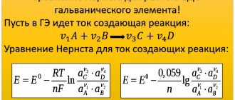
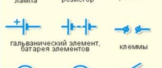
The forces that move electric charges inside a direct current source against the direction of the electrostatic field forces are called extraneous forces. Extraneous forces in a galvanic cell or battery arise as a result of electrochemical reactions occurring between the particles of the metal electrode and the electrolyte molecules. In DC generators, an external force is the force arising from the action of a magnetic field on a moving electric charge. The operation of the current source is similar to the function of a pump that forces fluid to move (pumps) through the pipes of a closed hydraulic circuit. Under the influence of external forces, charges move inside the current source against the forces of the electrostatic field, due to which a constant electric current is maintained in a closed circuit for a long time.
Rice. 1. DC sources, batteries, galvanic cells, generators.
Interpretation and limits of applicability of Ohm's law
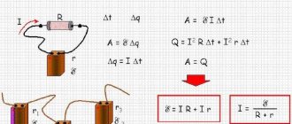
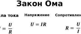
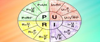
If it is necessary to determine one of the quantities: current, voltage or resistance for a homogeneous circuit, then use the formula, the formulation of which is shown in the figure.
Ohm's law in a triangle
For convenience of solving the identities, quantities are depicted in a triangle. Now, using the first formula, knowing the circuit resistance and current, you can calculate the voltage that acts on the closed circuit. Knowing the voltage and resistance of the circuit, you can determine the current using the 2nd formula. Using the 3rd formula, the load resistance is calculated, knowing the voltage and current.
There are exceptions when Ohm's law is not followed. Examples:
- In variable EMF, if the load is inductive or capacitive in nature. As the frequency increases, due to the inertia of charge carriers, the laws of electrodynamics come into force. Capacitors and inductors as resistance for alternating current, oscillating circuit.
- For substances that exhibit superconductivity at low temperatures. High precision instrument sensors, superconducting solenoids, superconducting cables with a current of 5,000 A.
- At high temperatures, when the conductor begins to exhibit a nonlinear resistance characteristic. Tungsten filament of an incandescent lamp, spirals of heating elements.
- At high voltages, when dielectric breakdown occurs. Spark plugs for carburetor engines, tips for protection against glow discharge of high-voltage power lines.
- In gas-filled fluorescent and vacuum lamps. Fluorescent lamps, vacuum indicators, glow discharge indicators.
- In semiconductor devices with pn junctions and in nonlinear semiconductors. These are LEDs, zener diodes, transistors, electronic devices.
Interesting. Ohm's law is used in differential form when there are several emfs, or a chain of conductors is under the influence of external forces. For example, when charging batteries with solar panels or other EMF, also in generators with excitation windings, if they are differentiated.
Measuring bridge
Conductor materials to which Ohm's law applies are called ohmic or linear conductors. Those whose resistance has a functional dependence on the current intensity are nonlinear. Metals can behave this way at extremely low or high temperatures.
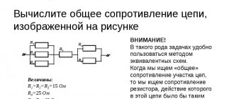
Mixed connection of conductors
A mixed connection of conductors is a connection in which some of the conductors are connected in series and some in parallel.
Important! To calculate the total resistance of such a section or find the current and voltage at such a connection, you need:
- break it into simple sections with conductors connected in series or parallel;
- find the total (equivalent) resistance of each of these sections;
- draw up an equivalent circuit. Usually a circuit of equivalent resistances connected in series is obtained;
- calculate the resistance of the resulting circuit.
If in the circuit it is not possible to identify areas with serial or parallel connection of conductors, then you can use the following rule: points with the same potentials can be connected and disconnected, no current flows between such points.
In the figure, if ( R_1=R_2,R_4=R_5, ) then the potentials of points 1 and 2 are equal. The resistor ( R_3 ) can be removed in the equivalent circuit - no current flows through it.
Points with equal potentials exist in circuits with an axis or plane of symmetry relative to the connection points of the current source.
If the circuit is symmetrical about the axis passing through the current entry and exit points, then the points of equal potential are located at the ends of symmetrical resistances (the same currents flow through them).
If the circuit is symmetrical about an axis perpendicular to the line on which the current entry and exit points lie, then the points of equal potential are located at the intersection of this axis with the conductors.
If there are no sections in the circuit with a known type of connection and there are no points with equal potential, then Kirchhoff’s rules are used to calculate such circuits.
Kirchhoff's rules:
- The algebraic sum of current strengths converging at a node is equal to zero:
Currents entering the node are considered positive, and currents leaving the node are considered negative.
- In any closed circuit, arbitrarily chosen in a branched circuit, the algebraic sum of the products of the current strengths and the resistance of the corresponding sections of this circuit is equal to the algebraic sum of the emfs present in the circuit:
Circuit calculation procedure:
- choose the direction of currents in the entire circuit;
- write down the current equations for the nodes;
- write down equations for the selected contours. Arbitrary closed contours are selected so that each new contour contains at least one section that is not included in the previously considered contours;
- solve the resulting system of equations.
Algorithm for solving problems to determine the current, voltage or resistance in a section of a circuit:
- draw a diagram of the circuit and indicate all the elements on it;
- establish which circuit elements are connected in series and which in parallel;
- arrange the currents and voltages in each section of the circuit and write down for each branch point (if any) the current equations and equations relating the voltages in the sections of the circuit;
- using Ohm's law, establish a connection between currents, voltages and EMF;
- if any switching of resistances or sources is made in the circuit, create equations for each mode of operation of the circuit;
- solve the resulting system of equations for an unknown quantity;
- check the solution.
Inhomogeneous section of the DC circuit
Definition of main parameters and processes:
- the movement of charges (q) is characterized by density, which depends on the cross-sectional area (S) and current strength;
- at concentration (n), you can calculate the number of unit charges (q0) moved per unit time;
- this quantity can be depicted as a cylindrical section of a conductor with volume (V):
q = q0*n*V.
If you connect the battery terminals to a conductor, the power supply will be discharged. To maintain the process of moving charges for a long time, you can create a path closed in a ring. However, even in this case, the free drift of electrons is limited by joint collisions and the opposition of charges of the molecular lattice of the material. To compensate for resistance, it is necessary to apply additional “third-party” forces.
An example of a non-uniform section of a chain
The figure shows the factors that should be taken into account. To calculate the tension at any point in this circuit, you need to sum up the vector components Eq and Est (Coulomb and external forces, respectively)
The given Ohm's law for a non-uniform area determines that the current strength (I12) = voltage in a given area (U12) / total electrical resistance (R).
To transfer a unit charge q from point “1” to point “2”, it is necessary to perform work A12. This will require the creation of a certain potential difference (ϕ1-ϕ2). A direct current source creates an electromotive force (EMF), which is capable of moving charge through the circuit. The total stress will contain the sum of the listed forces.
Below are the formulas characterizing the considered example:
- A12/q = ϕ1 – ϕ2;
- Ast/q = E12;
- U = A12/q + Ast/q = ϕ1 – ϕ2 + E12;
- I = (ϕ1 – ϕ2 + E12)/ R.
An integrated version of the representation of the processes under consideration will give a similar result.
For your information. When performing calculations, the actual polarity of the DC source must be taken into account. Depending on the connection, the corresponding EMF will promote or hinder the movement of charge.
The following example demonstrates the solution to a practical problem. It is necessary to calculate the current in the circuit, which is made up of a power source with EMF = 40V and wiring with electrical resistance R = 5 Ohm. The potentials measured at the output are:
ϕ1= 20V; ϕ2=10V.
By substituting the values into the formula, you can get the desired result:
(20-10+40)/5 = +10A.
The plus sign means that the current flows in the direction from point “1” to “2”.
If we consider the process in differential form, we can imagine a “cloud” created from a certain number (N) of charges. It moves in the conductor with a certain drift speed (Vdr). Three types of forces act on it:
- Coulomb - Fcoul;
- third-party – Fc;
- crystal lattice resistance – Fsp.
The latter indicator will depend on the characteristics of the material. It can be expressed as specific conductivity. The current density vector will be equal to the sum of the EMF vectors (Coulomb and extraneous nature) divided by the resistivity.
Use for AC
As is known, in an alternating current circuit there is both active and reactive resistance. The first of them coincides with how this quantity was understood in the time of Georg Ohm. However, inductive and capacitive reactance also inhibit the movement of electrons. In this case, Ohm's law for alternating current applies.
To use this law in such circuits, instead of ohmic resistance, total resistance should be considered, which takes into account the total effect of the active and reactive components of the resistance.
In the presented circuit, the total resistance is denoted as Z. Ohmic, inductive and capacitive - R, XL and XC, respectively. Ohm's law for an alternating current circuit takes into account all these variations. The calculation formula implies that the addition of resistances occurs according to the vector rule.
To determine all resistances, a right triangle is used, one leg of which expresses the active resistance, and the second - the reactive one. The latter is equal to the difference between inductive and capacitive reactances. The determination of the total is carried out according to the Pythagorean theorem, according to which the length of the hypotenuse is equal to the square root of the sum of the squares of the legs.
Resistance
The resistance of conductors and other substances (semiconductors and dielectrics) is due to the fact that charged particles interact (collide) with crystal lattice sites and atoms of various impurities and defects, which leads to charge deceleration.
Observations have shown that the resistance of a conductor is directly proportional to its length L and inversely proportional to its cross-sectional area S:
$ R = ρ * { L \over S } $ (5),
Rice. 2. Electric current I in a metal cylindrical conductor, length L, area S, electric field E.
The unit of resistance is Ohm, equal to:
$ = {\over } $ (6).
The unit of measurement of resistivity ρ shows what resistance a conductor 1 meter long with a cross-sectional area of 1 m2 has. The resistivities of all known materials have been measured and summarized in reference tables.
Rice. 3. Example of a reference table for specific conductivities of different substances
The values of ρ in the reference tables are usually given for a normal temperature of 20C, because The resistivity value depends on the ambient temperature T, and is described by the formula:
$ ρ = ρ_0 * (1 + α * T) $ (7),
where: ρ is the resistivity at 0K, α is the temperature coefficient of resistance.
What have we learned?
So, we have learned that Ohm’s law for a homogeneous section of a circuit is formulated as follows: the current strength I for a conductor in a homogeneous section of the circuit is directly proportional to the voltage U in this section and inversely proportional to the resistance of the conductor R. Sections of the electrical circuit in which there are no current sources are called homogeneous . Specific electrical resistance of a substance ρ is a value characterizing the ability of a substance to resist.
Conclusion
As mentioned at the beginning of the article, all applied electrical engineering is based on the law compiled by Ohm. Ignorance of this basic tenet can lead to incorrect calculations, which in turn will cause an accident.
Training electricians as specialists begins with studying the theoretical foundations of electrical engineering. And the first thing they should remember is Ohm’s law, since almost all calculations of the parameters of electrical circuits for various purposes are made on its basis.
Understanding the basic law of electrical engineering will help you better understand the operation of electrical equipment and its main components. This will have a positive effect on maintenance during operation.
Independent testing, development, as well as experimental study of equipment components - all this is greatly simplified if you use Ohm’s law for a section of the circuit. In this case, it is not necessary to carry out all the measurements; it is enough to take some parameters and, after carrying out simple calculations, obtain the required values.
Action of electromotive forces
Electromotive force (EMF) is a scalar quantity that characterizes the work of non-electric forces that cause a potential difference to be produced at the output.
Additional Information. A scalar quantity is when it can only be expressed by a specific value. In contrast to a vector quantity, which is determined not only by the value, but also by the direction.
EMF is used in generators that convert any work A (joule) into electrical work. For this purpose, the following types of energy can be used depending on their origin:
- Mechanical induction. The EMF output occurs when a conductor crosses magnetic field lines;
- Mechanical piezoelectric. EMF occurs when certain substances are deformed;
- Light energy. Here, EMF appears in semiconductors when light rays act on them;
- Thermal energy. EMF is formed when contacts of dissimilar conductors are at different temperatures;
- Chemical energy. The occurrence of EMF occurs due to chemical reactions.
Depending on the nature of the energy and the design of the generator, both variable and constant EMF can occur. The variable can be either sinusoidal (magnetic induction generators) or pulsed (piezo lighters). Constant EMF is converted mainly from chemical (batteries, batteries), light (photocells) energies and temperature (Peltier elements).
Current generators
EMF creates a potential difference on opposite conductors. If you do not connect terminals at which there is a potential difference with a conductor, then there will be no current in the circuit. Therefore, no energy will be wasted. A potential difference will remain at the terminals. No work needs to be done to maintain this difference.
If a conductor with a load is connected to terminals with a potential difference, then an electric current will flow through it, performing work on the load. In this case, the potential difference at the terminals will tend to 0, which will lead to a drop in the current to 0. To maintain the potential difference at a stable value, it is necessary for the EMF to receive energy. This energy expends work equal to that performed in the load.
Practical use
An example is shown in the figure.
We apply the law to any part of the chain
Using such a plan, you can calculate all the necessary characteristics for an unbranched section. Let's look at more detailed examples. Finding the current strength Let's now consider a more specific example, let's say there is a need to find out the current flowing through an incandescent lamp. Conditions:
- Voltage – 220 V;
- R filament – 500 Ohm.
The solution to the problem will look like this: 220V/500Ohm=0.44 A.
Let's consider another problem with the following conditions:
- R=0.2 MOhm;
- U=400 V.
In this case, first of all, you will need to perform the conversion: 0.2 MOhm = 200000 Ohm, after which you can begin to solve: 400 V/200000 Ohm = 0.002 A (2 mA). Calculating voltage To solve, we will also use Ohm's law. So the task:
- R=20 kOhm;
- I=10 mA.
Let's transform the source data:
- 20 kOhm = 20000 Ohm;
- 10 mA=0.01 A.
Solution: 20000 Ohm x 0.01 A = 200 V.
Don't forget to convert the values, since quite often the current can be indicated in milliamps.
Resistance.
Despite the fact that the general form of the method for calculating the parameter “R” resembles finding the value “I”, there are fundamental differences between these options. If the current can vary depending on two other parameters, then R (in practice) has a constant value. That is, at its core, it is represented as an unchanging constant.
If the same current (I) passes through two different sections, while the applied voltage (U) differs, then, based on the law we are considering, we can confidently say that where the low voltage “R” will be the smallest.
Let's consider the case when there are different currents and the same voltage in unconnected areas. According to Ohm's law, a large current will be characteristic of a small parameter "R".
Let's look at a few examples.
Let's say there is a circuit to which the voltage U=50 V is applied, and the consumed current I=100 mA. To find the missing parameter, you should use 50 V / 0.1 A (100 mA), in the end the solution will be 500 Ohms.
The current-voltage characteristic allows you to clearly demonstrate the proportional (linear) dependence of the law. The figure below is a graph for a section with a resistance equal to one ohm (almost like a mathematical representation of Ohm's law).
Image of the current-voltage characteristic, where R=1 Ohm
Illustration of current-voltage characteristics
The vertical axis of the graph displays the current I (A), the horizontal axis displays the voltage U(V). The graph itself is presented in the form of a straight line, which clearly displays the dependence on the resistance, which remains unchanged. For example, at 12 V and 12 A, “R” will be equal to one ohm (12 V/12 A).
Please note that the current-voltage characteristic shown only shows positive values. This indicates that the circuit is designed to allow current to flow in one direction. Where the opposite direction is allowed, the graph will continue to negative values.
Note that equipment whose current-voltage characteristic is displayed as a straight line is called linear. The same term is used to refer to other parameters.
In addition to linear equipment, there are various devices whose “R” parameter can change depending on the current or applied voltage. In this case, Ohm's law cannot be used to calculate the dependence. Equipment of this type is called nonlinear; accordingly, its current-voltage characteristics will not be displayed as straight lines.
Statement of the law
The law refers to the basic position in electrical engineering.
Ohm's formula for a section of a chain:
V = IR, where:
- V - voltage between 2 points, V;
- R is resistance, a property of a material used to describe opposition to the flow of current, Ohm;
- I is the current strength in a section of the circuit - the flow of electrons or electron-deficient atoms, determined in A.
Ohm's Law
Converting proportionality into an equation results in a constant "R" - resistance.
Dependence of current and resistance
In the 1st case, Ohm's law for a section of the circuit is expressed by the formula: I = V/R, it is clear that the electric current is calculated by dividing V by R. The 2nd option states that V is calculated if I and R in the circuit are known. It is obvious from the equation that if I or R increases while the other does not change, the voltage must also increase.
Current vs Voltage Relationship
The third option confirms that it is possible to calculate R in a circuit; before finding the resistance of a section of a circuit using the formula, you need to know two other indicators. If the current is kept constant, then an increase in voltage will lead to an increase in resistance.
Closed network
Classic formulation
This is a simple version of the interpretation, known to us from school. Homogeneous open section of an electrical circuit
The formula in integral form will have the following form:
Formula in integral form
That is, by raising the voltage, we thereby increase the current. While an increase in a parameter such as “R” leads to a decrease in “I”. Naturally, in the figure the circuit resistance is shown as one element, although it can be a serial, parallel (even arbitrary) connection of several conductors.
We will not present the law in differential form, since in this form it is used, as a rule, only in physics.
Ohm's law for a non-uniform section of a circuit
A physical quantity equal to the ratio of the work of external forces Ast when moving a charge q from the negative pole of a current source to the positive pole to the value of this charge is called the electromotive force (EMF) of the source Eemf:
$ E_{emf} = {A_{ct}over q} $ (1).
Chapter 10. Rogue waves and visibility waves
Thus, the EMF is equal to the work done by external forces when moving a unit positive charge. When a single positive charge moves along a closed direct current circuit, the work of the electrostatic field is zero, and the work of external forces is equal to the sum of all the emfs acting in this circuit.
The work of electrostatic forces to move a unit charge is equal to the potential difference $ Δφ = φ_1 – φ_2 $ between the starting and ending points 1 and 2 of the inhomogeneous section. The work of external forces is equal, by definition, to the electromotive force Eemf acting in a given area. Therefore the total work is equal to:
$ U_п = φ_1 – φ_2 + E_{edc} $ (2).
The value Up is called the voltage on circuit section 1–2. In the case of a homogeneous area, the voltage is equal to the potential difference:
$ U_п = φ_1 – φ_2 $ (3).
The German researcher Georg Simon Ohm at the beginning of the 19th century established that the strength of the current I flowing through a homogeneous conductor (i.e., a conductor in which no external forces act) is proportional to the voltage U at the ends of the conductor:
$I = {U over R}$ (4).
Rice. 2. Portrait of Georg Ohm.
The R value is the electrical resistance. Equation (4) expresses Ohm's law for a homogeneous section of the chain. For a section of a circuit containing an emf, Ohm’s law is written as follows:
$ U_п = I * R = φ_1 – φ_2 + E_{emf} = Δ φ_{12} + E_{emf}$ (5).
This equation is called the generalized Ohm's law for an inhomogeneous section of the chain.
Accepted units of measurement
It must be taken into account that all calculations must be carried out in the following units of measurement:
- voltage – in volts;
- current in amperes
- resistance in ohms.
If you come across other quantities, they will need to be converted to generally accepted ones.
Current strength I
Let a current flow in some conductor. That is, there is a directed movement of charged particles - for example, these are electrons. Each electron has an elementary electric charge (e= -1.60217662 × 10⁻¹⁹ Coulombs). In this case, a specific electric charge equal to the sum of all charges of flowing electrons will pass through a certain surface in a certain period of time.
The ratio of charge to time is called current strength. The more charge passes through a conductor in a certain time, the greater the current. Current strength is measured in Amperes.
Voltage U, or potential difference
This is exactly the thing that makes electrons move. Electric potential characterizes the ability of a field to do work to transfer charge from one point to another. So, between two points of a conductor there is a potential difference, and the electric field does work to transfer charge.
A physical quantity equal to the work of the effective electric field during the transfer of electric charge is called voltage. Measured in Volts. One Volt is the voltage that, when moving a charge of 1 C, does work equal to 1 Joule.
Resistance R
Current, as we know, flows in a conductor. Let it be some kind of wire. Moving along a wire under the influence of a field, electrons collide with atoms of the wire, the conductor heats up, and the atoms in the crystal lattice begin to vibrate, creating even more problems for the electrons to move. This phenomenon is called resistance. It depends on temperature, material, conductor cross-section and is measured in Ohms.
Monument to Georg Simon Ohm
Ohm's law for a non-uniform section of a circuit
When an electric current passes in a closed circuit, free charges are subject to forces from a stationary electric field and external forces. In this case, in certain sections of this circuit, the current is created only by a stationary electric field. Such sections of the chain are called homogeneous. In some sections of this circuit, in addition to the forces of a stationary electric field, external forces also act. The section of the chain on which external forces act is called a non-uniform section of the chain.
In order to find out what the current strength in these areas depends on, it is necessary to clarify the concept of voltage.
Rice. 1
Let us first consider a homogeneous section of the chain (Fig. 1, a). In this case, the work to move the charge is performed only by the forces of a stationary electric field, and this section is characterized by a potential difference. Potential difference at the ends of the section
where AK is the work done by the forces of a stationary electric field. The inhomogeneous section of the circuit (Fig. 1, b) contains, in contrast to the homogeneous section, a source of EMF, and the work of the electrostatic field forces in this section is added to the work of external forces. A-priory,
where q is a positive charge that moves between any two points in the chain; — potential difference between points at the beginning and end of the section under consideration;
Then they talk about tension for tension: Estatic.e.p. = Ee/stat.p. + Est. Voltage U in a section of a circuit is a physical scalar quantity equal to the total work of external forces and electrostatic field forces to move a single positive charge in this section:
From this formula it is clear that in the general case, the voltage in a given section of the circuit is equal to the algebraic sum of the potential difference and the emf in this section. If only electric forces ( = 0) act on the area, then
Thus, only for a homogeneous section of the circuit the concepts of voltage and potential difference coincide.
Ohm's law for a non-uniform section of a chain has the form:
where R is the total resistance of the inhomogeneous section.
EMF can be either positive or negative. This is due to the polarity of the inclusion of the EMF in the section: if the direction created by the current source coincides with the direction of the current passing in the section (the direction of the current in the section coincides inside the source with the direction from the negative pole to the positive), i.e. EMF promotes the movement of positive charges in a given direction, then > 0, otherwise, if the EMF prevents the movement of positive charges in a given direction, then
Work of electric current. Joule–Lenz law
Current work is the work done by the electric field forces that create an electric current.
The work done by the current on a section of the circuit is calculated by the formula:
Using the formula of Ohm's law for a section of a circuit, the work of the current can be calculated as follows:
The work of current in a closed circuit is found by the formula:
When direct current flows through a metal conductor, electrons collide with positive ions located at the nodes of the crystal lattice. At the same time, electrons transfer energy to them. This leads to heating of the conductor. The amount of heat released in the conductor during time ( t ) is equal to:
This formula expresses the Joule-Lenz law: the amount of heat released when a current passes through a conductor is directly proportional to the square of the current strength, the time of its passage and the resistance of the conductor.
Movement of current through inhomogeneous conductors
The potential difference caused by the EMF will produce a voltage at the generator terminals. EMF is a scalar quantity. When a conductor is connected to the terminals, a current will flow through it, the density of which is expressed, for example, Ī. This is already a vector quantity. If the current is created only by the potential difference across the terminals, then the potential and current density vectors will coincide. Such a conductor is called homogeneous. Ohm's law for a homogeneous section of a chain:
I=U/R.
Tension vector
A non-uniform conductor, in addition to the forces that are formed by potential differences, has external forces. To determine the current density Ī, Ohm's law is used in differential form for inhomogeneous conductors:
Ī=γ(E+Ē₁+ Ē₂+ Ēn).
The vectors and each section of the conductor are added, E is the voltage created by the potential difference at the conductor terminals (scalar quantity). Ē₁, Ē₂, Ēn – vector values of the intensity of the first, second and nth external forces.
Since γ is the conductivity of the conductor, the inverse of the resistance, ϕ₁ is the potential at the 1st point, ϕ₂ is the potential at the 2nd point, then Ohm’s law for the inhomogeneous section of the circuit from the 1st to the 2nd point will be written as follows:
Ī =(ϕ₁ – ϕ₂+ Ē)/R.
To familiarize yourself with metals and their resistivity:
- Silver – 1.6×10ˉ⁸Ohm×m;
- Copper – 1.72×10ˉ⁸ Ohm×m;
- Aluminum – 2.6×10ˉ⁸ Ohm×m;
- Brass – 3…7.0×10ˉ⁸ Ohm×m;
- Bronze – 8.0×10ˉ⁸ Ohm×m;
- Iron – 9.8×10ˉ⁸ Ohm×m;
- Lead – 2.0×10ˉ⁶Ohm×m;
- Graphite – 3…5.0×10ˉ⁵Ohm×m.
Ohm's law for a complete circuit
If a closed circuit consists of a circuit resistance equal to R and a current source with electromotive force Eemf and internal resistance r, then in this case the circuit current I will be equal to:
$ I = {E_{emf} over R + r} $ (6).
Expression (6) is called Ohm's law for a complete circuit: the current in a complete circuit is equal to the emf of the source divided by the sum of the resistances of the homogeneous and inhomogeneous sections of the circuit.
Conductors that exactly comply with Ohm's law are called linear, since the graph of current I versus voltage U is depicted as a straight line. It should be noted that there are many materials that do not obey Ohm's law, such as semiconductors or gas discharge lamps. For metal conductors, deviations from the linear dependence appear at high currents, since the resistance of metals increases with increasing temperature.
Rice. 3. Graph of the resistance of metal conductors versus temperature.
Parallel and series connection of conductors
Conductors in electrical circuits can be connected in series and in parallel.
Series connection of conductors
In a series connection, the beginning of one conductor is connected to the end of another.
In a series connection, the current strength in all conductors is the same:
The total voltage ( U ) on the conductors is equal to the sum of the voltages on the individual conductors:
The voltage on the conductors is directly proportional to their resistance:
The total resistance is equal to the sum of the resistances of the conductors forming the circuit:
If the conductors have the same resistance, then the total resistance is found by the formula:
where ( n ) is the number of conductors, ( R_i ) is the resistance of the conductor.
Parallel connection of conductors
In a parallel connection, conductors are connected between the same pair of points. If three or more conductors are connected at this point, then it is called a node in the electrical circuit.
In a parallel connection, the voltage on all conductors is the same:
The sum of the currents flowing through the conductors is equal to the current in an unbranched circuit:
This is a consequence of the fact that charges cannot accumulate at branch points in the chain.
The current strengths in the branched parts of the circuit are inversely proportional to their resistances:
The reciprocal of the total resistance of the circuit is equal to the sum of the reciprocals of the resistances of parallel-connected conductors:
If the conductors have the same resistance, then the total resistance is found by the formula:
where ( n ) is the number of conductors, ( R_1 ) is the resistance of the conductor.
If two conductors are connected in parallel, the total resistance is calculated using the formula: