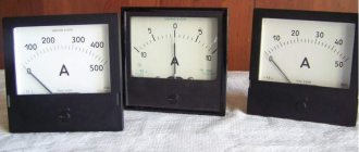
In nature, there are two main types of materials, conductive and non-conducting (dielectrics). These materials differ in the presence of conditions for the movement of electric current (electrons) in them.
Electrical conductors are made from conductive materials (copper, aluminum, graphite, and many others), in which electrons are not bound and can move freely.
In dielectrics, electrons are tightly bound to atoms, so current cannot flow in them. They are used to make insulation for wires and parts of electrical appliances.
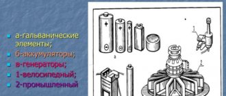
In order for electrons to begin to move in a conductor (current flows through a section of the circuit), they need to create conditions. To do this, there must be an excess of electrons at the beginning of the chain section, and a deficiency at the end. To create such conditions, voltage sources are used - accumulators, batteries, power plants.
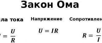
Ohm's law for a closed circuit
If an external circuit with resistance R is connected to the power source, current will flow in the circuit taking into account the internal resistance of the source:
I – Current strength in the circuit. Electromotive force (EMF) is the magnitude of the power source voltage independent of the external circuit (without load). Characterized by the potential energy of the source.
r – Internal resistance of the power supply. For electromotive force, the external resistance R and internal r are connected in series, which means the magnitude of the current in the circuit is determined by the value of the emf and the sum of the resistances: I =/(R+r) .
The voltage at the terminals of the external circuit will be determined based on the current and resistance R by the relationship that has already been discussed above: U = IR.
Voltage U, when connecting a load R, will always be less than the EMF by the value of the product I*r, which is called the voltage drop across the internal resistance of the power source. We encounter this phenomenon quite often when we see partially discharged batteries or accumulators in operation. As the discharge progresses, their internal resistance increases, therefore, the voltage drop inside the source increases, which means the external voltage U = – I*r decreases. The lower the current and internal resistance of the source, the closer in value its EMF and voltage at its terminals U.
If the current in the circuit is zero, therefore = U. The circuit is open, the emf of the source is equal to the voltage at its terminals. In cases where the internal resistance of the source can be neglected (r ≈ 0), the voltage at the source terminals will be equal to the EMF (≈ U) regardless of the external circuit resistance R. Such a power source is called a voltage source.
Formulas
Electric current parameters are always interconnected. For example, a change in the load value is reflected in the indicators of other quantities. Moreover, these changes are subject to the corresponding laws, which are expressed through formulas. Therefore, in practice, the corresponding formulas are often used to find the current strength.
Through charge and time
Let us recall the definition (Fig. 1): electricity is the amount of charge driven by the forces of an electric field that overcomes the conventional plane of a conductor, called the cross-section of the conductor, per unit time.
Rice. 1. Definition of current strength
Thus, if the electric charge passed through a conductor in a certain time is known, then it is not difficult to find the value of this charge passed per unit time, that is: I = q/t
Through power and voltage
The passport of an electrical appliance usually indicates its rated power and the parameters of the electrical network for which it is intended to work. Having this data at your disposal, you can calculate the current using the formula: I = P/U .
This expression follows from the formula for calculating power: P = IU .
Through voltage or power and resistance
The strength of electricity in a section of a circuit is determined by Ohm's law. To do this, you need to know the following parameters: resistance and voltage in this area. Then I = U/R . If the load power is known, then it can be expressed through the square of the current multiplied by the resistance of the section: P = I2R , from where
For a complete circuit, this value is calculated according to Ohm’s law, but taking into account the parameters of the power source.
Through EMF, internal resistance and load R
Using Ohm's law adapted for the complete circuit, you can calculate the maximum current using the formula I = ε / (R+r′) if the parameters are known:
- external resistance of conductors (R);
- EMF of the power source (ε);
- internal resistance of a source with EMF (r′).
Note! Real power supplies have internal resistance. Since in an electrical circuit, the current indicator may decrease due to an increase in the resistance of the power source or as a result of a drop in EMF. It is because of the increase in internal resistance that the battery runs out and the EMF of the batteries weakens.
Joule-Lenz law
It would seem that calculating the current strength based on the amount of heat released as a result of heating the conductor has no practical application. However, it is not. Let's look at this with an example.
Suppose you need to find the current strength during operation of the electric kettle. To do this, bring 1 kg of water to a boil and record the time in seconds. Let's assume the initial temperature was 10 ºC. Then Q = Cm(τ – τ0) = 4200 J/kg × 1 kg (100 – 10) = 378,000 J.
Rice. 2. Joule-Lenz law
From the Joule-Lenz law (image in Fig. 2) the formula follows:
By measuring the resistance of an electrical appliance and substituting the values into the formula, we obtain the amount of current consumed.
Ohm's law for alternating current
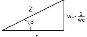
If there is inductance or capacitance in an AC circuit, its reactance must be taken into account. In this case, the entry for Ohm's Law will look like: I = U/Z
Here Z is the total (complex) resistance of the circuit - impedance. It includes active R and reactive X components. Reactance depends on the ratings of the reactive elements, on the frequency and shape of the current in the circuit. You can learn more about complex resistance on the impedance page.
Taking into account the phase shift φ created by reactive elements, Ohm's Law is usually written in complex form for sinusoidal alternating current.
What does Ohm's law sound like for a section of a circuit?
If we talk about the official formulation, then Ohm’s law can be stated as follows:
Current strength has a direct relationship with voltage and an inverse relationship with resistance. This statement is true for a section of a circuit with some specific and stable resistance.
The formula for this dependence is in the figure. Here I is the current, U is the voltage, R is the resistance.
Ohm's law formula
- The higher the voltage, the higher the current.
- The greater the resistance, the less current.
It is not so easy to imagine the meaning of this expression. After all, electricity cannot be seen. We only know approximately what it is. Let's try to understand the meaning of this law with the help of analogies.
Nonlinear elements and circuits
Ohm's law is not a fundamental law of nature and can be applied in limited cases, for example, for most conductors. It cannot be used to calculate voltage and current in semiconductor or vacuum devices, where this dependence is not proportional and can only be determined using the current-voltage characteristic (volt-ampere characteristic).
This category of elements includes all semiconductor devices (diodes, transistors, zener diodes, thyristors, varicaps, etc.) and vacuum tubes. Such elements and the circuits in which they are used are called nonlinear.
Voltage, Current and Resistance
An electrical circuit is formed when a conductive path is created that allows electrical charge to travel continuously. This continuous movement of electric charge through the conductors of a circuit is called current, and is often spoken of as a “flow,” like the flow of liquid through a hollow pipe.
The force that causes charge carriers to “flow” through a circuit is called voltage. Voltage is a special measure of potential energy that is always relative between two points. When we talk about a certain amount of voltage present in a circuit, we are talking about the measurement of the potential energy to move charge carriers from one specific point in that circuit to another specific point. Without mentioning two specific points, the term "tension" has no meaning.
Current generally passes through conductors with some degree of friction or resistance to movement. This opposition to movement is more correctly called resistance. The amount of current in the circuit depends on the amount of voltage and the amount of resistance in the circuit that prevents the passage of current. Like voltage, resistance is a quantity measured between two points. For this reason, voltage and resistance values are often specified as "between" two points in a circuit.
Coulomb and electric charge
One of the basic units of electrical measurement that is often taught early in electronics courses but not often used subsequently is the coulomb, a unit of electrical charge proportional to the number of electrons in an unbalanced state. One coulomb of charge corresponds to 6,250,000,000,000,000,000 electrons. The symbol for the amount of electric charge is the capital letter "Q", and the unit of coulombs is denoted "C". The unit of current, ampere, is equal to 1 coulomb of charge passing through a given point in a circuit in 1 second. In this sense, current is the speed at which an electric charge moves through a conductor.
As stated earlier, voltage is a measure of the potential energy per unit of charge available to stimulate the flow of current from one point to another. Before we can define exactly what a "volt" is, we must understand how to measure this quantity, which we call "potential energy."
The common metric unit for measuring energy of any kind is the joule, which is equal to the amount of work done by a force of 1 newton when moving 1 meter (in the same direction). In these scientific terms, 1 volt is equal to 1 joule of electrical potential energy per (divided by) 1 coulomb of charge. Thus, a 9-volt battery releases 9 joules of energy for every coulomb of charge passing through the circuit.
These units and symbols for electrical quantities will become very important when we begin to explore the relationships between them in circuits.
Basic parameters of direct current
Definition:
Direct current is an electric current that does not change in magnitude or direction over time.
The main parameters of electric current are:
- Current strength. Denoted as I. The unit of measurement is A (Ampere).
- Voltage. Denoted as U. The unit of measurement is V (Volt).
- Resistance. Denoted as R. The unit of measurement is Ohm.
Current strength
The current strength shows how much charge q passes through the cross section of the conductor in 1 second:
I=qt..=ΔqΔt..=Nqet.
N is the number of electrons, qe=1.6·10−19 C is the electron charge, t is time (s).
Charge passing through a conductor in time t at a current strength equal to I:
q=It
Example No. 1. The current source was connected to two plates immersed in a solution of table salt. The current in the circuit is 0.2 A. How much charge passes between the plates in the bath in 2 minutes?
2 minutes = 120 seconds
q=It=0.2·120=24 (Cl)
Charge passing in time ∆t with a uniform change in current from I1 to I2:
Δq=I1+I22..Δt
Current strength and speed of electrons:
I=nqeSv
n - (m–3) - concentration, S (m2) - cross-sectional area of the conductor, v - electron speed.
Attention!
Electrons move along the wires at a speed equal to fractions of mm/s. But the electric field propagates at the speed of light: c = 3∙108 m/s.
Resistance
The resistance of metals characterizes the inhibitory effect of positive ions of the crystal lattice on the movement of free electrons:
R=ρlS..
ρ - resistivity, showing what resistance a conductor with a length of 1 m and a cross-sectional area of 1 m2, made of a certain material, has. l is the length of the conductor (m), S is its cross-sectional area.
Example No. 2. Copper wire has an electrical resistance of 6 ohms. What is the electrical resistance of a copper wire that is 2 times the length and 3 times the cross-sectional area?
Resistance of the first and second conductor, respectively:
R1=ρlS..
R2=ρ2l3S..
Let's divide the electrical resistance of the second conductor by the resistance of the first:
R2R1..=ρ2l3S..÷ρlS..=ρ2l3S..·Sρl..=23..
Hence the resistance of the second conductor is:
R2=23..R1
Voltage
Voltage characterizes the work of the electric field to move a positive charge:
U=Aq.
Example No. 3. When moving a charge in the first conductor, the electric field does 20 J of work. In the second conductor, when moving the same charge, the electric field does 40 J of work. Determine the ratio U1/U2 of the voltages at the ends of the first and second conductors.
U1U2..=A1q..÷A2q..=A1q..·qA2..=A1A2..=2040..=12..
Ohm's law formula
Ohm's main discovery was that the amount of electric current flowing through a metal conductor in a circuit, at any given temperature, is directly proportional to the voltage applied to it. Ohm expressed his discovery in the form of a simple equation describing the relationship between voltage, current and resistance:
[E=IR]
In this algebraic expression, voltage (E) equals current (I) times resistance (R). Using algebra, we can transform this equation into two other variants, solving it for I and R respectively:
Simple calculation examples
Household AC network
Example No. 1. Checking the heating element.
The washing machine has a built-in tubular electric heater 1.25 kW at 220 volts. It is necessary to check its serviceability by measuring the resistance. Based on power, we calculate current and resistance.
I = 1250 / 220 = 5.68 A; R = 220 / 5.68 = 38.7 Ohms.
We check the resistance calculation using a current and voltage calculator. The data matched. You can begin electrical measurements.
Example No. 2. Checking motor resistance
Let's say that we bought a 1.6 kilowatt washing vacuum cleaner for cleaning premises. We are interested in its current consumption and the resistance of the electric motor in operating condition. We count the current:
I = 1600 / 220 = 7.3 A.
We enter into the columns of the calculator a voltage of 220 volts and a current of 7.3 amperes. Let's start the calculation. We will automatically receive the data:
- motor resistance - 30.1 Ohm;
- power 1600 watts.
DC circuits
Let's calculate the filament resistance of a 55-watt halogen light bulb installed in a 12-volt car headlight.
We count the current:
I = 55 / 12 = 4.6 A.
We enter 12 volts and 4.6 amperes into the calculator. It calculates:
- resistance 2.6 ohms.
- power 5 watts.
Here I would like to draw your attention to the fact that if you measure the resistance in a cold state with a multimeter, it will be significantly lower.
This property of metals makes it possible to create simple and relatively cheap incandescent lamps without the complex ballasts required for LED and fluorescent lamps.
In other words: a change in the resistance of tungsten when heated to a red-hot state limits the increase in current through it. But when the metal is cold, an inrush of current occurs. It can cause the thread to burn out.
To extend the service life of such light bulbs, a gradual, smooth supply of voltage from zero to the nominal value is used.
As simple but reliable devices for cars, a current limiting relay circuit operating in steps is often used.
When the switch SA is turned on, the resistance of the resistor R limits the inrush of current through the cold filament. When it warms up, due to a change in the voltage drop across the HL1 lamp, the electromagnet with the relay winding KL1 will put its contact on hold.
It will bypass the resistor, which will render it unusable. The rated current of the circuit will flow through the filament.
Analyzing simple circuits using Ohm's law
Let's see how these formulas work to help us analyze simple circuits:
Figure 1 – Example of a simple circuit
In the above circuit, there is only one voltage source (the battery on the left) and only one current resistance source (the lamp on the right). This makes it very easy to apply Ohm's law. If we know the values of any two of the three quantities (voltage, current, and resistance) in this circuit, we can use Ohm's law to determine the third.
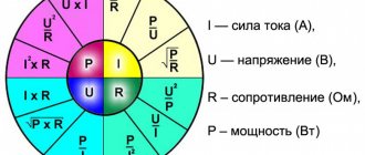
Rules for using the calculator
In everyday life, we are usually interested in four interrelated characteristics of electricity:
- voltage;
- current;
- resistance;
- or power.
If you know two quantities included in Ohm’s law (U, R, I), then enter them in the appropriate lines, and the remaining parameter and power will be calculated automatically.
Be careful to avoid mistakes.
All values must be filled out in the same dimension : amperes, volts, ohms, watts without using fractional or multiplicity symbols.
A visual table will help you navigate to them.
Ohm's Law Triangle Method
Ohm's Law is a very simple and useful tool for analyzing electrical circuits. It is used so often in the study of electricity and electronics that the student must memorize it. If you are not very good at working with formulas, then for memorizing it there is a simple trick that helps you use it for any quantity, knowing the other two. First, arrange the letters E, I and R in a triangle like this:
Figure 5 – Ohm's law triangle
If you know E and I and want to define R, just remove R from the picture and see what's left:
Figure 6 - Ohm's law for determining R
If you know E and R and want to define I, remove I and see what's left:
Figure 7 - Ohm's law for determining I
Finally, if you know I and R and want to define E, remove E and see what's left:
Figure 8 - Ohm's law for determining E
Ultimately, you'll have to learn how to work with formulas to study electricity and electronics seriously, but this tip can make it easier to remember your first calculations. If you're comfortable working with formulas, all you have to do is commit E = IR to memory and retrieve the other two formulas when you need them!
What does parallel and serial connection give?
Theoretical knowledge is good, but how to apply it in practice? Elements of any type can be connected in parallel or in series. But we considered only the simplest formulas describing linear elements. Linear elements are resistances, which are also called “resistors”. So here's how you can use what you've learned:
- If there is no large resistor available, but there are several smaller ones, the required resistance can be obtained by connecting several resistors in series. As you can see, this is a useful technique.
- To extend the life of the batteries, they can be connected in parallel. In this case, according to Ohm’s law, the voltage will remain the same (you can verify this by measuring the voltage with a multimeter). And the “lifetime” of a dual battery will be significantly longer than that of two elements that replace each other. Just note: only power supplies with the same potential can be connected in parallel. That is, you cannot connect dead and new batteries. If you do connect, the battery that has a higher charge will tend to charge the less charged one. As a result, their total charge will drop to a low value.
Practical application of Ohm's law: you can create power supplies with the desired voltage and current
In general, these are the most common uses for these compounds.
Parallel and serial connection
In electrics, elements are connected either in series - one after the other, or in parallel - this is when several inputs are connected to one point, and outputs from the same elements are connected to another.
Ohm's law for parallel and series connections
Parallel connection
A parallel connection is when the beginnings of the conductors/elements converge at one point, and their ends are connected at another. We will try to explain the laws that are valid for compounds of this type. Let's start with the current. A current of some magnitude is supplied to the point of connection of the elements. It separates, flowing through all conductors. From here we conclude that the total current in the section is equal to the sum of the current on each of the elements: I = I1 + I2 + I3.
Now regarding the voltage. If voltage is the work done to move a charge, then the work required to move one charge will be the same on any element. That is, the voltage on each parallel-connected element will be the same. U = U1=U2=U3. It’s not as fun and visual as in the case of explaining Ohm’s law for a section of a circuit, but you can understand it.
For resistance, everything is a little more complicated. Let's introduce the concept of conductivity. This is a characteristic that shows how easy or difficult it is for a charge to pass through this conductor. It is clear that the lower the resistance, the easier it will be for current to pass. Therefore, conductivity - G - is calculated as the reciprocal of resistance. In the formula it looks like this: G = 1/R.
Laws for parallel connection
Why did we talk about conductivity? Because the total conductivity of a section with a parallel connection of elements is equal to the sum of the conductivity for each of the sections. G = G1 + G2 + G3 - easy to understand. How easy it is for current to cross this node of parallel elements depends on the conductivity of each element. So it turns out that they need to be folded.
Now we can move on to resistance. Since conductivity is the reciprocal of resistance, we can obtain the following formula: 1/R = 1/R1 + 1/R2 + 1/R3.
Voltage loss
| Figure 3. Voltage loss along an electrical circuit |
Figure 3 shows an electrical circuit consisting of a battery, resistance r and long connecting wires that have their own specific resistance.
As can be seen from Figure 3, the voltmeter connected to the battery terminals shows 2 V. Already in the middle of the line, the voltmeter shows only 1.9 V, and near resistance r the voltage is only 1.8 V. This decrease in voltage along the circuit between individual points of this circuit is called voltage loss (drop).
Voltage loss along an electrical circuit occurs because part of the applied voltage is spent to overcome the resistance of the circuit. In this case, the voltage loss in a section of the circuit will be greater, the greater the current and the greater the resistance of this section of the circuit. From Ohm's law for a section of a circuit it follows that the voltage loss in volts in a section of the circuit is equal to the current in amperes flowing through this section multiplied by the resistance in ohms of the same section:
U = I × r.
Example 4. From a generator whose terminal voltage is 115 V, electrical energy is transmitted to an electric motor through wires whose resistance is 0.1 Ohm. Determine the voltage at the motor terminals if it consumes a current of 50 A.
Obviously, the voltage at the motor terminals will be less than at the generator terminals, since there will be a voltage loss in the line. Using the formula, we determine that the voltage loss is equal to:
U = I × r = 50 × 0.1 = 5 V.
If the voltage loss in the line is 5 V, then the voltage of the electric motor will be 115 - 5 = 110 V.
Example 5. A generator produces a voltage of 240 V. Electricity is transmitted through a line of two copper wires 350 m long, with a cross-section of 10 mm², to an electric motor consuming a current of 15 A. It is necessary to find out the voltage at the motor terminals.
The voltage at the engine terminals will be less than the generator voltage by the amount of voltage loss in the line. Line voltage loss U = I × r.
Since the resistance r of the wires is unknown, we determine it using the formula:
where ρ is the resistivity of copper (Table 1, in the article “Electrical resistance and conductivity”); the length l is 700 m, since the current has to go from the generator to the engine and from there back to the generator.
Substituting r into the formula, we get:
U = I × r = 15 × 1.22 = 18.3 V
Therefore, the voltage at the motor terminals will be 240 - 18.3 = 221.7 V
Example 6. Determine the cross-section of aluminum wires that must be used to supply electrical energy to a motor operating at a voltage of 120 V and a current of 20 A. Energy will be supplied to the engine from a 127 V generator along a line 150 m long.
We find the permissible voltage loss:
127 – 120 = 7 V.
The resistance of the line wires should be equal to:
From the formula
Let's determine the wire cross-section:
where ρ is the resistivity of aluminum (Table 1, in the article “Electrical resistance and conductivity”).
Using the reference book, select the available cross-section of 25 mm². If the same line is made with copper wire, then its cross-section will be equal to:
where ρ is the resistivity of copper (Table 1, in the article “Electrical resistance and conductivity”).
We choose a section of 16 mm².
Let us also note that sometimes it is necessary to deliberately achieve a voltage loss in order to reduce the magnitude of the applied voltage.
Example 7. For stable burning of an electric arc, a current of 10 A at a voltage of 40 V is required. Determine the amount of additional resistance that must be connected in series with the arc installation in order to power it from a network with a voltage of 120 V.
The voltage loss in the additional resistance will be:
120 – 40 = 80 V.
Knowing the voltage loss in the additional resistance and the current flowing through it, you can use Ohm’s law for a section of the circuit to determine the value of this resistance:
Practical use
Actually, this law can be applied to any part of the chain. An example is shown in the figure.
We apply the law to any part of the chain.
Using such a plan, you can calculate all the necessary characteristics for an unbranched section. Let's look at more detailed examples.
Finding the current strength
Let's now consider a more specific example, let's say there is a need to find out the current flowing through an incandescent lamp. Conditions:
- Voltage – 220 V;
- R filament – 500 Ohm.
The solution to the problem will look like this: 220V/500Ohm=0.44 A.
Let's consider another problem with the following conditions:
- R=0.2 MOhm;
- U=400 V.
In this case, first of all, you will need to perform the conversion: 0.2 MOhm = 200000 Ohm, after which you can begin to solve: 400 V/200000 Ohm = 0.002 A (2 mA). Calculating voltage To solve, we will also use Ohm's law. So the task:
- R=20 kOhm;
- I=10 mA.
Let's transform the source data:
- 20 kOhm = 20000 Ohm;
- 10 mA=0.01 A.
Solution: 20000 Ohm x 0.01 A = 200 V.
Don't forget to convert the values, since quite often the current can be indicated in milliamps.
Resistance
Despite the fact that the general form of the method for calculating the parameter “R” resembles finding the value “I”, there are fundamental differences between these options. If the current can vary depending on two other parameters, then R (in practice) has a constant value. That is, at its core, it is represented as an unchanging constant.
If the same current (I) passes through two different sections, while the applied voltage (U) differs, then, based on the law we are considering, we can confidently say that where the low voltage “R” will be the smallest. Let's consider the case when there are different currents and the same voltage in unconnected areas. According to Ohm's law, a large current will be characteristic of a small parameter "R".
Let's look at a few examples
Let's say there is a circuit to which the voltage U=50 V is applied, and the consumed current I=100 mA. To find the missing parameter, you should use 50 V / 0.1 A (100 mA), in the end the solution will be 500 Ohms.
The current-voltage characteristic allows you to clearly demonstrate the proportional (linear) dependence of the law. The figure below is a graph for a section with a resistance equal to one ohm (almost like a mathematical representation of Ohm's law).
Image of the current-voltage characteristic, where R=1 Ohm
Illustration of current-voltage characteristics
The vertical axis of the graph displays the current I (A), the horizontal axis displays the voltage U(V). The graph itself is presented in the form of a straight line, which clearly displays the dependence on the resistance, which remains unchanged. For example, at 12 V and 12 A, “R” will be equal to one ohm (12 V/12 A).
Please note that the current-voltage characteristic shown only shows positive values. This indicates that the circuit is designed to allow current to flow in one direction. Where the opposite direction is allowed, the graph will continue to negative values.
Note that equipment whose current-voltage characteristic is displayed as a straight line is called linear. The same term is used to refer to other parameters.
In addition to linear equipment, there are various devices whose “R” parameter can change depending on the current or applied voltage. In this case, Ohm's law cannot be used to calculate the dependence. Equipment of this type is called nonlinear; accordingly, its current-voltage characteristics will not be displayed as straight lines.