DIY drill repair
- breakdown of motor parts (stator, armature) - wear of the brushes or their burning - breakdown of the regulator and reverse switch - wear of the support bearings - poor clamping in the tool chuck.
Some spare parts (switch, rotor, stator, brushes, bearings, etc.) for more popular models are bought here (but it’s better to buy through an online store, because in a regular store of this network you will like the price higher).
Replacing brushes
. The most common type of breakdown is wear of the motor brushes, which can be replaced yourself at home. Sometimes, brushes can be replaced without disassembling the drill body. For some models, it is enough to unscrew the plugs from the installation windows and install new brushes. For other models, replacement requires disassembling the housing; in this case, you must carefully remove the brush holders and remove the worn brushes from them.
Brushes are sold at all normal power tool stores, and often an extra pair of brushes is included with a new electric drill.
Don't wait for the brushes to wear down to their minimum size. This risks increasing the gap between the brush and the collector plates. As a result, increased sparking occurs, the collector plates become very hot and may move away from the base of the collector, which will lead to the need to replace the armature.
You can determine the need to replace brushes by increased sparking, which can be seen in the ventilation slots of the housing. The second way to determine this is the random jerking of the drill during operation.
Power cord
. The cord is checked with an ohmmeter, one probe is connected to the contact of the power plug, the other to the core of the cord. Lack of resistance indicates a break. In this case, repairing the drill comes down to replacing the power cord.
Electric motor diagnostics
. In second place, in terms of the number of drill breakdowns, can be placed the malfunction of engine components and, most often, the armature. Failure of an armature or stator occurs for two reasons. improper operation and poor-quality coil wire. World-famous manufacturers use expensive coil wire with double insulation with heat-resistant varnish, which significantly increases the reliability of engines. Accordingly, in cheap models the quality of insulation of the winding wire leaves much to be desired. Improper operation comes down to frequent overloading of the drill or prolonged operation without breaks to cool the engine. Repairing a drill with your own hands by rewinding the armature or stator, in this case, is impossible without special tools. Only complete replacement of the element (exclusively experienced repairmen will be able to rewind the armature or stator with their own hands).
To replace the rotor or stator, it is necessary to disassemble the housing, disconnect the wires, brushes, remove the drive gear if necessary, and remove the entire motor along with the support bearings. Replace the faulty element and install the engine in place.
An armature malfunction can be determined by a characteristic smell, an increase in sparking, and the sparks have a circular motion in the direction of movement of the armature. Pronounced burnt windings can be seen upon visual inspection. But if the engine power has dropped, but there are no signs described above, then you should resort to the help of measuring instruments. ohmmeter and megohmmeter.
Features of the asynchronous motor of the angle grinder
Almost all electrical appliances used in everyday life use an asynchronous electric motor. An important advantage of this type of motor is that when the load on it changes, the speed does not change. This means that if, for example, you cut stone for a long time and without stopping with a household grinder, there will be no noticeable external signs of engine overload. The disk rotation speed will be constant, the sound will be monophonic. Only the temperature will change, but this may not be noticed if your hands are wearing gloves.
If you are not careful, an advantage can turn into a disadvantage. Asynchronous motors are very sensitive to overheating; a significant increase in operating temperature entails melting of the insulation on the rotor windings. At first, the motor will work intermittently, and then - when an interturn short circuit occurs - the motor will stop completely. If you overheat the grinder's engine several times, it is most likely that the anchor will melt. In addition, the high temperature causes the contacts connecting the wires of the primary winding to the collector to become unsoldered, which leads to an interruption in the supply of electric current.
Features of the operation of a commutator motor
Universal models can be powered by both alternating and direct current. The advantage has significantly extended these units to domestic use. They are installed in various power tools, including grinders, screwdrivers, sewing and washing machines.
The windings of both components, namely the stator and the rotor, are made in series connection. Current is supplied to the last element performing rotation through special brushes. They come into contact with the commutator plates connected to the ends of the rotor coils.
The reversing effect occurs by changing the polarity of the inclusion of the stator and rotor in the power supply, and the speed is by varying the volume of current generated in the windings.
Flaws:
- a lot of noise - washing machines are proof. Modern washing machines are equipped with special parts that reduce noise;
- significant price;
- difficult control.
Machines used in everyday life are distinguished by mechanical switching with field coils (CB). The latter can be independent, parallel, or sequential. Mixed types of parts are often used. CDs equipped with permanent magnets do not have the disadvantage of high cost and management. They are easy to control, and to change the direction of rotation, just change the polarity.
How to determine if an angle grinder's armature is faulty
Signs of a broken armature angle grinder are: increased sparking of the brushes on the motor commutator, vibration of the motor at low speeds, rotation of the working shaft in different directions. If such symptoms are present, you should stop using the tool - this is dangerous. Suspicions can be easily verified using simple tests.
Visual inspection from outside
Troubleshooting should begin with a visual inspection of the angle grinder:
- Carry out a general inspection of the instrument.
- Pay attention to the integrity of the power cord and the presence of voltage in the outlet.
- Using a voltage indicator, make sure that current is flowing to the motor commutator and the start button.
Read also: How to rivet a blind rivet without a riveter
Inspection of the device from the inside
If everything is in order with the power supply, but the angle grinder does not work, you will have to open the case to gain access to the motor. As a rule, disassembly is not difficult. But you need to follow simple rules that will help you avoid troubles during reassembly:
- Be sure to disconnect the device from the mains before disassembling.
- Remove the working disk and protective cover from the spindle.
- Open the case in a well-lit place, on a clean table surface.
- Remember the location of all parts and assemblies before disassembling. It is recommended to sketch or photograph the internal structure of the device.
- Place screws and fastening screws in a separate place so that they do not get lost.
It is best to inspect the engine under bright lighting so that all small parts are clearly visible. The armature should rotate freely around its axis; properly functioning bearings should not make any sound during operation. There should be no traces of melted wiring on the armature, the circuit windings should be intact, without breaks. You can smell the rotor. When there is an interturn short circuit, the insulating varnish burns and emits a persistent specific odor. But such a diagnosis requires some experience.
Continuity testing of circuits with a tester
If a visual inspection does not give clear results, it is recommended to continue the examination using a multimeter. Having set the mode switch to the ohmmeter position (200 Ohm range), you need to “ring” two adjacent armature lamellas with two probes. If the resistance on all turns is the same, this means that the windings are working properly. If on some pairs the tester shows a different resistance or an open circuit, there is a malfunction in this coil.
A wire break can occur between the winding and the core. You should carefully examine the junction of the coils with the collector lamellas in the lower part of the armature, and visually check the soldering of the contacts.
Checking contacts with a light bulb
If you don’t have a tester, you can get out of the situation using a simple 12-volt light bulb. The power can be any, optimally 30–40 W. The voltage from the 12 volt battery must be applied to the plug of the angle grinder by inserting a light bulb into the gap in one wire. If the armature is working properly, if you rotate the spindle by hand, the light should light without changing brightness. If the heat changes, this is a sure sign of an interturn short circuit.
If the light does not light, this may indicate the following:
- The brushes may become stuck in the non-working position. The retaining spring has worked.
- There has been a break in the supply circuit.
- There is a short circuit or break in the stator winding.
There are other diagnostic methods, but they require more sophisticated equipment, which is not usually used at home. An experienced technician will determine the breakdown with a high degree of accuracy using a “punch” or a simple transformer with a cut toroidal core and one primary winding.
In what cases can you save an anchor and restore it yourself?
If damage to the armature is determined with guaranteed accuracy, the part must be removed from the electric motor. Disassembling the motor must be done with special care, after removing the brushes and disconnecting the power terminals. The rotor is removed along with the support bearings and the motor cooling impeller; they form a single whole with it.
If most of the wiring in the armature is damaged and the balancing is disrupted as a result of overheating, it is better to replace it entirely. An imbalance is indicated by increased vibration and an uneven hum when the mechanism operates.
How to rewind an anchor - step-by-step instructions
If the balancing of the armature is not disturbed, and the problem is only in damaged windings, then such an armature can be restored independently by rewinding the coils. Rewinding a rotor at home requires a lot of patience and accuracy.
The technician must have skills in working with a soldering iron and instruments for diagnosing electrical circuits. If you are unsure of your abilities, it is better to take the engine to a workshop for repairs or replace the entire armature yourself.
To rewind the anchor yourself you will need:
- wire for a new winding. A copper core with a diameter exactly matching the old conductor is used;
- dielectric paper for insulating the winding from the core;
- varnish for filling coils;
- soldering iron with tin-lead solder and rosin.
Before rewinding, it is important to count the number of turns of wire in the winding and wind the same amount of new conductor onto the coils.
The rewinding process consists of the following steps:
- Dismantling old windings. They must be carefully removed without damaging the metal body of the armature. If any burrs or damage are found on the body, they must be smoothed out with a file or sanded with emery. Sometimes, to completely clean the body of slag, craftsmen prefer to burn it with a torch.
- Preparing the collector for connecting a new wire. There is no need to remove the manifold. You should inspect the lamellas and measure the resistance of the contacts in relation to the housing with a megger or multimeter. It should be no more than 0.25 MOhm.
- Removing old wiring on the manifold. Carefully remove the remaining wires and cut grooves in the contacts. In the future, the ends of the coil wires will be inserted into the grooves.
- Installation of sleeves for anchors. The sleeves are made of dielectric material 0.3 mm thick, for example, electrical cardboard. Cut a certain number of sleeves and insert them into the grooves of the cleaned anchor.
- Rewinding reels. The end of the new conductor is soldered to the end of the lamella and wound in successive circular movements, counterclockwise. This laying is called “laying to the right.” Winding Repeat for all coils. Near the collector, tie the wires together with a thick thread of cotton fabric (it is prohibited to use nylon, as it melts when heated).
- Checking the winding quality. After laying all the windings, check with a multimeter for the absence of interturn short circuits and possible breaks.
- Finishing processing. Treat the finished coil with varnish or epoxy resin to secure the winding. In factory conditions, the impregnation is dried in special ovens. You can do this at home in the oven. As an option, use quick-drying varnishes for impregnation, applying the coating in several layers.
Read also: DC motor 220V
Replacing the anchor yourself at home
Practice shows that if you decide to replace the armature of an angle grinder, then it is best to change it together with the support bearings and the engine cooling impeller.
To replace you will need:
- New angle grinder anchor. Must match your model. Interchange with other models is not permitted.
- Screwdrivers, wrenches.
- A soft brush and cloth for wiping the mechanism.
How to remove an anchor
Replacing the anchor begins with disassembling the angle grinder. The following steps are performed:
- Use a screwdriver to unscrew the brush units on both sides. The brushes are removed.
Video: replacing bearings on an angle grinder
How to put an anchor in place
To install a new angle grinder anchor in place, you should take a new part, and then assemble the tool in the reverse order. The sequence of actions is as follows:
- A fixation disk is installed on the armature shaft.
- The bearing is installed using the pressing method.
- The small gear is fitted and secured with a retaining ring.
- The anchor is inserted into the gearbox housing, and the docking holes are aligned.
- The gearbox mounting bolts are tightened.
- The anchor with the gearbox is inserted into the body of the angle grinder and fixed.
- The brushes are deposited in their places and closed with lids.
After completing these steps, the grinder is ready for work. The anchor has been replaced.
Video: how to check an angle grinder
An ancient Sufi wisdom says: “A smart person is one who is able to come out of a difficult situation with dignity. But the one who does not find himself in such a situation is wise.” By following the rules for operating household appliances and preventing the motor from overheating, you can avoid breakdowns and troubles in the operation of the angle grinder. Keeping and storing the tool clean and dry will prevent its mechanisms from contamination and oxidation of current-carrying elements. Timely maintenance of the tool is guaranteed to eliminate unpleasant surprises during operation.
In many household devices and home-made structures, low-power electric machines are used as a drive. Despite the high reliability of electric motors, their failure for a number of reasons is not uncommon. Given the relatively high cost of these devices, it is more practical to repair them rather than replace them. We suggest considering the possibility of rewinding electric motors at home.
Diagnostics
Before starting repairs, you should diagnose the failed angle grinder . This will allow you to determine the true reason why there were interruptions in the operation of the power tool and repair it at minimal cost. The electrical part of the angle grinder, which includes the rotor, is diagnosed according to certain rules using available instruments. Information on how to check the rotor for serviceability can be obtained from the link “Checking the continuity of the armature of an angle grinder with your own hands.”
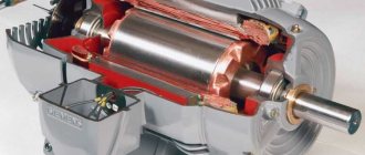
Features of repairing an asynchronous machine
Engine problems of any type can be mechanical or electrical in nature. In the first case, strong vibration and characteristic noise may indicate a malfunction; as a rule, this indicates problems with the bearing (usually in the end cover). If the malfunction is not corrected in time, the shaft may jam, which will inevitably lead to failure of the stator windings. In this case, the thermal protection of the circuit breaker may not have time to operate.
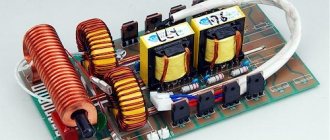
“Burnt” wires of the stator winding
Based on practice, in 90% of failures of asynchronous machines, problems arise with the stator winding (break, interturn short circuit, short circuit to the frame). In this case, the short-circuited armature, as a rule, remains in working condition. Therefore, even if the damage is mechanical, it is necessary to check the electrical part.
Laying diagram, winding Interskol 230, Makita 9558HN or 9558BN and other models
The order of winding the rotor windings depends on the number of slots in the rotor core and the commutator lamellas. The parameters that determine the location of the winding wire on the rotor include winding direction and pitch . The rotation of the spindle shaft (right or left) is precisely related to the choice of which direction the wire is laid. When performing rotor repairs, it is necessary to record the above data of the burnt winding.
Important : visually identify the topmost coil and start unwinding the end from it in order to determine the layout of the winding wire. Maintaining the old pattern is a determining factor in successful anchor repair.
The number of turns and the diameter of the wire are fixed after removing the front part of the failed winding, which will allow you to carefully remove the complete bundle of wire located in the groove.
Most of the used grinders, regardless of the model (Interskol, Makita and others), are structurally made with 24 slats and a core with 12 grooves. The winding pitch is chosen to be 6.
12 grooves and 24 slats
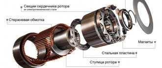
Rotor for INTERSKOL USHM-2300M, HAMMER. Photo 220Volt
The rotor winding with such design parameters is performed as follows.
- The direction of the winding is set (usually clockwise when viewed from the commutator side).
- Insulation made of electrical cardboard and other similar material is installed in the cleaned grooves . The winding wire is soldered to lamella No. 1 in accordance with the old installation scheme.
- The wire is placed in groove No. 1 opposite the lamella indicated by the first number and, according to the winding pitch, is directed into groove No. 6 and returning back. The number of such layings corresponds to the size of the winding turns.
- A circuit with 12 grooves and 24 lamellas is built after soldering the middle of the winding to lamella No. 2 and continuing to wind the winding wire into the same groove. The required number of turns is maintained and soldering is carried out to lamella No. 3. This is how the first complete reel is obtained.
- Next, winding is carried out in slots No. 2 and No. 7 , soldering the middle of the winding to lamella No. 4 and the end of the winding to lamella No. 5.
- By winding the coils using the above method, the last of which ends on lamella No. 1, all 12 grooves and 24 lamellas will be involved in the laying pattern.
Winding check
In most cases, the problem can be detected by its appearance and characteristic odor (see Figure 1). If the fault cannot be determined empirically, we proceed to diagnostics, which begins with a continuity test. If one is found, the engine is disassembled (this process will be described separately) and the connections are thoroughly inspected. When no defect is detected, a break can be established in one of the coils, which requires rewinding.
If the continuity test does not show a break, you should proceed to measuring the winding resistance, taking into account the following nuances:
- the insulation resistance of the coils to the housing should tend to infinity;
- for a three-phase drive, the windings must show the same resistance;
- For single-phase machines, the resistance of the starting coils exceeds the readings of the working windings.
In addition, it should be taken into account that the resistance of the stator coils is quite low, so to measure it it makes no sense to use devices with a low accuracy class, such as most multimeters. You can correct the situation by assembling a simple circuit using a potentiometer with the addition of an additional power source, for example a car battery.
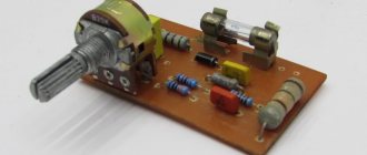
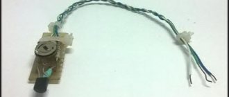
Circuit for measuring winding resistance
The measurement procedure is as follows:
- The drive coil is connected to the circuit presented above.
- The potentiometer sets the current to 1 A.
- The coil resistance is calculated using the following formula: , where RK and UPIT were described in Figure 2. R is the resistance of the potentiometer, and is the voltage drop across the measured coil (shown by a voltmeter in the diagram).
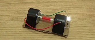
It is also worth talking about a technique that allows you to determine the location of the interturn short circuit. This is done as follows:
The stator, freed from the rotor, is connected through a transformer to a reduced power supply, having previously placed a steel ball on it (for example, from a bearing). If the coils are working, the ball will move cyclically along the inner surface without stopping. If there is an interturn short circuit, it will “stick” to this place.
What is needed to rewind a variable commutator motor with your own hands?
Before you start rewinding, you need to prepare the following list of materials and tools:
- radio multimeter - a device that measures the current and conductivity of devices. If it is absent, you can use any voltage indicator: a megger, a 12 V light bulb with a power of up to 40 W;
- new winding of the collector rotor - in this case, the diameter of the core must be identical to that of the old winding;
- radio engineering soldering iron;
- dielectric cardboard – thickness up to 0.3 mm inclusive;
- construction varnish. But it is acceptable to use epoxy resin;
- skein of cotton threads;
- sandpaper for better preparation of the material.
But in order to ensure that winding the collector unit - the motor - does not take additional time, you first need to determine the problem that caused the installation to malfunction.
Checking engine performance
The first stage is disassembling the power plant. When an interturn short circuit occurs, a corresponding smell appears. It is caused by melting of the coating. If none were found, then the armature lamellas should be checked. To do this, use a multimeter. It needs to be switched to ohmmeter operating mode, and the measuring range should be set to 200 ohms. Next, use probes to ring the structure of the armature mechanism; changing the resistance means breaking the inductor.
Nuance: The light bulb will play the role of an ohmmeter. It is connected plus/minus to the motor terminals, and is placed directly in the gap. The shaft rotates by hand, blinking of the lamp indicates an interturn short circuit. When the light bulb does not light, then there is an open circuit, a complete lack of resistance in the lamella.
It is worth considering that the resistance of the stator coils is insignificant, and therefore to measure indicators it is necessary to use instruments with a high accuracy class. They are able to detect the slightest fluctuations in parameters. As a rule, devices based on a potentiometer and an additional power source are used.
Measurements are carried out as follows:
- the motor coil is connected to a circuit with a potentiometer;
- the device delivers a current of one ampere;
- the calculation is carried out using the formula, where Rk is the resistance of the stator coil, Upit is the voltage of the additional power source, and R is the resistance of the potentiometer, equal to the voltage drop of the coil (voltmeter symbol).
Replacing a worn winding with a new one will avoid engine burnout. This also helps to extend the service life. Re-winding is recommended to be carried out at least once every 2 years.
Algorithm for determining where an interturn short circuit (IC) occurred. The technology is as follows:
- the stator is disconnected from the element that is in rotation (RE);
- connects to a reduced power source - carried out by adding a transformer;
- a steel ball is placed on the latter;
- efficient coils provoke the movement of the ball along the inner surface in a continuous mode. The MF will cause the bearing to stick.
The above tips will help you pinpoint the problem as accurately as possible. But there are situations when the use of specialized metrological installations is required - it is advisable if it is necessary to diagnose the performance of large AC units. The machines differ not only in the type of application, but also in the working environment of interaction, and the electrical winding circuits are different. Therefore, aspects of repair vary.
Features of repair of commutator drives
This type of electric machine is more likely to experience mechanical failures. For example, brushes worn out or commutator contacts clogged. In such situations, repairs come down to cleaning the contact mechanism or replacing graphite brushes.
Read also: Laying signal tape over the cable
Testing the electrical part comes down to checking the resistance of the armature winding. In this case, the probes of the device are applied to two adjacent contacts (lamellas) of the collector, after taking readings, measurements are taken further in a circle.
Checking the armature winding of a commutator motor
The displayed resistance should be approximately the same (taking into account the instrument error). If a serious deviation is observed, then this indicates that there is an interturn short circuit or open circuit, therefore, rewinding is necessary.
Typical classifications of power plants and specific repairs
For domestic use, it is important to use DC commutator units (CA) and brushless asynchronous AC machines. Synchronous installations are used extremely rarely in everyday life.
The high frequency of spacecraft breakdowns is due to the design features - the presence of a commutator-brush unit (CBU). The latter wears out or its contacts become clogged. Repair involves cleaning the mechanism and replacing brushes. Checking the electrical part of the commutator motor - testing the resistance of the armature winding. The parameters must be, plus/minus, the same for all brushes, taking into account errors.
Reference data is a way to determine the personal performance of the motor. Perhaps these or other parameters are the correct characteristics showing the serviceability of the technical unit. Special reference materials indicate:
- nominal technical characteristics: power, voltage, current consumption, number of revolutions;
- number of armature slot wires;
- conductor diameter;
- diameters of the external/internal stators of the unit.
The above aspects will help in monitoring the functionality of power machines.
Motor winding data
This is a reference data, so the most reliable way to obtain this information is to consult the appropriate sources. This data can also be provided in the product passport.
You can find advice online that recommends manually counting the turns and measuring the diameter of the wire when rewinding. It's a waste of time. It is much easier and more reliable to find all the necessary information using the engine markings, which will indicate the following parameters:
- rated operating characteristics (voltage, power, current consumption, speed, etc.);
- number of wires for one slot;
- Ø wire (as a rule, insulation is not taken into account in this indicator);
- information on the outer and inner diameter of the stator;
- number of grooves;
- with what step the winding is performed;
- rotor dimensions, etc.
Below is a fragment of a table with winding data for electric machines of type 5A.
Example of a table with winding data
Step-by-step instructions for rewinding an electric motor with your own hands
It is necessary to immediately warn that without special equipment and operating skills, rewinding reels will most likely be a useless task. On the other hand, negative experience is also experience. Understanding the complexity of a process is the best explanation of its cost.
The first stage is dismantling
We present an algorithm of actions for asynchronous machines, it is as follows:
- Disconnect the drive from the network (380 or 220 V).
- We remove the electric motor from the structure where it was installed.
- Remove the rear cooling fan shroud.
- We dismantle the impeller.
- We unscrew the fastening of the end covers, and then remove them. It is advisable to start from the front part; after dismantling it, the rotor will easily “come out” from the rear cover.
- We take out the rotor.
This process can be greatly simplified if you use a special device - a puller. With its help, it is easy to free the motor shaft from a pulley or gear, and also remove the end covers.
Puller for dismantling
We will not provide instructions for disassembling a commutator motor, since it is not particularly different. The structure of an electric machine of this type can be found on our website.
Stage two - removing the winding
The sequence of actions is as follows:
- Using a knife, remove the bandage fasteners and insulating coating from the wire connections. Some instructions recommend recording the wiring diagram, for example, by taking a photograph. There is no particular point in doing this, since this is reference information and finding it out by engine brand is not a problem.
- Using a chisel, knock off the tops of the wires from each end of the stator.
- We release the grooves using a punch of the appropriate diameter.
- We clean the stator from dirt, soot, and impregnation varnish.
Stator freed from winding
At this stage, we recommend stopping, picking up the case and taking it to specialists. Independent dismantling will reduce the cost of restoration work. As mentioned above, without special equipment it is quite difficult to rewind reels efficiently. To understand the complexity of the process, we will describe its technology, which will make the choice easier.
Stator rewinding (final phase)
The process consists of the following steps:
- Installation of insulators in each groove (sleeving).
- The thickness of the material and its characteristics are selected from the reference book.
- Winding data is determined by motor brand.
- A special machine is used to wind the required number of turns of loose coils. You can find photos and parameters of homemade manual machines on the Internet, but the quality of their work is quite questionable.
Bulk Winding Machine - The coil groups are placed in the grooves, after which they are tied and connected. These processes are quite complex and are performed manually.
- Impregnation is carried out. To do this, the body is heated to a temperature of 45°C - 55°C and completely immersed in a container with impregnating varnish. It makes no sense to varnish the wires, since in this case there will still be voids.
- After impregnation, the body is placed in a special chamber, where drying is carried out at a temperature of 130-135°C.
- Final testing of the coils with an ohmmeter.
- Assembly and test run (if only the body, but also other parts and fasteners were transferred for repair).
If only the body was submitted for restoration, we recommend checking the coils before turning on the motor.
Rewinding the armature
The process of replacing the winding of a commutator motor is somewhat similar, with the exception of small nuances associated with the design features. For example, the armature is sent for rewinding, not the housing, provided that the problem does not arise with the excitation coils. In addition, there are the following differences:
- For winding, a special machine with a more complex configuration is used.
- Grooving, balancing of the armature (in the final part of the process), as well as its cleaning and grinding are required.
- The manifold is cut using a special milling machine.
The above processes require special equipment; without it, rewinding electric motors is a waste of time.