Circuits and equipment may be designed to operate at constant or variable frequency. Operating at a frequency other than specified may result in malfunction.
For example, an AC motor designed to operate at 60 Hz runs slower below 60 Hz or faster above 60 Hz. For AC motors, any change in frequency results in a proportional change in motor speed. A five percent reduction in frequency results in a five percent reduction in engine speed.
Some digital multimeters provide additional frequency measurement modes:
- Frequency meter mode: Measures the frequency of AC signals. This mode can be used to measure frequency when troubleshooting electrical and electronic equipment.
- MIN/MAX Logging Mode: Allows you to record frequency measurements over a specified period. Voltage, current and resistance measurements can be recorded in the same way.
- Auto-ranging mode: Automatically selects the frequency measurement range. If the frequency of the measured voltage is outside the measurement range, the digital multimeter will not be able to display an accurate measurement result. For frequency measurement ranges, see the instruction manual.
Direct and alternating current
From a physics course we know that electric current is the directed movement of electrons.
With direct current, the polarity of charged particles is constant. Therefore, all devices designed to operate from it always have polarity markings for correct connection to the network. Otherwise, the device simply will not work and may also fail.
Alternating current is safer in this regard. Since its polarity is constantly changing, it does not have a detrimental effect on connected electrical appliances. Appliance plugs and AC outlets do not have polarity markings, so you can safely plug them into the network without worrying about the correct position of the contacts.
But the main advantage of alternating current is the great ability to regulate the network voltage using transformers. That is why alternating current has become much more widespread throughout the world than direct current.
Frequency Measurement Guidelines
In some circuits, accurate frequency measurement is impossible due to fairly strong distortion. Example. AC variable frequency drives (VFDs) can distort the frequency.
To obtain accurate readings when testing the VFD, it is recommended to use the low pass filter function when measuring AC voltage () ac V (). On meters without the function, move the control to the DC voltage measurement position, then press the Hz frequency measurement button again to measure the frequency in this mode. If the device allows you to measure individual frequencies, you can compensate for noise when changing the range.
Reference: Digital Multimeter Principles by Glen A. Mazur, American Technical Publishers.
Choose the right multimeter
Why is AC frequency important?
Alternating current is widely used in household and industrial electrical networks. For the normal operation of any devices and equipment, it is extremely important that the frequency of the current is constant. If it fluctuates by more than 1%, the efficiency of any machines and mechanisms connected to the network, or household appliances, significantly decreases.
In industrial production, a sharp change in the frequency of the current used can lead to manufacturing defects and even equipment breakdown.
There is a frequency standard for electric current:
- 50 Hz – Russia, countries of the former USSR, Europe, the Baltic states, North Korea, Australia;
- 60 Hz – USA, Canada, Taiwan, South Korea, Cuba, Costa Rica and others.
But, for example, in Japan both frequencies are used. In the western regions of the country, the standard frequency is 60 Hz, and in the eastern regions - 50 Hz.
content .. 31 32 37 ..Frequency measurement methods and instruments used
Measurement of the basic physical quantity - time and its derivative - frequency, as well as reproduction and storage of units; their measurements form the basis of most measurement tasks. The basis of time-frequency equipment is a group of frequency standards, including hydrogen, rubidium, cesium and quartz standards, which store the unit of time - the second and the unit of frequency - the hertz.
Devices for measuring frequency, called frequency meters, are divided into resonant 42, electronic counting 43, heterodyne 44, etc. Frequency can be measured using different devices and methods. The industry produces dial frequency meters (43-1, 43-7, etc.), which allow you to read the frequency directly on the scale of the dial device used in it in the range from 10 Hz to 500 kHz. The deflection of the instrument needle depends on the average value of the charge or discharge current of the standard capacitor, recharged by the voltage of the measured frequency. Since the current in the circuit depends linearly on the voltage, such frequency meters have a uniform scale and have a relatively high input resistance.
Rice. 43. Functional diagram of a heterodyne frequency meter
To measure high frequencies and microwaves, methods are used to compare the measured frequency with the known frequency of natural oscillations in a resonant system. Let's look at these methods.
The heterodyne method is based on comparing the studied oscillations fx with the oscillations of a calibrated high-precision generator (heterodyne) fet using a mixer. In Fig. Figure 43 shows a functional diagram of a heterodyne frequency meter (wave meter), consisting of a local oscillator G, a mixer C and an output device VP (indicator), in which the oscillation frequency is compared using the beat method.
The measurement principle is as follows. The mixer block is supplied with a highly stable frequency oscillation fet from the local oscillator and a frequency oscillation fx. From the output of the mixer, the oscillation of the difference beat frequency fbeat is fed to the output device, calibrated in the appropriate units of measurement (frequencies or wavelengths). Despite the simplicity of the device, heterodyne frequency meters allow you to measure frequencies in the range of 30-3000 MHz with high accuracy.
The resonant frequency measurement method is based on the phenomenon of electrical resonance. Wavemeters consist of a high-quality circuit, a tuning mechanism and an indicator.
Depending on the range of measured frequencies, the oscillatory circuit of the frequency meter can be made of a high-quality LC circuit with lumped constants, or in the form of a coaxial line segment, or in the form of a cavity resonator.
The functional diagram of the resonant frequency meter is shown in Fig. LKS circuit is tuned to resonance at the measured frequency
Knowing the inductance
LK
and capacitance Sk, it is easy to calculate the measured frequency.
The presence of resonance in the LKCb
registers
based on the maximum indicator reading. Typically, a resonant frequency meter has a set of replaceable LK coils,
allowing to cover the frequency range from several hundred kilohertz to several tens of megahertz.
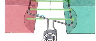
Ultrahigh frequency resonant frequency meters consist of coaxial and volumetric resonators. A section of a coaxial line, which is an oscillatory circuit, is connected to the source of oscillations (generator) and the detector by communication loops (Fig. 45). The circuit is tuned to resonance by changing the length I
internal conductor of the coaxial line. If a quarter wave of the measured vibration fits within the length of a line segment, resonance occurs. The moment of tuning into resonance is noted by the maximum deviation of the indicator needle connected to the detector circuit. Measuring the wavelength under study consists of finding two adjacent resonances in the line and determining the distance between them; it is equal to half the wavelength of the vibration being studied. Resonance wavemeters can measure wavelengths from a few centimeters to several decimeters.
The domestic industry produces a large range of frequency meters for measurements in the microwave range: for example, resonant coaxial frequency meters for frequencies from 40 to 10700 MHz (Ch2-2A and 42-37) and waveguide frequency meters for frequencies from 8 to 16.6 GHz (42-33 and 42 -31). The types of frequency meters and the frequency range they measure are shown in Fig. 46.
To carry out automatic measurement of frequencies in the range up to 10 GHz, a resonant waveguide panoramic frequency meter 42-55 is designed, which allows automatic measurement of several frequencies emitted by CB4 generators simultaneously using the device indicator. He's wide
used for testing and repairing generators in laboratory and production conditions. The frequency meter is made entirely on semiconductor devices, the measurement error is 0.5%, the sensitivity is 5-10~3 mW. Dimensions of the device are 480X255X480 mm, weight 28 kg.
For laboratory frequency measurements, electronic frequency counters are used, which provide measurement results in digital form.
The operation of these devices is based on the conversion of the measured sinusoidal voltage into short rectangular pulses corresponding to the measured frequency. These pulses are recorded by a counter.
For example, in 1 s the counter registers 1 • 106 pulses, which means that the measured frequency will be equal to 1 MHz. Such chatometers facilitate the measurement process over a wide range
lah frequencies (from several hertz to hundreds of megahertz), repetition period and pulse duration. They can also be used as sources of quartz frequencies, sensors of calibrated time intervals, etc.
Electronic frequency counters (universal ChZ-47A, 43-49 and simplified 43-44, 43-45, 43-46) carry out programmable measurement of the frequency of radio signals from fractions of a hertz to CB4 ranges with an error of ±5-10-9 and time intervals from 1 to 104 µs with an error of ±0.1 µs. They provide measurement results in a code that provides mathematical calculations, statistical processing and recording them in digital and analog forms.
content .. 31 32 37 ..
How to measure frequency with a multimeter?
In ordinary life, it is not so often necessary to measure the frequency of electric current, since it is maintained centrally in the network. Deviations, if any, are less than 1%.
You can determine the frequency of the current produced by any device using a special frequency meter. But such devices are rarely found in a home craftsman’s kit. They are mainly used by professionals. But nowadays almost everyone has a digital multimeter.
Some (not all) multimeter models are equipped with an AC frequency measurement feature. If it exists, then it will be easy to find out this parameter.
The procedure is as follows:
- The probes are connected to the appropriate sockets according to the instructions.
- The mode switch is set to measure the frequency of alternating current.
- To begin with, you can measure the frequency in the 220 V network. It is supported by the electricity supplier and is equal to 50 Hz. The frequency is measured with a multimeter by connecting the probes of the device to the contacts of the socket. If the result differs slightly from the standard frequency, this should be taken into account as an instrument error. And make corrections for it during the next measurements.
- Next, you can measure the frequency parameter of the device that interests you.
Thus, the multimeter allows you to determine with sufficient accuracy the frequency of the current in the network or at the output of electrical generators, converters, and filtering devices.
Now you know how to measure frequency with a multimeter. We wish you safe and accurate measurements!
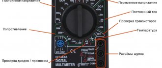
Digital multimeters with frequency symbol on regulator
- Turn the control to the Hz position.
- This symbol on the regulator is often combined with a symbol for one or more functions.
- Some meters use an auxiliary function to measure frequency by pressing a button and moving the rotary switch to ac (alternating current) or dc (direct current).
- First, insert the black test lead into the “COM” connector.
- Then insert the red wire into the "V Ω" connector.
- Once the measurement is complete, disconnect the wires in reverse order: red first, then black.
- Connect the black test lead first, then the red test lead.
- Once the measurement is complete, disconnect the wires in reverse order: red first, then black.
- Read the measurement result on the screen.
- Hz should appear to the right of the reading.
Resonant reed switches
Resonant reed switches typically operate at lower frequencies and are therefore rarely used in RF applications. However, their low frequencies make them suitable for tuning motors and other devices that use applied AC power. Because of their simple mechanical operation, resonant reed meters are less accurate than deflection meters, but are rugged enough to be used for field measurements.
Reed meters simply consist of a series of metal reeds tuned to different frequencies. When AC power is applied to the meter, the reed closest in frequency to the signal will vibrate more than the others, causing an audible signal at that frequency. This is shown in the image below. Since the 120 VAC supply voltage is properly tuned to 60 Hz, the center reed at 60 Hz vibrates more than the others.
Selecting a microcontroller
Microchip offers three new series of AVR microcontrollers:
- ATtiny 0-, 1- and 2-;
- ATmega 0;
- AVR DA- and DB-.
From a peripheral standpoint they are the same, so I could choose, for example, the ATtiny414, ATmega4809 or AVR128DA28, all of which have a TCD0 and are capable of using an external 32.768KHz crystal for timing.
I tested the first version of the circuit with the AVR128DA28, but for the final version I still chose the ATtiny414, because it was made in a more compact package, and I did not need additional inputs/outputs.
In the end, it turned out that when using the AVR128DA28 the events worked, but after switching to the ATtiny414 they stopped. It turned out that the problem was the difference in terminology for earlier processors. Here I want to thank AVR Freaks user kabasan for helping me figure this out. If you want to learn more about using an event system, I recommend starting with the AVR DA- or DB- series, which use more logical terminology.
Note.
The ATtiny 1 series, ATtiny414, released in 2022, should not be confused with the older ATtiny441, which appeared in 2014 as an expanded version of the even older ATtiny44.
Scheme
Here is a diagram of a 100 MHz frequency counter, the layout of which corresponds to the breadboard diagram:
100 MHz frequency meter circuit based on ATtiny414.
An OLED 128×32 I2C module with an SSD1306 driver is used as a display. For the prototype, I took an Adafruit display, although any analogue from AliExpress would be fine. The 33kOhm resistor and 0.1uF capacitor ensure that the display is reset correctly when power is first applied, although they may not be needed.
A 32.768 kHz crystal with an accuracy of 20 ppm and a capacitive load of 12.5 pF serves as a resonator. To calculate the capacitor values, I used the formula C = 2(CL – CS), where CL represents a capacitive load of 12.5pF and CS is a parasitic capacitance that probably reaches 5pF on a breadboard, giving C = 15pF. On a printed circuit board, its value will probably be 2.5 pF.
The processor was an ATtiny414 in a 14-pin SOIC package, which I installed on a switchboard - Adafruit has a suitable option. The project can also be implemented on the ATtiny814 or ATtiny1614 with more memory, but not on the ATtiny404, since it does not support an external RTC crystal.
Accuracy
To test this project, I needed to find a way to generate accurate signals up to 100 MHz, but I don't have such a generator.
The accuracy of my previous project, Programmable Signal Generator, is only 1.1%, which is clearly not enough for this case, besides, its upper limit is only 68 MHz. In this regard, I bought a Si5351A clock generator breakout board from Adafruit, which can be programmed via I2C to generate signals from 8kHz to 160MHz (there is also an option for a similar board on Banggood). I managed it through Jason Milldrum's excellent Si5351 library running on Arduino Uno.
The accuracy of the frequency counter primarily depends on the accuracy of the crystal used to generate the 1Hz sampled signal. I used a cylindrical crystal with a stated accuracy of 20ppm. Sounds good until you figure out that with a 100MHz input signal this is equivalent to ±2000Hz. In practice, its accuracy as a whole turned out to be 5-10 times higher than stated.
Using Timer/Counter TCD0
I thought about using TCD0 just casually.
This is a 12-bit device, but, unlike most of its analogues, it works asynchronously, that is, independently of the processor clock cycles. TCD0 is primarily intended for signal generation, such as motor control, and I'm not even familiar with many of its capabilities. However, it seemed to me that with its help it is quite possible to capture the value of a counter operating under the control of a real-time clock.
Through experience, I found out that TCD0 can be clocked at a frequency of more than 100 MHz, which would allow me to build a very simple frequency meter with the range I needed without a divider.
Using the Event System
I could use the RTC to generate an interrupt every second and then grab the counter value from TCD0 through the interrupt routine.
However, the latest AVR processors provide an Event System that allows you to do this more efficiently. It is possible to generate an internal signal from the RTC and use it to directly activate the capture. The advantage here is that calling the interrupt service does not require unnecessary processing, resulting in a response that is returned almost instantly.
Deviation meters
There are two main types of deflection meters: moving coil meters and ratio meters. Moving coil meters are electrically resonant circuits that consist of two coils tuned to different frequencies and connected at right angles to each other. Frequencies in the middle of the range equalize the currents in the two coils and allow the needle or pointer to indicate the midpoint of the scale.
Sell frequency meters
Frequency changes create an imbalance between these currents, causing the coils and the needle or pointer to move. Ratio meters use two frequency inputs: a known standard and an unknown quantity. Precious metals in frequency meters are a fairly common occurrence because... This equipment cannot work without radio components.