A lighting control system based on pulse relays can no longer be called some kind of know-how.
She appeared a very long time ago. However, the widespread practice of introducing and using bistable relays, as they are also called scientifically, instead of the old time-tested pass-through switches, is becoming increasingly widespread right now.
Of course, there are more modern devices based on control via a Wi-Fi signal or connected to a PLC, but impulse switches (blocking relays) are more affordable for a wide range of ordinary users.
On average, their price ranges from 1000 - 1500 rubles per piece, depending on the manufacturer and functionality (built-in timer, central control function, etc.)
They are also more repairable. If one relay fails, only one lighting zone will stop working, and the light will not go out in the whole house, as will happen with a PLC.
Let's look at how it all works, what circuits it is connected to, and try to figure out whether it is better or worse than pass-through switches.
How to make a pulse relay?
There are quite a few types of relays, but the problem with conventional ones is that they need to be constantly supplied with energy, or voltage. What if you don’t have space or can’t afford it to save money? Is there any way to fix this? Yes, and a pulse relay can help in creating circuits in such cases. What is it, how does it work? What features of the scheme should be taken into account by those who decide to make it themselves? A conventional relay is a board that has a built-in system for receiving pulsed information signals.
Why only push-button ones?
When using pulse relays, other types of switches are used - push-button, bell or push-type.
Please note that simple single-key or two-key keyboards will not work here.
With rare exceptions, for example for the Meander RIO-2 relay. But more on that later.
Based on this fact, a signal cannot be applied to pulse relays for too long, otherwise its coil will burn out. Some manufacturers warn that the continuous signal time on their models should be no more than 1 minute.
And some children really like to play with such buttons, after which they fail.
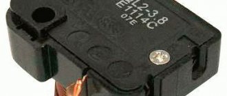
Push-button switches resemble ordinary ones in appearance, only inside their design there is a return spring, which after each press returns the key and contact to its original position.
There are also two-key buttons in one housing.
They will come in handy when you want to connect general lighting in the kitchen from one relay and at the same time illumination of the work area of the countertop.
Or in the hall - a chandelier and lighting around the perimeter, plus a separate sconce.
Many people use spring-loaded buttons for doorbells instead of special switches.
Pulse relay circuit
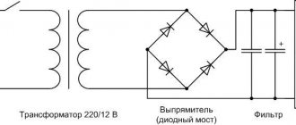
The pulse relay is based on two circuits. The first is responsible for control, the second contains the load circuit. Considering that all impulses are created exclusively due to electromagnetic fields, an important advantage should be noted - this device is silent. The elements of the second circuit also contain a part that is responsible for the relay memory. In general, if we consider existing technologies, we will notice that any low-voltage modular device has a mechanism that is responsible for storing data. Therefore, when disconnected and reconnected, the pulse relay “remembers” the last settings, information about the connection, the state of the network and the operation of the device itself. Considering the circuit, technically educated people may ask the question: why use such a device if a regular pass-through switch can be used to monitor illumination? But the fact is that even the simplest relay option offers a significant range of actions. Thanks to it, you can monitor the lighting from three or more places. And it doesn't require much effort to connect. Let's look at what types of these devices exist.
Battery insulators and decoupling relays
Battery insulators (dividers) and decoupling relays are designed to protect the battery from being discharged by an unintentional load. Both types of devices distribute current from the charging source to all batteries and isolate them from each other during discharge. This way, each battery group remains connected only to its own load.
Insulators are made from two or more diodes that act as check valves. Diodes allow current to flow from the charging source to the batteries, but do not allow current to flow between them or back to the source. The simplicity of the design comes at a price. About 0.6-0.8 volts drop across the diodes, so the voltage at the batteries is lower than at the output terminals of the generator or charger. If the losses are not compensated, the batteries will never charge to 100%
Battery isolators and decoupling relay. The insulator divides the current between the batteries. The voltage drop across the diodes is 0.6-0.8 Volts. A relay passes current from one battery to another
Both relays and diode isolators are decoupling devices that solve the same problem. However, it is better to use them in different situations. Isolators are suitable if the charging source measures the voltage across the batteries and is able to compensate for the drop across the diodes by increasing the output voltage.
It is easier to upgrade the electrical system using an isolation relay. The charger and generator will continue to work with multiple batteries in the same way as they previously worked with one. An isolation relay is the only choice for some outboard motors and inverter combinations. Motors and inverters are connected to the battery by a single cable, through which current flows in different directions while the batteries are charging and during engine starting (inverter operation). A diode insulator will prevent this from happening.
Relay type
Several popular industrial-type samples will be considered:
- Pulse electromagnetic relay. Bistable type 411. Can transmit up to 12 V.
- Bistable type 413. The device has a special circuit, thanks to which the light turns off after a certain period of time.
- Devices series 412 and 414. Combined the characteristics of the two previous types.
But please note that the samples shown, while reliable, do not represent the entire range of devices. There are many other types of relays that are used in specific applications. Thus, the devices indicated here are used when working with lighting or devices that operate on a similar principle.
Model with microcontroller
Devices with microcontrollers are very common. They are suitable for pushbutton switches. The devices are also actively used in switches. Experts recommend using only capacitive resistors for assembly. In total, the relay will require three capacitors. The rated voltage is on average 24 V. With a conductivity of 2 μ, the resistor should produce an overload of 10 A.
The modulator for relays can be used as a line type. As a rule, modifications with three outputs are produced. The bistable relay (microcontroller) is controlled by a switch. It is also worth noting that there are devices with wired stabilizers. The resistance value of the elements should not exceed 45 Ohms.
How to do it yourself?
- 12 V and 0.03 mA (ideal for use with a solar battery).
- The resulting output current will be 7 A.
- There are four switches.
When the device is in latching mode, each time a signal is received, an instantaneous pulse is generated. If it is necessary to set a timer, one usually chooses one that operates in two time ranges: up to one second, and 1-100. But if you don’t want to complicate things, the pulse relay circuit presented here may well satisfy you. In industrial designs, there is already a configuration system; in home-made devices, you will have to create it from scratch.
Source
What is a time relay (hereinafter referred to as R.V.) with a delay
A conventional relay is designed to turn on devices after receiving a signal. The time relay does not operate immediately, but after a period of time specified during its manufacture or configuration has passed. If executed with a delay, then another period is counted before turning on or off. It is also either provided during the manufacture of the device or configured (programmed).
TEST:
4 questions to test your theory
- Is it possible to use a delay relay like a regular relay?
a) You can’t, these are completely different devices.
b) Yes, for this we set the delay to zero. (loyal)
- Are relays with on-delay and off-delay different?
a) Yes, the first ones work out the delay before starting the main timer, the second ones only wait the time after the shutdown command. (loyal)
b) No.
- Is it possible to replace a relay with a turn-off delay with a relay with a turn-on delay?
a) No, these are different devices. (loyal)
b) Yes.
- Can a relay with a switch-on delay be replaced with two regular time relays?
a) Yes, if you connect them correctly. (loyal).
b) No.
Important to know - a relay with a delay in turning on and off 2 different devices
A conventional time relay turns on the device mounted after them for a period of time set during setup. That's not how latency devices work.
With switch-off delay - 1 relay operating in reverse
- The relay sends a signal to turn off the device.
- The delay time begins counting down, after the period has expired the device turns off.
If such a relay is mounted in front of a regular lamp, then it will not go out immediately after the switch is triggered, but after the delay time has passed.
With delayed start - 2 devices in one
- A signal is sent to the relay, it turns on its mechanism or electronic circuit.
- The delay time starts immediately.
- After the time has been counted, the relay turns on the connected device for the specified time.
In fact, these are two time relays connected in series.
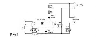
12 V bistable relay circuit
A possible connection diagram for this module looks like this:
The scheme had not been seen before, but was developed from scratch. Before starting installation in the car, of course, preliminary tests were carried out with surface-mounted assembly.
Results
A pulse relay is an alternative to pass-through switches, allowing you to save on wire/equipment and expand the ability to create complex lighting circuits.
Depending on the situation, you can choose conventional models or devices with a timer that provide a time delay before operation.
Pulse relay. Connection diagram. Lighting control from multiple locations.
Device
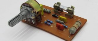
There is a wide variety of pulse relays on the market; due to technical and design differences, you can find different devices. But as an example, we will consider the simplest and most practical principle of operation for understanding (see Figure 1).
Rice. 1. Example of a pulse relay device
The simplest example of a pulse relay consists of the following elements:
- Coil - made of a copper conductor wound on a non-magnetic base, for example, a frame made of textolite, electrical cardboard, etc. Designed to create an electromagnetic field that affects magnetic elements.
- The core is made of ferromagnetic materials that interact with the magnetic field of the coil. Designed to move and perform magnetic influence.
- Relay contact system - consists of movable and fixed contacts designed to transmit a signal.
- Resistive, capacitive and signal elements are used to set the operating logic of the device and indicate the state.
- Timer – sets the time interval for the relay, but is not present in all models; it helps to significantly expand the functionality of the equipment.
Principle of operation
The principle of operation of a pulse relay is to move the contact group under the influence of the electromagnetic field of the coil that retracts the core. In this case, the device is controlled through push-button channels. One press of the button sends a short-term pulse to the control output, and the contacts go into a stable state - supplying or turning off voltage, which is why it is also called bistable (two stable states). Unlike the same contactor, such a relay is controlled by a single pulse supplied by a button or switch with self-return to its original state, hence the name pulse relay.
For example, consider the operation of a specific device model - RIO-1 (see Figure 2):
Rice. 2. Operating principle of the RIO-1 relay
This device contains two groups of contacts - power and control. Power contacts are represented by terminals 11, 14 and N, control terminals Y, Y1, Y2; it should be noted that in other modifications of pulse relays the markings and number of contacts will be different. Let's consider the purpose of each of the inputs in order:
- 11 – designed to supply power to it from the electrical network;
- 14 – used to supply phase from a pulse relay to the connected load;
- N – terminal for connecting the neutral wire from the common bus;
- Y – universal input, when a control pulse is applied to which, the relay switches to the opposite state - from on to off and back;
- Y1 – is intended exclusively for switching the pulse device to the on state, that is, if the contacts are already closed, the relay will remain in the same position and has priority over the Y input;
- Y2 – switches the pulse device to the off state, has priority over the other two outputs.
Relay control from two places
The electric potential from the phase wire (L) is transferred to terminal (2) of the button (S1), both when the button (S1) and (S2) are pressed. Inside in the diagram you can see the coil symbol which controls the relay contact when we apply voltage to terminals (A1) and (A2).
This way we can attach any number of buttons to control the light independently from different places. If you want to add an additional control from another location, simply add another button into the circuit and connect it in parallel to any other button that controls that lamp, or directly to a relay.
Varieties
A wide selection of pulse relays provides a fairly large assortment, differing in both pricing policy and functionality provided. According to the principle of operation, all models can be divided into electromechanical and electronic (Figure 4).
Figure 4. Electronic and electromechanical relay
The first option involves mechanical movement of the elements of the pulse device due to electromagnetic interaction between the coil and the core. The second type is controlled by semiconductor elements and switches without mechanically opening contacts and moving parts.
In addition, pulse relays may differ in:
- Rated load - indicates the permissible amperage that can be connected to the power contacts;
- Number of poles - can have a different number of inputs and outputs to implement certain tasks;
- Installation method - can be mounted on a DIN rail in accordance with section 1 of GOST R IEC 60715-2003, a bracket or other placement option;
- Purpose – the most popular are pulse relays for controlling lighting, protection and alarm circuits.
Also, bistable devices differ in overall dimensions, case materials, and the presence or absence of signal lamps.
Modifications with variable modulator
A bistable relay with a variable modulator is well suited for detectors of different directions. Most modifications are available with open resistors. To assemble the relay yourself, it is more advisable to use a phase expander. The modulator in the device is installed immediately behind the contacts. It should also be noted that there are modifications to wired extenders. They have a low conductivity threshold. However, they can operate on AC power. The stabilizer for the relay can be selected on a conductor basis. The rated voltage of the element must be at least 24 V.
Specifications
In accordance with clause 2.1. GOST 16121-86 parameters of pulse relays must comply with the technical specifications and standards on the basis of which they are manufactured. The most relevant for the operation of bistable switches are:
- the number of push-button switches that can be connected together with a certain type of lamp;
- limits of permissible voltage for switching;
- maximum current load permissible for switching;
- permissible number or power of light bulbs of a certain type;
- overall dimensions must correspond to passport data in accordance with clause 2.2.1 of GOST 16121-86
Fig.7. Example of overall dimensions of a pulse relay
- signal time and response delay;
- mechanical and electrical strength of structural elements;
- wear resistance by number of cycles;
- Climatic performance.
Some of this data can be found on the body of the pulse relay (see example in Figure 8), others only in the device passport.
Rice. 8. Relay characteristics
Relay and battery switch
Combined operation of the battery switch and decoupling relay.
1.Switch in ON position. The engine is running. Relay is closed. All devices are connected to their own batteries. The service battery is charged via a relay. 2.Switch in ON position. The engine is switched off. Relay is open. The load is connected to the service battery. The starting battery is isolated. An automatic charging relay in combination with a battery switch makes it easy to charge two independent batteries. The boat owner simply turns the switch to the ON position when arriving on the boat or yacht, and returns it to the OFF position when disembarking. He no longer has to worry about which batteries are charging or discharging, the relay automatically connects and disconnects them. Use Blue Sea 6011 or Blue Sea 5511 battery switches in conjunction with the relay
Application
The scope of application covers all areas where automation requires remote control of one object from several points. In everyday life and some industries, this is room lighting that can be controlled from several points. This issue is especially relevant for organizing the power supply of a “smart home”.
In automation and centralization systems on the railway network, it provides telecontrol and dispatch signaling processes. Used for signaling and transmitting operating signals.
References
To prepare the article, the following technical literature was used:
- Iglovsky I. G., Vladimirov G. V. “Handbook on low-current electrical relays” 1984
- Filipcheiko I, P., Rybin G. Ya. “Electromagnetic relays” 1968
- Gurevich V.I. "Electrical relays. Device, principle of operation and application. Engineer's Handbook" 2011
- Sivukhin D.V. “General course in physics” 1975
- Obolentsev Yu.B., Gindin E.L. “Electrical lighting of general industrial premises” 1990
Source
Relay installation and connection
Always work from the device to the batteries. First connect the cables to the relay, then install the fuse, and only then connect the cable to the battery. This sequence is safer than connecting from batteries to the device
All cables running directly from the batteries must be fused. They protect the cable from fire, which can occur when a damaged positive conductor comes into contact with the hull of a car or boat. Fuses are placed as close to the battery terminals as possible so that most of the cable is protected.
The fuse rating is chosen to be 30-50% greater than the relay rating. For example, a device rated at 100 amps will require a 130-150 amp fuse. Many relays are designed to withstand an overload of 600% of the nominal value, but withstand this current for only a few milliseconds
| Charging current | Minimum cable cross-section, mm2 | Fuse rating, A |
| 50 | 10 | 75-80 |
| 70 | 16 | 80-90 |
| 90 | 25 | 125-130 |
| 110 | 35 | 150 |
| 120 | 50 | 150-175 |
To protect the cable from batteries, fuses ANL, MRBF, MIDI / AMI are suitable for the relay. A 5 amp fuse is sufficient for the signal conductors.
Ask a question,
and get advice on outboard electric motors, batteries or chargers for a boat or yacht