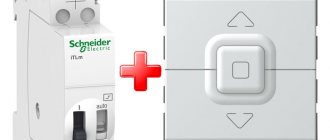
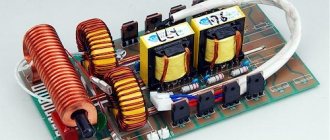
A Solid State Relay (SSR) or Solid State Relay (SSR) is an electronic device that performs the same functions as an electromechanical relay, but contains no moving parts. Commercial solid state relays use semiconductor device technologies such as thyristors and transistors.
That is, instead of moving contacts, TSRs use electronic semiconductor switches, in which the control circuits are galvanically isolated from the power switched circuits. Fortunately, now there are no problems purchasing switching field-effect transistors. Thus, to build a solid-state relay, we need a MOSFET (Metal-Oxide-Semiconductor Field-Effect Transistor) transistor, the Russian equivalent of the term is MOS transistor or insulated gate field-effect transistor, and an optocoupler. On the pages of the site there are articles devoted to transistor switches with optical isolation - “AC transistor switch”
This article discusses a key for switching alternating current. Using SMD components according to this scheme, it is possible to produce an alternating current SSR. Some of the parts are mounted on a printed circuit board, which is attached to an aluminum support. Transistors are mounted on the substrate through mica spacers. It is better to take capacitor C1 either tantalum or ceramic. Its capacity can be reduced. Another article - “Transistor switch with optical isolation”
In this circuit, bipolar transistors of different structures are used as switching transistors.
There is another circuit of a galvanically isolated switch on a mos-transistor with protection against the maximum load current. It was discussed in the article “Powerful DC switch on a field-effect transistor”
All this is good if the voltages with which SSRs implemented on MOSFETs operate allow these field-effect transistors to be controlled. But what about voltage switching, for example 3.3 volts. This voltage is clearly not enough to open the field effect transistor. We need some kind of converter capable of raising the control voltage to at least five volts. Using a classic pulse converter for relays is too cumbersome. But there are other converters - optical, for example - TLP590B .
TLP590B Datasheet Pdf
Such converters provide an output voltage of about 9 volts, which is quite enough to control MOSFETs. From the documentation for these converters it is clear that they are very low-power and capable of delivering an output current of only about 12 μA. MOS transistors have this parameter - Gate charge - Qg. Until the gate of this transistor receives the necessary charge, the transistor will not begin to open. The charging speed depends on the current that the control circuit can provide; the greater the control current, the faster the gate receives the required charge, the faster the transistor opens. The shorter the time the switching transistor will be in the active zone of the output characteristic, the less heat will be generated on it. But in our case, when the transistor does not operate in a converter, at relatively high frequencies, but as a relay, on - off, a current of 12 μA will be sufficient. The truth is, of course, it is better to choose key transistors with a low gate charge. For example.
Design and principle of operation of TTR
While most such electronics traditionally contain moving parts of contact groups, a solid-state relay has no such parts at all. Circuit switching by the device circuit is carried out according to the principle of an electronic key. And the role of electronic keys is usually played by semiconductors built into the body of the relay - power transistors, triacs, thyristors.
Before trying to make a solid-state relay yourself, it is logical to familiarize yourself with the basic design of such devices and understand the principle of their operation.
Industrial production produces solid-state relays of various configurations, designed for a variety of practical conditions. The choice of modifications is extensive
As part of a thorough study of the device, one should immediately highlight the advantageous aspects of TTP:
- switching of powerful load;
- high switching speed;
- ideal galvanic isolation;
- ability to hold high overloads for a short time.
Among mechanical structures, it is really not possible to find a relay with similar parameters. In general, the advantages of solid-state relays relative to their mechanical counterparts are expressed in an impressive list.
Two electronic devices that functionally provide circuit switching: on the left is based on a solid-state design, on the right is a traditional mechanical switching system
The operating conditions for TSR practically do not limit the use of these devices. In addition, the absence of moving mechanical parts has a beneficial effect on the service life of the devices. So there is every reason to start working on a solid-state relay - to assemble the device yourself.
However, in fairness, along with the positive aspects, it is worth noting the properties of the relay, which are characterized as disadvantages. Thus, for the operation of powerful devices, as a rule, an additional design component is required, which is designed to remove heat.
In case of switching a powerful load, solid-state relays are almost always supplemented with powerful cooling radiators. This point somewhat complicates the use of TTP
Cooling radiators for solid-state relays have overall dimensions several times greater than the dimensions of solid-state relays, which reduces the convenience and rationality of installation.
TSR devices during operation (in the closed state) give a reverse leakage current and show a nonlinear current-voltage characteristic. Not all solid-state relays can be used without restrictions in the characteristics of the switched voltages.
Design for use only in circuits powered by direct current. Typically, these devices are distinguished by their small dimensions and low switching power.
Certain types of devices are designed to switch only direct current. The introduction of solid-state relays into a circuit usually requires additional measures aimed at blocking false alarms.
Solid state relays can often be found in the general electrical panel of an apartment.
How does a solid state relay work?
The control signal (usually a low-level voltage coming, for example, from a control controller) is supplied to the LED of the optoelectronic pair present in the SSR circuit. The LED begins to emit light towards the photodiode, which in turn opens and begins to pass current.
A generalized SSR diagram that clearly shows how an electronic device functions: 1 – control voltage source; 2 – optocoupler inside the relay housing; 3 – load current source; 4 - load
The current passing through the photodiode arrives at the control electrode of the key transistor or thyristor. The key opens and closes the load circuit.
This is how the switching function of the device works. All electronics are traditionally enclosed in a monolithic housing. Actually, that’s why the device was called a solid-state relay.
You can read about how to connect a solid-state relay in this material.
Types of Solid State Switches
The entire existing range of devices can be divided into groups based on the category of the connected load, features of voltage control and switching.
Thus, there will be a total of three groups:
- Devices operating in DC circuits.
- Devices operating in alternating current circuits.
- Universal designs.
The first group is represented by devices with operating control voltage parameters of 3 – 32 volts. These are relatively small-sized electronics, equipped with LED indication, capable of functioning without interruption at temperatures of -35 / +75 ºС.
A widely used design of an electronic device for use in a single-phase electrical network. There are also other design options, but much less frequently.
The second group is devices intended for installation in alternating voltage networks. Here are the designs of TSRs for installation in AC networks, controlled by a voltage of 24 - 250 volts. There are devices capable of switching high power loads.
The third group is devices for universal use. The circuitry of this type of device supports manual configuration for use in certain conditions.
Based on the nature of the connected load, two types of AC solid-state relays should be distinguished: single-phase and three-phase. Both types are designed for switching fairly powerful loads at currents of 10 - 75 A. In this case, peak short-term current values can reach 500 A.
A widely used version for use in a three-phase electrical network. Often used as a linear regulator of powerful electric heaters (TEH)
The load switched by solid-state relays can be capacitive, resistive, or inductive circuits. The switch designs allow smooth control of, for example, heating elements, incandescent lamps, and electric motors without unnecessary noise.
Reliability of operation is quite high. But in many ways, the stability and durability of solid-state relays depends on the quality of product manufacturing. Thus, devices produced under a certain brand name “Impuls” are often noted for their short service life.
On the other hand, the products leave no reason for criticism.
12 V modifications
Bistable relay (12 volt, automotive) suitable for wired type contactors. It is often used in lighting control systems. Coils for modifications are suitable for different frequencies and diameters. If you trust specialists, then you can select resistors of the operational type with an open cover. In this case, modulators are used only on a thyristor, and the conductivity of the element will be about 3 microns.
Transceivers for relays are selected with a negative direction. The nominal voltage of devices may be greatly reduced. This happens due to an increase in the load on the capacitors. To increase the voltage parameter, tetrodes are used, which are powered by converters. Filters for them are installed with a conductivity of 10 microns.
Circuit breakers
Now let's see which fuses are responsible for what in the same mounting block. I will also give the main reasons for troubleshooting.
F1 (5 A) - license plate lighting lamps, dashboard lighting, side lights on the panel, trunk lamp, left side lights . If any of the listed lamps do not work, check this fuse, as well as the lamps themselves and their contacts. If everything is in order, check the headlight switch button.
F2 (7.5 A) - low beam in the left headlight . If both low beam headlights do not work, also check relay K4 and the lamps themselves. It could also be the light switch and its contacts.
F3 (10 A) - high beam in the left headlight . If both high beam headlights do not work, check the K5 relay, the lamps themselves and the high beam switch knob.
F4 (10 A) - front fog lamp on the right side . If both fog lights do not work, check relay 9 and the headlight bulbs themselves, as well as the switch and its contacts.
F5 (30 A) - window lift motors . If the power windows do not work, check this fuse and relay 5. In winter, check if the windows are frozen, warm them up and clear them of ice if necessary. It could also be the window lift motor, its mechanism and gears; in order to get to it, you need to remove the trim of the desired door.
F6 (15 A) - portable lamp fuse.
There may also be problems with the cigarette lighter. To check, unplug the cigarette lighter from the connector. If this fuse stops burning, then the problem is in the cigarette lighter.
F7 (20 A) - engine cooling fan, sound signal . If the cooling fan does not turn on and the engine overheats, check this fuse. Also check the operation of the fan motor by connecting it directly to the battery. It could also be the coolant temperature sensor or thermostat.
Do-it-yourself solid-state relay: diagram
Even a novice radio amateur can make a solid-state relay with his own hands. There is nothing complicated in the design of this device, but you still need to understand the circuitry, application and connection features. A solid-state relay is an element made from semiconductors. Its design contains power switches based on triacs, thyristors or transistors. These silent operating relays are a good replacement for contactors and starters. With their help, devices are connected more reliably and securely.
Simple relay circuit
In power electronics there is often a need to use a single or 3 phase solid state relay. You can make this device with your own hands according to one of the schemes presented in the article.
The advantage of solid-state relays over mechanical contactors is obvious - they have a much longer service life. And this is due to the fact that they do not have a single mechanical component, and they are the most vulnerable.
To make a solid-state relay, you can use chains consisting of a control circuit and a triac. Galvanic isolation is carried out by a triac optocoupler. The circuit uses the following elements:
- Optocoupler type MOS3083.
- Triac brand VT139-800 16A with insulated anode.
- A limiting resistor that reduces the current passing through the LED.
- LED to indicate device operation.
- A 160 Ohm resistor is connected to the control electrode of the triac.
Now let's take a closer look at the device manufacturing process.
Features of the manufacturing process
It is recommended to enclose all circuit elements in a metal case so that cooling occurs much better. For reliability, you need to fill the box with a glue gun. The main thing when working is to choose the right metal substrate to ensure the best heat dissipation. For manufacturing, formwork is used, which contains a solid-state DC relay. You can make it with your own hands from any material.
A plastic box or piece of pipe is ideal. It all depends on the size of the product. The metal backing must be placed in this formwork. Carefully fill all circuit elements and holes in the case with glue to ensure high-quality insulation. Please note that triacs usually have ambiguously defined pins, so they need to be checked in advance. To check the opening of the triac, you must use a megger. As soon as the triac opens, the resistance will change from several tens of megaohms to 1-2 kOhms.
Detector devices
A bistable relay designed for detectors is often found on the market. The devices are controlled by the controller. You can make models for detectors yourself. For this purpose, only one resistor is prepared. The conductivity of the element must be at least 12 microns at an overload of 2 A. The operating frequency of this type of relay is approximately 20 Hz. If we consider a simple modification, then the expander is installed at 13 V. The contactors are soldered behind the resistor. It should also be noted that you will need a transceiver circuit with a conductivity of about 5 microns.
If you use highly sensitive elements, there is a risk of increased voltage. In this case, it is more advisable to install switched thyristors. They are sold with and without insulators. Most often, the permissible overload level for the elements is 4 A. They operate from dipole-type converters. Contacts can only be installed in front of the modulator.
DIY simple solid state relay
A solid-state relay, which is a powerful thyristor (triac) electronic switch, is more convenient, more reliable, has a significantly longer service life and operates silently, compared to traditional electromagnetic relays. Such a key relay has no moving parts, sparking, burning, or wearing contacts. It is not difficult to make (even in makeshift conditions) such an electronic relay of any conceivable degree of protection (dust, humidity, aggressive environments). In most cases, electronic relay switches are successfully used for switching AC loads in devices and devices under construction; by upgrading or repairing old devices (using powerful electronic switches), we improve their characteristics. For example, failure of mechanical thermostats with bimetallic bending contacts used in many household appliances is a very common cause of breakdowns. By using such an electronic key, we relieve the contact group of the standard mechanical thermostat, enormously increasing its service life.
Here, the relay-electronic key is designed to control electric spiral heaters in a special low-power oven. The solid-state relay is controlled by a temperature controller with a special output. A transistor cascade is used to interface with the controller. In general, the circuit of the executive part repeats [1], differing in execution. Here, triacs in TOP-3 cases are used as keys, which made the assembly quite compact.
Schematic diagram of a solid-state relay on a triac. A VTA-41 triac and a KT315 transistor are used here. Triac optocoupler – MOS3020 (LED switching current 30 mA). Chain C1, R3 is designed to improve the dynamic characteristics of the triac, the smaller of the resistance range corresponds to the resistive load of the switch, the larger one corresponds to the inductive load. The resistor gets hot, it is better to choose a ceramic one with a power of at least 5 W. If necessary, the key can also be used for manual switching, similar to [2], in this case the transistor stage is removed, and the LED is supplied with power from a low-power network unit. This actuator circuit can also be used for controllers that are not equipped with a special (for solid-state relay) output. It is enough that the control device has a regular relay output, albeit a weak one. The normally open group of contacts of the standard relay should be connected to the LED power supply.
Aluminum cases from worn-out personal computer hard drives are used as radiators for the triac switch. They turned out to be quite convenient for such an application - there was an excellent place to mount the triac, and all the parts of the high-voltage part fit well. The size of the HDD case is standard; there are holes with threads for special short screws. In some cases, it is very convenient to use a metal case from an old system unit. The triac switch modules are mounted in their standard places in a special “basket”. It is better to design a narrow-high tower case for its horizontal position, while all radiators with keys inside will be located vertically for normal natural cooling (don’t forget about the ventilation holes). Or use airflow and temperature control.
My control unit will be three-phase, this will complicate the circuit and increase the cumbersomeness of the control unit, but it will reduce the passing currents by three times, evenly distribute the heating elements (triacs, snubber elements) and will allow the use of a three-phase rural network, albeit skewed.
What was needed for the job.
A set of tools for electrical installation, a medium-power soldering iron (40...60 W) with accessories, a multimeter, a hair dryer or a special one for working with heat pipes.
A set of tools for small plumbing work, metal scissors, an electric drill or screwdriver, a set of drills.
Materials – used HDD, required radio elements, fasteners, wire, small items
From my electrical trash, I picked up three guaranteed unnecessary hard drives, removed the controller boards and mechanical parts, and left only the powder-painted aluminum tray. In one of the HDD options, the drive motor turned out to be pressed to death, left it as is, it won’t hurt.
I marked out the mounting locations for large elements. A ceramic 10 W snubber resistor was secured with a tin clip cut from a can of condensed milk (eat, wash, dry, cut off the ends, straighten). I secured the clips with resistors with M3 screws (+ nuts, washers, stoppers).
I pressed the triacs in the chosen place with strips of non-thin PCB. The same M3 screws with everything associated, the triac was isolated from the radiator by a thin mica plate. I plopped some heat-conducting paste under the plate and under the triac.
All electrical installation was carried out using short, rigid wires - thick tinned copper wire and an insulated thermal tube. The circuit is simple, the leads of the mechanically fixed elements were enough. For a more convenient connection of the load, I made short wire leads from the legs of the triac, the control signal is connected to the terminals of the protruding optocoupler. To avoid confusion, the unused pin was bitten off.
Manufacturing recommendations
In accordance with the design features, the device circuit should be assembled not on a PCB, but using wall-mounted installation. There are quite a lot of circuit solutions , and you should choose the right one depending on various parameters, for example, switching power.
Electronic components and functionality check
As an example, consider a simple circuit.
The use of the MOS3083 optical pair makes it possible to generate a control signal, the input voltage of which is in the range of 5–24 V. To extend the life of the AL307A LED, a chain consisting of a resistance and a zener diode is introduced into the circuit. Finding all the electronic elements will not be difficult. The assembled circuit must be checked for operability.
To do this, you can not connect a voltage of 220 V to the circuit, but limit yourself to parallel connection of the tester to the control line of the triac. On the measuring device, you must first select the “mOhm” mode and apply 5-24 V power to the control voltage generation section. If the circuit was assembled correctly, the tester will show the difference in resistance in the mOhm-kOhm range.
Housing design
The base of a homemade solid-state relay will be an aluminum plate with a thickness of 3 to 5 mm. The dimensions of the plate are not of fundamental importance, and when choosing a material, it is necessary to take into account only the conditions for high-quality heat removal from the triac. It should also be remembered that the surface of the base must be flat and must first be cleaned with fine sandpaper on both sides.
The next step is to install a border plate made of plastic or thick cardboard around the perimeter. The result should be a box, which is then filled with epoxy resin. A relay circuit assembled using a hinged mounting is installed inside the housing. In this case, only a triac should be located on the aluminum plate.
To improve the heat dissipation process, you should use thermal paste, placing it over the entire contact area of the aluminum base and the semiconductor element. It should also be remembered that some triacs have an anode that is not insulated, and they are installed only through a mica substrate.
Filling with compound
To make the mixture you will need alabaster and epoxy resin without a hardener. The use of alabaster allows you to solve two problems at once - a mixture of ideal consistency is created and a sufficient amount of solution is obtained with minimal consumption of epoxy resin. During preparation, the compound is thoroughly mixed, after which you can add the hardener and mix again.
After this, the created circuit is carefully filled with the compound to the top level, leaving only part of the control LED head on the surface. When making a solid-state switch housing, you can use any solution suitable for casting. The only criterion when choosing ingredients is the lack of ability to conduct electricity.
A homemade SSR would be a good choice for connecting to a low-voltage, low-power circuit. It is not practical to assemble more powerful devices designed for high voltages. Such circuits are highly complex and it is better to buy a ready-made device.
What can be done better
After completing the implementation of the first module of my computer, I came to the conclusion that some things could be done better:
- Probably, the number of relays used in the ALU could be reduced by combining addition and subtraction modules. I think that 8 relays could be saved this way.
- When working on the next module, you need to try to drill holes more carefully. This time, some of them came out with small (and one with large) cracks.
- Experience has shown that in our city it is not very easy to make high-quality laser engraving on brass. Apparently, next time I’ll have to try using photolithography to make inscriptions.
- It is likely that redundancy will have to be used for frequently switching circuits such as a clock generator, since relays have not proven to be very reliable.
Project website: github.com/Dovgalyuk/Relay Other computers:
- Harry Porter's Relay Computer: web.cecs.pdx.edu/~harry/Relay
- Relay Computer Two: www.electronixandmore.com/projects/relaycomputertwo/index.html
- RC-3 Relay Computer: www.computerculture.org/projects/rc3
- Edmund Berkeley's Simon Relay Processor: www.cs.ubc.ca/~hilpert/e/simon/index.html
- TIM: www.northdownfarm.co.uk/rory/tim/tim-8.htm
- DUO 14 Premium: www.ostracodfiles.com/ostracod/relay.html
- Relay computer "trainer": relaysbc.sourceforge.net
- i² 8-Bit Relay Computer: isquared.weebly.com
- Kilian Leonhardt's relay computer: www.relaiscomputer.de
- Der Relaisrechner: www.schlaefendorf.de/relaisrechner/dokumentation/index.html
Advantages and disadvantages
Unlike other types of relays, solid state relays have no moving contacts. Switching of electrical circuits in this device is carried out according to the principle of an electronic key made on semiconductors. To avoid problems when creating a solid-state relay, you need to understand the operating principle of the device and its design.
However, it’s worth starting with a description of its main advantages:
- Ability to switch powerful loads.
- Switching occurs at high speed.
- High-quality galvanic isolation.
- Capable of withstanding severe overloads for a short period of time.
No mechanical relay has similar parameters. The scope of application of solid state relays (SSR) is practically unlimited. The absence of moving elements in the design significantly increases the service life of the device. However, it should be remembered that the device has not only advantages . Some properties of TTP are disadvantages. For example, during the operation of powerful devices, it becomes necessary to use an additional element to remove thermal energy.
Often the dimensions of the radiator significantly exceed the dimensions of the relay itself. In such a situation, installation of the device is somewhat difficult. When the device is closed, it experiences current leakage , which leads to the appearance of a nonlinear current-voltage characteristic. Thus, when using SSRs, you should pay attention to the characteristics of the switched voltages. Some types of devices can only operate in DC networks. When connecting a solid-state relay to a circuit, it is necessary to provide methods of protection against false alarms.
Expenses
- Relay – 6120
- LEDs – 2660
- Toggle switches – 1510
- Power supply – 2520
- Wires and other parts – 1220
- Inscription plates (materials, engraving and fasteners) – 3340
- Case materials – 4300
- Total – 21670
So far it’s 2 times cheaper than Harry’s. This does not include solder and flux, sandpaper, faulty or damaged parts, or the cost of tools I acquired while making the case.
Other modern computers using electromagnetic relays
Some of them more or less repeated Harry’s project, some only demonstrated that the creation of such a computer was possible. For example, the DUO 14 Premium, shown in the picture below, can execute a program containing up to 8 simple commands.
I wanted it to be able to calculate at least something real, and also for all its elements to be visual - it would be possible to trace the operation of the ALU, registers, instruction counter, etc. I decided to start manufacturing with an ALU. To determine the requirements for it, I roughly developed a set of instructions, and also estimated what buses and signals would be needed. The ALU has a parallel design (all bits are calculated simultaneously) and is designed for 8-bit calculations.
I immediately decided that I needed to make a subtraction module. Many other computers do not implement this module, since its work can be done using negation and addition. Thus, the ALU will perform the following operations: addition, subtraction (with and without carry), logical AND, OR, NOT, EXCLUSIVE OR, as well as right shifts (with carry or in a circle). I took the circuits for addition and logic operations from HPRC.
Another rarely seen feature is that the result of the calculation is latched into a shadow register. It is needed so that the same general purpose register can be used as both an input and an output.
Since the ALU must still operate without other computer components, therefore, to debug it, toggle switches are connected to the relay coils, supplying power to them. The results of calculations can be observed using LEDs connected to the outputs of the circuits. Regardless of the latched result, the computing units are constantly working, so the results of all operations can be observed simultaneously using indicators.
Light sensor devices
A bistable relay for sensors can be made on the basis of two high-conductivity modules. First of all, during assembly, a resistor is prepared. Its rated voltage should be 15 V. It is also worth taking care of a chain of capacitors with high capacitance. Only one thyristor is needed. Experts say that the stability of the element can be improved through the use of variable blockers.
These devices are sold with or without covers. Their operating frequency fluctuates around 40 Hz. In this case, the resistance in the circuit does not fall below 55 Ohms. Expanders are installed at the beginning of the circuit and must be located in front of the contacts. A tester can be used to check the conductivity.


