Without sockets and switches, which ensure not only uninterrupted contact between equipment and electricity, but also are responsible for safety, not a single house can be built. Therefore, the correct placement of power for lamps, televisions, microwave ovens, kettles, hair dryers, electric razors and much more is so important. If a person is not a specialist, then it is unlikely that he will independently draw a drawing with sockets and switches, but knowing their designation will be useful: it will be easier to understand the finished plan and make adjustments.
The electrician does not care where to place the boxes of electrical components, sockets and the meter, so after drawing up the diagram, he will give it to you for approval. GOST has developed a unified system for designating electrical elements. The standard provides for conventional graphic drawings in projects for easy reading and interpretation. It is worth understanding that a project is not just paper, but an official document and is drawn up according to all principles and standards.
Necessity of the scheme
An electrical wiring diagram is necessary for its safe and high-quality placement.
For the purpose of high-quality and safe placement of electrical wiring, a plan is drawn up. It looks like a drawing to scale. The document reflects the layout of the apartment, the placement points of wiring units in groups, as well as circuit diagrams.
For understanding of the drawing by all participants in repair and installation work, sockets and switches are indicated by graphic drawings according to the all-Russian and global standard.
Geometric shapes are used as graphic markers - circles, squares, rectangles, dots and lines. Their combinations reflect the types of lighting system mechanisms and the features of controlling these devices.
Symbols for other devices
In addition to switches and sockets, the wiring diagram contains other components. For example, a circuit breaker, RCD, and voltage control relay are designated as an open contact.
According to GOST, to mark a circuit breaker, a certain number of contacts connected to each other and a square on the side are used. The image indicates simultaneous activation and the presence of protection. At the input, the apartment is equipped with a two-pole circuit breaker; single-pole circuit breakers are used to stop the load.
Difavtomats and RCDs do not have icons regulated by GOST, so the drawings show the specifics of the design. RCD devices are current transformers with an executive contact relay. The differential circuit breaker has a similar assembly, but a circuit breaker is added to the components, protecting against short circuits and overloads.
The controller relay is designed to turn off equipment if the voltage rating is exceeded. It consists of a board and a contact relay. The diagram is applied to the cover of the device and transferred to the power line plan.
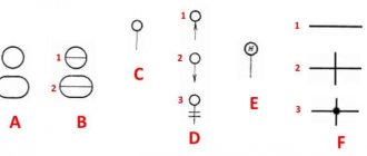
Several graphic symbols are used for backlighting and lighting devices:
- square – fluorescent light source 600x600 mm;
- rectangle – fluorescent lamp 600x300 mm;
- square with two lines – LED light source measuring 600x600 mm;
- a large “bow” with partially painted black triangles – an emergency lighting device 600x600 mm;
- a narrow “bow” with partially filled black areas on the triangles - a device for emergency lighting 600x300;
- a circle divided by an arc – a device with a high-pressure light bulb;
- a circle without two segments with 4 dashes (“slices”) and a horizontal arrow to the right – spotlight;
- a circle divided in half is a light source with contact fluorescent lamps;
- a circle with narrow areas at the top and bottom - an LED lamp of any nonlinear shape;
- circle – a lamp with a halogen or incandescent lamp;
- a circle divided into 6 segments - a chandelier;
- rectangle – linear fluorescent lamp;
- rectangle with 2 lines – linear LED lamp;
- black bow – emergency lamp.
The device icon is selected depending on its appearance and purpose.
It is not necessary to know the symbols of parts of the electrical network by heart. When understanding the icons and drawing correctly, the user will always decipher the symbols or read the footnotes.
Normative base
GOST 21.614-88
On the territory of the Russian Federation, the designation of a group or single sockets and switches on design drawings is subject to the following documents:
- GOST 21.614-88. Subsection “Images of conventional graphic electrical equipment and wiring” from the section on the system of design and construction documentation;
- GOST 21.210-2014. Electrical devices, according to the standard, can be depicted in the form of standard symbols;
- IEC 60027. A standard adopted by the International Electrotechnical Commission, according to which wiring in Russian buildings must meet international requirements.
The regulatory documentation notes the specifics of creating symbols for power lines and auxiliary devices on the working diagram.
Specifics of designations in Russian GOSTs
GOST 2.721-74 The
domestic regulatory framework, indicating what rules and methods the marking of parts of an electrical circuit is subject to, includes the following GOSTs:
- 2.755-87 - the section on symbols for contacts and switching connections determines the method of designating thermal relays, contactors, circuit breakers, switches. There is no graphical index for RCDs and automatic devices;
- 2. 721-74 - indicates which sign is used for general parts and components and secondary electrical networks;
- 2. 709-89 – the features of graphic marking of sections of the electrical circuit, special equipment, cable connection technologies and other elements are noted.
GOST 2.702-2011 stipulates the possibility of arbitrary image of nodes and the need to decipher markers.
Standards for symbols
The procedure for indicating symbols on diagrams is regulated by GOST 21.614.88. This standard was published relatively recently. The new GOST replaced the old Soviet standard. According to the new rules, the signs on the diagrams must coincide with the regulated ones.
The inclusion of other equipment in the circuit must meet the requirements of GOST 2.721.74. This document establishes standards for general use signs. The procedure for organizing the circuit of input distribution devices is also regulated by GOST 2.721.74
Designations are made in the form of graphic symbols, which are the simplest geometric objects, including squares, rectangles, circles, lines and points. In certain combinations, these graphic elements indicate certain components of electrical devices, machines and devices used in electrical engineering. In addition, the symbols represent the operating principles of the system.
Types of electrical circuits accepted in domestic practice
Conventional designation of electrical outlets on diagrams
According to the requirements of the ESKD, the diagram is a graphic document where special icons mark the structural parts of the system and the technologies for their connection. According to the accepted international classification, there are more than 10 of them. Not all are used in the Russian Federation.
Functional and structural diagrams
Structural is the simplest diagram in which the elements of the circuit are depicted in squares with explanations. This technique helps to understand the peculiarities of the system. The functional drawing contains detailed characteristics of the components and their electrical connections.
Schematic diagram
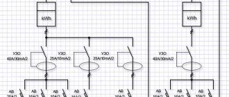
It is used for arranging distribution lines and control panels. Elements are inscribed on it without any relative position. The basic drawing is:
- single-line with power circuits - one common line is used for ground, phase and neutral;
- complete with all nodes and cores of their connections - electrical communications are drawn in an expanded and element-by-element form.
A complete schematic diagram is drawn up on several sheets.
Installation drawing
Contains a plan for the placement of lighting devices, sockets and switches, indicating the connection method. May contain additional information necessary for electrical installation work.
If it is necessary to save space on the sheet and know the markings without signatures, a combined scheme is used. It combines the above types of drawings.
Sockets for hidden electrical wiring
Concealed wiring is the most common type of home electrical network. To install it, devices are used that are built into the wall using special mounting boxes.
USEFUL INFORMATION: Floor hatches for sockets
The only difference between the designation of such rosettes and the above figure is the perpendicular, lowered from the middle of the straight segment to the center of the circle.
Specifics of the socket designation on the diagram
Electrical accessories are classified according to the degree of protection, installation method, and number of poles. These parameters explain the differences in symbols in the drawing.
Symbols of sockets for outdoor/open installation
The diagram of the fittings selected for the external installation method shows the following designations:
- pairing, grounding and unipolarity;
- pairing, absence of “ground” and unipolarity;
- single, one pole and the presence of a protection contact;
- power socket, which has 3 poles and protection.
A single-pole double socket has the shape of a semicircle with a dash in the center. The bipolar one has two lines. Two-pole grounded models for open installation are designated as a semicircle with a horizontal line protruding on both sides and a vertical dash. Three-pole devices with “ground” - a semicircle with 5 fan-shaped lines (1 in the center and 4 on the sides). Single devices are marked with one line, double ones with a double dash.
Three-pole switches, designated as a semicircle with three outer lines, are suitable for a three-phase network type.
Designations of sockets for flush/internal installation
A socket intended for hidden wiring is indicated on the diagram in the form of a semicircle intersected along a vertical line.
Modifications are installed internally:
- bipolar - a semicircle with a central vertical line extending beyond the contour of the figure;
- bipolar with a protective contact - a semicircle with a vertical line directed upward and a horizontal line protruding beyond it;
- three-pole with protective contact - a semicircle with a dash inside the center and black lines (5 pieces on top);
- double-pole double - a semicircle with a dash in the center and two thick parallel lines (reminiscent of a plug).
The horizontal ground line is the same for all models.
Marking of moisture-resistant sockets (case protection degree IP44-IP55)
For moisture-resistant switching devices, an icon in the form of a black, completely filled semicircle is intended. The picture stands for a device with a protective cover that prevents moisture from accessing the main elements. The wiring diagram in the bathroom and kitchen provides 2 types of sockets:
- waterproof with two poles - a black semicircle with a dash on top;
- waterproof with two poles and a protective contour - a black semicircle with a horizontal line and a line at the top.
Marking the degree of protection in English letters IP indicates its presence. The first number indicates the level of dust protection, the second – moisture protection.
How are blocks of a switch and socket designated?
To save space for the strobe and simplify the layout, the lighting controllers are placed in a common housing. The diagram shows the switch and socket depending on the number of elements:
- Block for hidden installation (1 switch + 1 socket) - a semicircle with a vertical line protruding upward. A T-shaped diagonal line extends from its lower part.
- Block for hidden installation (1 switch + 1 socket with grounding) - a semicircle with vertical and horizontal lines (forming a cross). From the bottom point of the figure there is a diagonal line in the shape of the letter T;
- hidden double block of switches and a grounded socket - a semicircle with a vertical and horizontal line in the form of a cross. From the common point, T-shaped lines extend diagonally to the left and right;
- a block in which there is a two-key and one-key switch, as well as a socket - a semicircle with vertical and horizontal lines forming a cross. On the left, a T-shaped diagonal line emerges from a common point. On the right is a line with a diagonal direction and two short horizontal lines that “close” it.
Due to the complexity of block diagrams, it is better to provide explanations and footnotes.
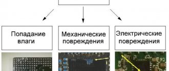
Devices with increased protection from dust and moisture
The sockets considered do not have a high level of protection against the penetration of solid objects into their housing, as well as moisture. Such products can be used in interior spaces where operating conditions exclude such effects. As for devices intended for installation outdoors or, for example, in bathrooms, according to the accepted classification, their degree of protection should be below IP44 (where the first digit corresponds to the level of protection against dust, the second - against moisture).
Such sockets are indicated on the diagram in the form of a semicircle completely shaded in black. As in the previous case, two-pole and three-pole waterproof sockets are indicated by the corresponding number of segments adjacent to the convex part of the semicircle.
Specifics of switch symbols
The generally accepted designation of a switch on an electrical network diagram is as follows:
GOST 21.210-2014 states that there is no single icon for push-button models and dimmers. In clause 4.7. The document says that you can take arbitrary values.
Sometimes the drawings indicate an automatic switch type. Its symbol can be seen from the table.
The graphic symbols that are commonly used to denote a switch are shown in table form.
Table of degrees of protection
GOST 21.614-88 contains recommendations on symbols for groups of switches:
- for surface mounting (protection from IP20 to IP23);
- for hidden wiring (protection from IP20 to IP23);
- moisture-resistant devices (protection from IP44 to IP55);
- pass-through device for two positions with protection from IP20 to IP23;
- moisture-resistant walk-through models with protection from IP44 to IP55.
GOST R-52565-2006 notes that the pole of one switch must close only one line.
Marking of single-key and two-key models on electrical circuits
To designate a switch, you must specify the number of keys. For this purpose the following symbols are used:
Three-key devices are designated as a dash with a circle and three hooks.
Socket blocks
Often, in terms of a home electrical network, it is necessary to provide for the installation of blocks that include different numbers of the most common elements - sockets and switches.
The simplest block, containing a two-pole socket and a single-key hidden switch, is depicted in the form of a semicircle, from the center of which a perpendicular is drawn, as well as a line at an angle of 45, corresponding to the single-key switch.
USEFUL INFORMATION: Using a timer socket
Blocks containing different numbers of sockets and switches are drawn on the diagram in a similar way. For example, a hidden installation unit, which includes a two-pole socket, as well as one-key and two-key switches, has the designation:
Thus, the designation of elements on an electrical diagram is carried out in such a way as to ensure the greatest ease in its preparation and reading. It is worth remembering the basic principles of constructing such circuits once, so that in the future you can easily use an apartment wiring plan of any complexity.
Underfloor heating plan
If the customer wants to install heated floors, the design project includes their plan. Namely, taking into account the location of the furniture and the layout, the exact location is indicated and the binding of the thermostat is given. Its location can be indicated both on this plan and on the switch plan. Typically, heated floors are installed in those rooms where tiles (tiles, porcelain stoneware) are provided, namely the hallway, loggia, bathroom. If the room area is large (especially in cottages), the heated floor can be located in the living room, if the “finish” coating again involves tiles, etc.
Linking plumbing equipment
A separate drawing is a plan with plumbing connections. The moment when the installation is installed in bathrooms is especially important. This drawing is important for specialists who will install all equipment.
In the next part of the articles about the procedure for developing a design project , we will describe the final and, in the opinion of GIANT GROUP customers, the most enjoyable parts of visualization. As one of our clients said: “What can be clearly understood with the eyes, and not just drawings” - wall layout, 3D visualization of the design and drawing up a list of finishing materials.
Ceiling plan
An important part of the project is the ceiling plan. Modern technologies and materials make it possible to use parameters such as color, structure and shape of the ceiling to achieve the desired goals. Plus savings, which, while maintaining the effect, but using different materials, can significantly reduce the budget for installation and materials (paints, coatings).
Also important are the drawings themselves, which indicate the type and boundaries, indicate heights, spotlights and lamps.
Once a decision has been made and the ceiling consists of several levels, separate plans can be developed for the builders with the exact dimensions of the structure.
Designations of elements of an open installation
The simplest two-pole electrical socket of open installation without a grounding contact is depicted on the electrical diagram in the form of a semicircle with a line drawn perpendicular to its convex part.
The designation of a double socket differs from the previous one in the presence of two parallel lines. The graphic symbol corresponding to a three-pole product is a semicircle, the convex part of which is adjacent to three lines converging at one point and arranged like a fan.
To designate a socket with a grounding contact, a horizontal line is added to its image, which is tangent to the top point of the semicircle.