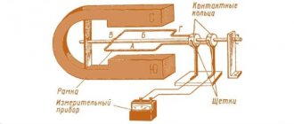
A voltage transformer will accordingly be called a step-up if the voltage at the output from the secondary winding is higher than in the primary, and a step-down if the voltage in the secondary winding is lower than in the primary. The figure below shows the operating diagram of the transformer:
Transformer circuit diagram
Red (in the figure below) indicates the primary winding, blue the secondary winding, and also shows the transformer core, assembled from special electrical steel plates. The letters U1 indicate the voltage of the primary winding. The letters I1 indicate the current of the primary winding. U2 indicates the voltage on the secondary winding, I2 indicates the current in the secondary. In a transformer, two or more windings are inductively coupled. Transformers can also be used for galvanic isolation of circuits.
Transformer operating principle
Transformer operating principle
Transformation coefficient - formula
If the transformation ratio is less than one, then the transformer is step-up, if it is more than one, then the transformer is step-down. Let's look at a small example: w1 the number of turns of the primary winding is equal to 300, w2 the number of turns of the secondary winding is 20. Divide 300 by 20, we get 15. The number is greater than one, which means the transformer is a step-down. Let's say we wound a transformer from 220 volts to a lower voltage, and now we need to calculate what the voltage will be on the secondary winding. We substitute the numbers: U2 = U1kt = 22015 = 14.66 volts. The output voltage from the secondary winding will be 14.66 volts.
Transformers on diagrams
The transformer is designated on the schematic diagrams as follows:
Transformer designation on diagrams
The following figure shows a transformer with multiple secondary windings:
Transformer with two secondary windings
The number “1” indicates the primary winding (on the left), numbers 2 and 3 indicate the secondary windings (on the right).
Determination of device currents
When determining the primary winding current, losses should be taken into account, as well as the magnetizing current of the transformer, the relative magnitude of which in low-power power transformers is very significant. The current values can be determined using the following formula:
It will be interesting➡ What is a pulse transformer and how to calculate it
where U1 and U2 are the voltages of the windings as specified;
P2 – power of the secondary winding as specified;
cos φ2 – load power factor according to the specification;
η – coefficient of performance (efficiency) of the transformer.
The choice of induction in the core rod and current density in the wires of the transformer windings - the permissible value of induction in the rod and yoke of the transformer core is determined by the selected value of the magnetizing current, power, frequency, type of transformer, number of joints in the core and the material of the latter.
You can read the article in more detail about the design of power transformers.
Welding transformers
There are special welding transformers.
The welding transformer is designed for electric arc welding; it works as a step-down transformer, reducing the voltage on the secondary winding to the required value for welding. The voltage of the secondary winding is no more than 80 Volts. Welding transformers are designed for short-term short circuits of the output of the secondary winding, in which an electric arc is formed, and the transformer does not fail, unlike a power transformer.
Varieties
The designation of transformers necessarily begins with the type of equipment. If the marking begins with the letter A, it is an autotransformer. Its absence indicates that the unit belongs to the class of power transformers.
The number of phases is required. This allows you to choose an installation operating from a household or industrial network. If the transformer is connected to a three-phase network, the marking will contain a T. Single-phase varieties have the letter O. They are used in household networks.
If the device has a split winding, it will have a P. If there is on-load voltage regulation (OLTC), the device will be marked H on the metal plate. If it is absent, we can conclude that the presented feature is absent in the device.
Power transformers
Photo high voltage transformer
Transformers from 6-10 kilovolts to 380 volts are located near consumers. Such transformers are located at transformer substations located in many courtyards. They are smaller in size, but together with HVs (load switches) that are placed in front of the transformer and input circuit breakers and feeders, they can occupy a two-story building.
Transformer 6 kilovolt
Three-phase transformers have windings that are connected differently than single-phase transformers. They can be connected into a star, a triangle and a star with the neutral removed. The following figure shows, as an example, one of the connection diagrams for the high voltage and low voltage windings of a three-phase transformer:
An example of connecting the windings of a power transformer
Transformers exist not only for voltage, but also for current. Such transformers are used to safely measure current at high voltage. Current transformers are designated in the diagrams as follows:
Current transformer diagram image
The photo below shows exactly these current transformers:
Current transformer - photo
There are also so-called autotransformers. In these transformers, the windings have not only magnetic coupling, but also electrical coupling. This is how a laboratory autotransformer (LATR) is designated in the diagrams:
Laboratory autotransformer - diagram image
LATR is used in such a way that by turning on part of the winding, using a regulator, you can obtain different output voltages. A photograph of a laboratory autotransformer can be seen below:
In electrical engineering, there are schemes for safely switching on LATR with galvanic isolation using a transformer:
Safe LATR image on the diagram
A matching transformer is used to match the resistance of different parts of the circuit. Instrument transformers are also used to measure very large or very small voltages and currents.
Application area
These devices are designed to convert the operational parameters of three-phase electrical networks and are used in the following types of power systems:
- electricity transportation and distribution systems;
- converting devices;
- electrical technological installations (welding equipment, electric furnaces, etc.);
- communication and telemechanics devices;
- automation systems;
- household electrical equipment;
- electrical measuring devices.
A suitable connection diagram is determined in accordance with the operating conditions of the device, which include network power, voltage level, and load asymmetry. The choice of connection scheme is also influenced by economic considerations.
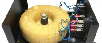
Toroidal transformers
The industry also produces so-called toroidal transformers. One of these is shown in the photo:
Photo – toroidal transformer
The advantages of such transformers compared to conventional transformers are higher efficiency, less iron sound chatter during operation, low stray field values, and smaller size and weight.
Transformer cores, depending on the design, can be different; they are made from plates of soft magnetic material; the figure below shows examples of cores:
Transformer cores - drawing
Here, in brief, is all the basic information about transformers in radio electronics; various special cases can be considered in more detail on the forum. Author AKV .
Checking the device
The belonging of a transformer to one or another connection group can be determined using a polarometer-voltmeter of the magnetoelectric system with zero in the middle of the scale and the polarity of its terminals marked.
Each group of connections corresponds to a specific table of polarometer needle deviations for the transformer under test and, after comparing it with the existing ones, a group of winding connections is established.
When the HV windings are switched on to a constant voltage of a certain polarity, an instantaneous EMF is induced in the other windings of the transformer at the moment of switching on, the magnitude and direction of which depend on the group of connections of the windings and are recorded using a polarometer.
The video below discusses in detail the operating principle of a three-phase transformer and its structure.
Reading circuits: transformers, autotransformers.
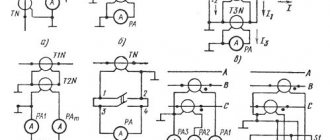
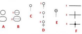
The basic designations of transformers and autotransformers on electrical diagrams include the designations of windings, housing, magnetic circuits, screen, as well as designations of types of winding connections. Let's take a closer look at all this.
Windings . In diagrams (usually in power supply diagrams), the windings are designated in the form of a circle, which is illustrated in Fig. No. 1. In all other cases, the windings are illustrated by semicircles No. 2-5 , and the number of semicircles and the direction of the conclusions is not established. And the point shown in Fig. 3, next to the winding, marks the beginning of the winding.
Nos. 13-23 , are included in them . Here, under the symbols, which consist of dashes, are explanatory diagrams.
In the figure: No. 13 – single-phase winding with two terminals. No. 14 – single-phase winding with two terminals with a neutral (middle) point removed. No. 15 – connection of the windings of two phases in an open triangle. No. 16 - three single-phase windings, each of which has two terminals. No. 17 – three-phase winding connected in a “star”. No. 18 is also a three-phase winding connected in a star with the neutral brought out. No. 19 three-phase winding connected in a triangle. No. 20 – three-phase winding, where three phases are connected in an open triangle. No. 21 – three-phase winding connected in a zigzag. No. 22 is a six-phase winding, which is connected in the form of a reverse star. No. 23 - the same as No. 22 , only with separate neutral points displayed.
Magnetic cores . In power supply diagrams, magnetic circuits may not be illustrated unless this, of course, causes difficulties and confusion in the diagrams. In all other cases, this element is depicted by designations Nos. 7-10. Here No. 7 is a ferromagnetic magnetic circuit.
( Please note: until recently, the magnetic core had a different designation: 3 - thin lines, as if representing the sheets of steel from which the magnetic core was assembled). Then the magnetic circuit began to be depicted with a bold line. Currently, the designations have the same thickness of lines indicating the magnetic core and winding.
№ 8 — ferromagnetic magnetic core with an air gap. A small air gap is needed in the case when not only alternating but also direct current passes through the winding, which, in the absence of a gap, could saturate the magnetic circuit;
№ 9 — magnetodielectric magnetic core. Such magnetic cores are used in radio communications to reduce eddy current losses. In these cores, the ferromagnetic particles are separated by a mass of insulating material.
№ 10 — a magnetic core made of non-magnetic material, for example aluminum or copper. For a non-magnetic magnetic circuit, indicate the chemical symbol of the metal. For example, the letters Cu indicate that the magnetic circuit is copper. A magnetic core made of non-magnetic material plays the same role as many short-circuited turns introduced into the magnetic field of the winding. In a non-magnetic magnetic circuit there are eddy currents, the magnetic field of which counteracts the main field, thereby reducing the inductance.
The housing of the transformer and autotransformer is usually not shown on the diagrams. If it is necessary to show that the body is attached to something, then this is illustrated by designation No. 12 . Often the transformer housing is connected to the screen.
Transformer housings also have to be shown in some relay protection schemes.
The screen is indicated by a thin dashed line number 6 . You can read more about screen designations here.
Designation No. 11 illustrates the regulator, here it shows that the assembly contains transformers with voltage regulation with the load.
Examples of transformer designations are given in the figure below.
Section “a” shows single-line - 1 and multi-line - 2 designation of a single-phase transformer with a ferromagnetic core (form I). No. 3 is an image of the same transformer in form II. Section “b” shows: No. 4 – a transformer with a ferromagnetic magnetic core, which has an air gap. No. 5 transformer with a copper (non-magnetic) magnetic core. No. 6 – transformer with a magneto-dielectric magnetic circuit. No. 7 – without magnetic circuit.
Autotransformers . A single-phase autotransformer in single-line and multi-line images is illustrated below in the figure by designations 1 and 2 , respectively. A good example of the use of these single-phase transformers is: No. 3 , reducing the network voltage from 220 volts to power an appliance (for example, a refrigerator) to 127 volts. No. 4 shows an increase in voltage from 127 to 220 V. Also in section “b” three-phase autotransformers are shown, where No. 5 shows that the windings are connected in a star, and No. 6 is a three-phase transformer with 9 terminals.
As you can see, reading diagrams is not a very difficult thing; the most important thing is to be able to logically connect the notations.
Measuring current transformers in relay protection and automation circuits
Power equipment of electrical substations is organizationally divided into two types of devices:
1. power circuits through which all the power of transported energy is transmitted;
2. secondary devices that allow you to monitor and manage processes occurring in the primary circuit.
Power equipment is located in open areas or closed switchgears, and secondary equipment is located on relay panels, inside special cabinets or individual cells.
The intermediate link that performs the function of transmitting information between the power unit and the measuring, monitoring, protection and control organs are instrument transformers. They, like all similar devices, have two sides with different voltage values:
1. high voltage, which corresponds to the parameters of the primary circuit;
2. low-voltage, which makes it possible to reduce the risk of exposure to power equipment on operating personnel and the material costs of creating control and monitoring devices.
The adjective “measuring” reflects the purpose of these electrical devices, since they very accurately model all processes occurring on power equipment and are divided into transformers:
2. voltage (VT).
They operate according to general physical principles of transformation, but have different designs and methods of inclusion in the primary circuit.
How current transformers are made and work
Operating principles and devices
The design of the measuring current transformer involves the transformation of vector quantities of large currents flowing through the primary circuit into proportionally reduced in magnitude and similarly directed vectors in secondary circuits.
Structurally, current transformers, like any other transformer, consist of two insulated windings located around a common magnetic core. It is made from laminated metal plates, for the melting of which special grades of electrical steel are used. This is done in order to reduce the magnetic resistance along the path of magnetic fluxes circulating in a closed loop around the windings and reduce eddy current losses.
A current transformer for relay protection and automation circuits can have not one magnetic core, but two, differing in the number of plates and the total volume of iron used. This is done to create two types of windings that can operate reliably when:
1. nominal operating conditions;
2. or in case of significant overloads caused by short circuit currents.
The first designs are used to perform measurements, and the second are used to connect protections that turn off abnormal conditions that occur.
Arrangement of windings and connection terminals
The windings of current transformers, designed and manufactured for continuous operation in the electrical installation circuit, meet the requirements for the safe passage of current and its thermal effects. Therefore, they are made of copper, steel or aluminum with a cross-sectional area that prevents increased heating.
Since the primary current is always greater than the secondary, the winding for it is significantly larger in size, as shown in the picture below for the right transformer.
On the left and middle structures there is no power winding at all. Instead, there is a hole in the housing through which the supply power electrical wire or stationary bus is passed. Such models are usually used in electrical installations up to 1000 volts.
The terminals of transformer windings are always provided with a stationary fastening for connecting busbars and connecting wires using bolts and screw clamps. This is one of the critical places where electrical contact can be broken, which can lead to breakdowns or disruptions in the precise operation of the measuring system. The quality of its tightening in the primary and secondary circuits is always paid attention to during operational checks.
Current transformer terminals are marked at the factory during manufacture and are designated:
L1 and L2 for input and output of primary current;
I1 and I2 - secondary.
These indices indicate the direction of winding of turns relative to each other and affect the correct connection of power and simulated circuits, the characteristics of the distribution of current vectors in the circuit. They are paid attention to during the initial installation of transformers or when replacing faulty devices, and are even examined using various electrical testing techniques both before assembling the devices and after installation.
The number of turns in the primary W1 and secondary W2 circuits is not the same, but is very different. High-voltage current transformers usually have only one straight busbar passed through a magnetic core, which acts as a power winding. The secondary coil has a larger number of turns, which affects the transformation ratio. For ease of use, it is written as a fractional expression of the nominal current values in both windings.
For example, the entry 600/5 on the housing nameplate means that the transformer is intended for inclusion in the circuit of high-voltage equipment with a rated current of 600 amperes, and in the secondary circuit only 5 will be transformed.
Each measuring current transformer is connected to its own phase of the primary network. The number of secondary windings for relay protection and automation devices is usually increased for separate use in current circuit cores for:
protection of tires and busbars.
This method allows you to eliminate the influence of less critical chains on more significant ones, simplify their maintenance and testing on operating equipment under operating voltage.
For the purpose of marking the terminals of such secondary windings, the designation 1I1, 1I2, 1I3 is used for the beginnings and 2I1, 2I2, 2I3 for the ends.
Each current transformer model is designed to operate with a certain amount of high voltage voltage on the primary winding. The insulation layer located between the windings and the housing must withstand the potential of a power network of its class for a long time.
On the external side of the insulation of high-voltage current transformers, depending on the purpose, the following can be used:
thickened epoxy resins;
some types of plastics.
The same materials can be supplemented with transformer paper or oil to insulate the internal intersections of wires on the windings and eliminate interturn short circuits.
Accuracy class TT
Ideally, a transformer should theoretically work accurately, without introducing errors. However, in real structures, energy losses occur due to internal heating of wires, overcoming magnetic resistance, and the formation of eddy currents.
Due to this, the transformation process is at least slightly disrupted, which affects the accuracy of reproduction on the scale of primary current vectors by their secondary quantities with deviations in orientation in space. All current transformers have a certain measurement error, which is normalized by the percentage of the ratio of the absolute error to the nominal value in amplitude and angle.
The accuracy class of current transformers is expressed in numerical values “0.2”, “0.5”, “1”, “3”, “5”, “10”.
Transformers with class 0.2 are used to perform particularly important laboratory measurements. Class 0.5 is intended for precise measurements of currents used by level 1 metering devices for commercial purposes.
Current measurements for the operation of relays and control metering of the 2nd level are carried out with class 1. Drive trip coils are connected to current transformers of the 10th accuracy class. They work accurately in the short circuit mode of the primary network.
CT connection schemes
In the energy sector, three or four-wire power lines are mainly used. To control the currents passing through them, different circuits for connecting instrument transformers are used.
1. Power equipment
The photograph shows an option for measuring currents in a three-wire 10 kilovolt power circuit using two current transformers.
Here you can see that the connection buses of the primary phases A and C are connected by a bolted connection to the terminals of the current transformers, and the secondary circuits are hidden behind the fence and brought out by a separate wiring harness in a protective pipe, which is directed to the relay compartment for connecting the circuits to the terminal blocks.
The same installation principle is applied in other high-voltage equipment circuits, as shown in the photograph for the 110 kV network.
Here, the housings of instrument transformers are mounted at a height using a grounded reinforced concrete platform, which is required by safety regulations. The connection of the primary windings to the power wires is made in a cross-section, and all secondary circuits are brought out into a nearby box with a terminal assembly.
Cable connections of secondary current circuits are protected from accidental external mechanical influence by metal covers and concrete slabs.
2. Secondary windings
As noted above, the output cores of current transformers are assembled to work with measuring instruments or protective devices. This affects the assembly of the circuit.
If it is necessary to monitor the load current in each phase using ammeters, then the classic connection option is used - a full star circuit.
In this case, each device shows the current value of its phase, taking into account the angle between them. The use of automatic recorders in this mode most conveniently allows you to display the type of sinusoids and build vector diagrams of load distribution using them.
Often, in order to save money, on outgoing 6÷10 kV feeders, not three, but two measuring current transformers are installed without using one phase B. This case is shown in the photo above. It allows you to connect ammeters according to a partial star circuit.
Due to the redistribution of currents on an additional device, it is possible to display the vector sum of phases A and C, which is oppositely directed to the vector of phase B under symmetrical network load conditions.
The case of connecting two measuring current transformers to control the line current using a relay is shown in the picture below.
The circuit fully allows control of symmetrical loads and three-phase short circuits. When two-phase short circuits occur, especially AB or BC, the sensitivity of such a filter is greatly reduced.
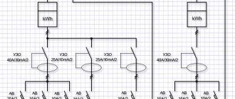
A common circuit for monitoring zero-sequence currents is created by connecting measuring current transformers to a full star circuit, and the windings of the control relay to a combined zero wire.
The current passing through the winding is created by adding all three phase vectors. In symmetrical mode, it is balanced, and during the occurrence of single-phase or two-phase short circuits, the imbalance component is released in the relay.
Features of operation of measuring current transformers and their secondary circuits
When a current transformer operates, a balance of magnetic fluxes formed by currents in the primary and secondary windings is created. As a result, they are balanced in magnitude, directed counter and compensate for the influence of the created EMF in closed circuits.
If the primary winding is opened, then current will stop flowing through it and all secondary circuits will simply be de-energized. But the secondary circuit cannot be opened when current passes through the primary, otherwise, under the influence of the magnetic flux in the secondary winding, an electromotive force is generated, which is not wasted on the flow of current in a closed circuit with low resistance, but is used in idle mode.
This leads to the appearance of a high potential on open contacts, which reaches several kilovolts and is capable of breaking through the insulation of secondary circuits, disrupting the operation of equipment, and causing electrical injuries to operating personnel.
For this reason, all switching in the secondary circuits of current transformers is carried out according to a strictly defined technology and always under the supervision of supervisors without breaking the current circuits. For this use:
special types of terminal blocks that allow you to install an additional short circuit during the break of the section being taken out of operation;
test current blocks with short-circuiting jumpers;
special switch designs.
Emergency process recorders
Measuring instruments are divided according to the type of parameter recording when:
nominal operating mode;
the occurrence of overcurrents in the system.
The sensitive elements of the recorders directly perceive the signal received by them and also display it. If the current value arrived at their input with distortion, then this error will be entered into the readings.
For this reason, instruments intended for measuring emergency currents, rather than rated ones, are connected to the protection cores of current transformers, rather than measurements.
Read about the design and operating principles of voltage measuring transformers here: Voltage measuring transformers in relay protection and automation circuits