The more sections there are in a power plant, the more difficult it is to maintain the same voltage level, therefore, with three or more sections, the busbars are connected into a ring. Arresters are included in the substation design as protective devices. The power supply for the MV substation's own needs is carried out from a special bus, to which electricity is supplied via 0.4 kV inputs from transformers 7 and T2. Single-line diagram of the enterprise's power supply. Part 1.
A significant disadvantage is the use of disconnectors as operational devices. We have extensive experience working with electrical infrastructure, including high-voltage, which allows us to carry out any tasks, regardless of their level of complexity. All elements are connected to each other in a certain sequence, ensuring the operation of the entire circuit. The switchgear circuit between the working jumper and the transformers is the same as that of the branch or end substation discussed above.
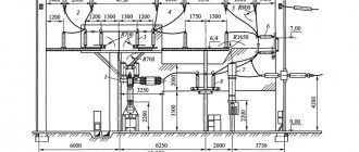
A single-line diagram of a two-transformer substation with a primary voltage of 35 kV is shown in Fig. Power units, MW, have been put into operation; MW units are being put into operation.
Workshop transformer substations, as a rule, do not have a switchgear on the HV side; the supply cable is connected to the transformer through a high-voltage input cabinet, which may contain a high-voltage switching device, a load switch or disconnector, a protection device, a fuse, and a block of busbars that form the power supply circuit above 1 kV. Railway consumers mainly belong to the first and second categories, and for their power supply they often use transformer substations with two transformers, one of which can be a backup one. In the substation diagram shown in Fig. All elements are connected to each other in a certain sequence, ensuring the operation of the entire circuit.
Transformer operating principle
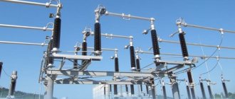
Electrical substations - connections
An electrical diagram, or rather the choice of an electrical diagram for substation connections, is important for the design of electrical circuits. Let's consider options for connecting the substation to the power supply network (ES).
Symbols in the figure
CPU: The power supply center of the network is the voltage buses of a power plant (ES) or substations (SS) of the highest voltage level.
PS 1: This PS is called a dead-end PS. It receives power from one side of the electrical grid. Power is supplied via 1 power line or 2 parallel power lines. A dead-end PS feeds only its consumers and is not transmitted further.
PS 2: This PS is called a branch PS. It is connected without switching devices, by a tap to the 1st or 2nd pass-through power line. This substation connection is not expensive, but is inconvenient to maintain (to repair the branch substation, you will have to disconnect the line from the power center).
PS 3, PS 4: These are pass-through or transit PSs. These substations are connected to the power grid through switching devices. The connection is made by cutting 2 lines of single-sided power supply or 1 line of double-sided power supply. Transit substations are easy to operate and maintain, but are expensive to install.
PS 5: This is the nodal PS. It is connected to the power center(s) with at least three lines. This type of substations is the most complex and requires complex design.
Similar materials
Diagram of a two-transformer substation with a primary voltage of 35 kV Fig.
The F V3 arrester, which protects the insulation of kV switchgear equipment from overvoltages, is located on the same withdrawable trolley as the TV voltage transformer. Typically, for the 1st and 2nd, two-transformer substations are used, and for the 3rd, installations with one. A bypass bus system can be used when the consumer's operating characteristics require constant operational switching.
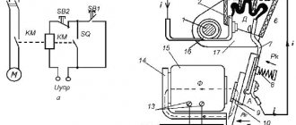
For this purpose, various protective devices are included in its design. The dotted line shows the interlocking connection between disconnectors and their grounding blades, which does not allow turning on the disconnector when the grounding blade is turned on and turning on the grounding blade when the disconnector is on.
The peculiarity of primary circuits is that they are divided into groups: TP and RP, depending on their purpose, design, connection and other characteristics. With this solution, the step-down transformers work in parallel and if one circuit is broken, the switch automatically turns off. The dotted line shows the interlocking connection between disconnectors and their grounding blades, which does not allow turning on the disconnector when the grounding blade is turned on and turning on the grounding blade when the disconnector is on. Four lines depart from the 10 kV buses, supplying consumers. Schematic diagram of a complete transformer substation. Figure 5.
Make a request
But in order for the equipment to be used effectively, its installation must be carried out by specialists from the manufacturer. Diagram of a transformer installation Diagram of small and high power Decisions on this issue are usually made taking into account the power supply system of the facility and the prospects for its development. When replacing any line switch with a bypass switch, you must turn off the QO, turn off the jumper disconnector QS3, and then use the QO for its intended purpose. In this scheme, you can use a bus coupling switch to replace the switch of any connection.
This is followed by a fuse and the main transformer. Schematic diagrams, depending on the method of representation, are divided into single-line and multi-line, expanded and combined.
In the diagram Fig. KV switchgear circuit diagram of a walk-through substation. Symbols of KTP. The switchgear circuit between the working jumper and the transformers is the same as that of the branch or end substation discussed above. Construction of a substation in Germany from A to Z
Connection diagrams for electrical substations
Let's look at the developed electrical connection diagrams for substation 35 to 220 kV. RUNN are conventionally designated low voltage switchgears.
- 1- 2- 3- Power line/transformer with switching device.
- 4-5- simplified diagram for dead-end, branch, and through substations. These circuits use switch bridges and repair jumpers.
- 6- Quadrangle, for networks with 4 connections of 2 power lines and two substations. Allows you to connect any line to any transformer.
- 7- One working section made of busbars. Used for 35 kV with 5 or more connections. For example, two transformers and three lines.
©Elesant.ru
Other articles in the section: Electrical networks
- Automatic circuit breakers
- Types of power transmission line supports by material
- Types of supports by purpose
- Overhead power lines with SIP wires
- Wooden supports for overhead power lines
- Reinforced concrete power transmission line supports
- Reinforced concrete power transmission line supports
- Protection of humans from electric shock, direct and indirect contact
- How does a 380 Volt low voltage consumer receive electricity?
- Cable network wells installation stages
Types of substations and their features
In addition, one should rely on regulatory documentation. Disadvantages of outdoor switchgear: they occupy large areas and are subject to environmental influences such as freezing, dust, and pollution. A second manually operated jumper disconnector QS4 is used when repairing QS3 to create a visible circuit break. Transformer T2 remains in operation, receiving electricity from input W2.
Power supply to critical consumers is provided by at least two lines from different dual reactors, which ensures reliable power supply.
When developing such substation diagrams, it is necessary to select switching devices taking into account the purpose of the installation and its power.
But in order for the equipment to be used effectively, its installation must be carried out by specialists from the manufacturer. Accounting for the energy spent on the substation's own needs is carried out from the secondary voltage side of the TSN. If there is a fault in the transformer, the relay protection trips switch Q2 and sends a pulse to open switch Q1 at the power system substation.
Devices with long-term parallel operation are rarely used. The latter condition is difficult to satisfy in a very complex electrical installation, but a significant simplification of the circuit may make it difficult to satisfy the first condition regarding the reliability of the power supply.
In systems with a grounded neutral, symmetrical three-phase and asymmetrical short circuits can occur: a two-phase; in two-phase through the ground for short circuits at one point; g two-phase through the ground for short circuits at various points. The most difficult issue in protecting a 10/0.4 kV transformer
Power supply system for distribution substations
At the level of substation FGC and IDGC, there are traditionally three power supply systems:
- Substation auxiliary power supply system (MV);
- Operating direct current system (OPS);
- Guaranteed Nutrition System (GPS);
At the level of district distribution networks, SOPT and SGP are absent.
Auxiliary power supply system
MV are intended to supply consumers of the substation of the first category (allowing an interruption in power supply during the operation of the automatic transfer switch) and the second category. In the SN of substation FSK and IDGC, an auxiliary switchboard (SCHSN) is used, which has two or more independent inputs. Each of the ShchSN inputs is connected to the output of its own step-down transformer, the transformer input, in turn, is connected to the medium voltage cell. To quickly switch inputs in the event of a voltage failure on one of them, an ATS is used.
The average power of the MV system for FSK substation is 320 kVA, the cost of the power supply unit is 6 - 8 million rubles, for the IDGC substation the power supply voltage is 100 kVA, the cost of the power supply unit is 2 - 3 million rubles.
Also, as a third independent power input for substation FSK's own needs, diesel generator sets are sometimes used, designed for both the full MV load and part of it.
System of operational direct current and guaranteed power supply
SOPT and SGP have similar functions; they provide electricity supply to consumers of the first and special categories. Some of these consumers can be powered by both alternating (SGP) and direct (SOPT) voltage.
The composition of SOPT is divided for substation FGC and IDGC and includes one or two batteries, chargers and one or two DC switchboards. The COPT also includes operating current distribution cabinets - direct or alternating, as well as operational current cabinets.
Table 2 - Approximate composition of SOPT for substation FGC and IDGC
| Name | PS FSK | PS IDGC |
| AB | 2 | 1 |
| SHPT | 2 | 1 |
| memory | 3 — 4 | 2 |
| MEAL | According to the PD | — |
| SHOT | 1 — 2 | — |
| Cost, million rubles. | 10 — 12 | 4 — 6 |
According to [1], the SOPT must provide operating and backup power to the following main electrical receivers:
- relay protection devices;
- control devices and drives of high-voltage circuit breakers;
- alarm devices;
- emergency automatic devices;
- commercial electricity metering devices;
- communication devices providing transmission of relay protection and automation signals;
- drives of automatic input and sectional switchboards
- own needs (ShCHSN) with a voltage of 0.4 kV.
SOPT must provide backup power:
- automated process control system backup power inverters;
- emergency lighting lamps for battery rooms,
- OPU,
- relay board,
- ZRU, pumping rooms, fire extinguishing valve chambers.
The SGP, as a rule, includes electrical voltage converters using the double on-line conversion method, to the DC link of which a battery is connected, power from which is provided when the voltage at the system input disappears. In this case, the transition time to battery power is zero. In addition, the SGP includes a bypass - a backup line through which the load is supplied in the event of a converter malfunction or in the event of a short circuit at the output. Both UPSs (uninterruptible power supplies with their own built-in battery) and uninterruptible power supply units (UPS), which, as a rule, are designed for high power, can be used as UPS. In this case, a substation battery can theoretically be used as a battery, the energy intensity of which should be increased accordingly, but in equipment supply projects such solutions were not included only for generation facilities.
Implementation of an operational direct current system using the example of the Vostochnaya 330 kV substation (MES North-West)
Composition of SOPT
SOPT for the Vostochnaya substation 330 kV includes two batteries with a capacity of 600 Ah each, four switchboards with a nominal value of 160 A each, two switchboards with switching devices at the input from the battery with a nominal value of 250 A and operational current distribution cabinets. The list of equipment is presented in the table.
| Position | Type | Denomination | Qty | Note |
| AB | VB2312 | 600Ah | 2 | |
| ZVU | NRT 160.220 | 160A | 4 | |
| Remote fuse cabinet | SHWAB 250.220 | 250A | 2 | |
| SHPT | SHPT 250.220 | 250A | 2 | Two panels per panel |
| MEAL | SHOL X.220 | 25/40A | 8 | Of these, 2 are for powering the operational blocking circuits |
| Emergency lighting cabinet | 20A | 1 |
A single-line diagram of the SOPT is presented in Appendix B.
The SOPT provides power to relay protection and automation terminals, automated process control systems and control circuits for switching devices, automation and signaling in normal modes and for two hours in the event of a complete blackout of the MV substation. SOPT is divided into two mutually redundant parts. DC consumers are distributed among themselves in such a way that the failure of one of them does not lead to the loss of the main functions of relay protection and automation, PA, automated process control systems and control of switching devices. In normal mode, power supply to COPT consumers is carried out from the PVU, the battery takes over the load in the event of peak modes (simultaneous switching of several groups of consumers, the occurrence of a short circuit), as well as in emergency mode. Since the substation uses modern SF6 high-voltage circuit breakers, which do not consume large inrush currents during switching, there is no division into SHB and SHU busbars in the switchboard; each switchboard consists of two equivalent cabinets, each cabinet uses one bus section.
A three-level protection system is used. At the first (in the cabinet of remote fuses) and middle (on the outgoing feeders of the switchboard sections) fuses are used, at the third level (in the SHROT) modular automatic protective switches are used.
According to the requirements [1], three-level protection provides:
- Redundancy of lower-level protective switching devices by higher-level protection and protection devices in the entire range of short-circuit currents;
- Selectivity of ZKA in the entire range of short-circuit currents;
In addition, the SOPT is divided into two zones - “clean”, which is used to power the MT RPA circuits and circuits that do not extend beyond the relay protection room, and “dirty” - which is used to power the control circuits of switches in the switchgear and outdoor switchgear. Galvanic connection of the two zones occurs only on the power supply buses, which reduces the likelihood of a decrease in the voltage of the power supply circuits of the MT RPA in the event of a short circuit in the cables supplying remote consumers. In addition, to power the operational blocking circuits, the use of galvanically decoupling DC/DC converters 220V/220V is provided, which are used to galvanically isolate the main SOPT and the SOPT OB power supply circuits from each other. Measures are also provided to ensure EMC, in particular, the cables supplying MT RPAs have protective screens.
SOPT loads
The load of the COPT is divided into constant and intermittent, the operating mode of the COPT is normal (in which the MV power supply is present) and emergency (in which the MV power supply is absent).
| Consumer | Normal mode | Emergency mode | ||
| Constant load | Jog load | Constant load | Jog load | |
| RPA and PA | 28 | — | 28 | — |
| Emergency lighting | — | — | 18 | — |
| APCS | — | — | 55 | — |
| Communication system | — | — | 23 | — |
| I/O switches | — | 282* | — | 282* |
| total | 28 | 282 | 124 | 282 |
*- mode is being considered. at which 9 I/O switches are triggered simultaneously
Thus, the shock load does not depend on the operating mode of the COPT and mainly affects the choice of battery capacity. The constant load depends significantly on the operating mode; in normal mode, only MT RPAs are powered by direct current.
Electricity consumers at substation
Table 3 - Consumers of the first and special categories at substations
| Consumer | D.C | AC GPU | Alternating current |
| Microprocessor protection terminals | Yes | can | No |
| Control circuits for high voltage circuit breakers | Yes | No | No |
| Power supply for substation servers | No | can | Yes |
| Upper level automated process control system (AWS) | Yes | Yes | No |
| I/O switch drives | Yes | No | can |
| Emergency lighting | Yes | No | Yes* |
| Fire alarm | No | No | Yes |
| Fire extinguishing automation (valves, fire pumps) | Yes | No | No |
| Gate valve motors (dry pipes) | No | No | Yes** |
| Communication means PS | Yes*** | No | No |
| Substation alarm circuits (at the central control panel) | Yes | No | Yes |
| Cabinets for blocking disconnectors (power supply circuits for discrete inputs of automated process control systems) | Yes | No | |
| Drives for visible disconnectors | No | No | Yes |
| Ventilation and air conditioning | No | No | Yes |
| Transformer cooling | No | No | Yes |
| Heating | No | No | Yes |
| Lighting (non-emergency) | No | No | Yes |
· * - in non-emergency mode
** - used in conjunction with AVR
*** - 48 VDC
Power switching devices
During operation, transformer substations must be connected to voltage or taken out of operation for preventive maintenance or in the event of emergencies and malfunctions. For this purpose, switching devices are used, which are created in various designs and can:
1. turn off emergency currents of the maximum possible values;
2. switch only workloads;
3. ensure a break in the visible section of the electrical circuit by switching only when the voltage is removed from the equipment.
Switching devices capable of switching off emergency situations operate in automatic mode and are called “circuit breakers”. They are created with various load switching capabilities due to design features.
Based on the principle of using the stored energy inherent in the operation of the actuator, they are divided into:
- spring;
- cargo;
- pressure;
- electromagnetic.
According to the methods of extinguishing the electric arc that occurs during shutdowns, they are classified into:
- air;
- SF6;
- vacuum;
- oil;
- autogas;
- electromagnetic;
- autopneumatic.
To control exclusively operating modes, characterized only by nominal network parameters, “load switches” are created. The power of their contact system and the speed of operation allow successful switching in the normal state of the circuit. But they cannot be operated to eliminate short circuits.
When an electrical circuit breaks under load, an electric arc is created, which is eliminated by the design of the switch. In a de-energized circuit, simpler devices are used to isolate a certain section from the voltage:
1. disconnectors;
2. separators.
Disconnectors are usually operated manually when the voltage is removed. At substations of 330 kV and above, the disconnectors are controlled by electric motors. This is due to the large dimensions and mechanical forces that are difficult to overcome manually.
When the disconnector is turned on, a section of its circuit is assembled into an electrical circuit, and when turned off, it is removed.
Separators are created to automatically separate the voltage from the protected area when a dead break is created on it by a remote switch.
Existing standards:
- Organization standard of JSC FGC UES STO 56947007-29.120.40.041-2010 Operational direct current systems for substations. Technical requirements
- Typical list of signals coming from relay protection and automation systems, automated control systems, automated information monitoring systems and substation engineering systems in automated process control systems, Moscow 2010.
- Guidelines for the design of operational direct current systems (OCPT) of the UNEG substation Typical design solutions, 2011
- Standards for technological design of alternating current substations with higher voltage 35-750 kV (NTP PS) Organization standard
- Schematic diagrams of electrical switchgear of substations with voltage 35-750 kV. Standard solutions, Energosetproekt, 2006.
- General technical requirements for microprocessor protection and automation devices for power systems RD 34.35.310-97
- Guidelines for engineering calculations in operational direct current systems to prevent incorrect operation of discrete inputs of microprocessor-based relay protection and automation devices in case of ground faults in operational direct current circuits of UNEG substations
NO COMMENTS YET
Power plants operating in parallel in the power system differ significantly in their purpose. Complete transformer substations are produced at a number of factories.
The hexagon diagram in Fig. 1 has become quite widely used. The admissibility of the latter operation depends on the power of the transformer and its rated voltage. Complete transformer substations hereinafter referred to as KTP or their parts, installed indoors, are classified as indoor installations; those installed in the open air are classified as outdoor ones.
Normally one jumper switch QS3 is off, all switches are on.
Switch Q1 in the bridge is turned on if power transits through lines W1, W2. Sectional circuits To power several power transformers and distribution switches connected to power electrical receivers, a circuit with one busbar system can be used.
We recommend: Measuring the resistance of grounding devices frequency
Complete transformer substation device connection diagram
The branch substation is connected by a blind tap to one or two passing lines. The latter condition is difficult to satisfy in a very complex electrical installation, but a significant simplification of the circuit may make it difficult to satisfy the first condition regarding the reliability of the power supply. Structural diagrams of thermal power plants Figure 2. Features and service life Requirements for installing lightning protection The choice of any power supply system must be made in accordance with the planned loads.
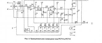
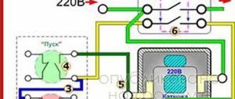
We have extensive experience working with electrical infrastructure, including high-voltage, which allows us to carry out any tasks, regardless of their level of complexity. All identical devices are marked with numbers, that is, if there are 2 current relays, the designations will look like - 1KA and 2KA. But in order for the equipment to be used effectively, its installation must be carried out by specialists from the manufacturer.