In tapes with a supply voltage of 24 volts, the operating current is two times less than in tapes with 12 volts. Thanks to this, the voltage drop on the thin conductive tracks of the tape is reduced and the drop in the brightness of the LEDs along the length is less than on tapes with a voltage of 12 volts.
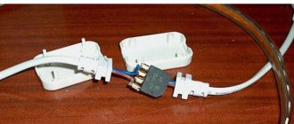
To achieve uniform illumination and maximum luminous efficiency, it is recommended to connect the 5-meter tape on both sides.
If you look closely at a 12-volt tape, you will notice that the cutting ratio of such a tape is equal to three LEDs. That is, we can safely cut a piece of tape containing 3 LEDs, power it from 12V, and it will work autonomously. For a 24-volt tape (Fig. 2), the cutting ratio already includes 6 LEDs, i.e. twice as much (24 Volts divided by 12 Volts = 2, it’s simple).
What does voltage affect in this case, and why is a 24 Volt tape better? After all, at 12 Volts, the cutting ratio is smaller, and it can be powered from a regular 12-volt battery (which is often used by motorists). The answer lies on the surface. According to the laws of physics, the higher the voltage, the lower the current strength (I=P/U, where I is current strength (A), P is power (W), U is voltage (V). Therefore, a current of 220 Volts comes to our apartments , and inside electrical appliances there are voltage-reducing devices.220 Volts in the network gives less load on the wiring.
In other words, the higher the voltage of your LED strip, the lower the current flowing through this very strip will be, therefore, at 24 Volts: a) the strip will heat up less, b) from one end you can power a longer segment (not 5 meters, as with 12 Volts, but already 10 meters), c) in many cases, the power supply circuit for long sections is simplified SEVERAL TIMES.
Now we know that it is more profitable to take a 24 Volt tape, especially since it costs the same as a 12 Volt tape.
In tapes with a supply voltage of 24 volts, the operating current is two times less than in tapes with 12 volts. Thanks to this, the voltage drop on the thin conductive tracks of the tape is reduced and the drop in the brightness of the LEDs along the length is less than on tapes with a voltage of 12 volts.
To achieve uniform illumination and maximum luminous efficiency, it is recommended to connect the 5-meter tape on both sides.
If you look closely at a 12-volt tape, you will notice that the cutting ratio of such a tape is equal to three LEDs. That is, we can safely cut a piece of tape containing 3 LEDs, power it from 12V, and it will work autonomously. For a 24-volt tape (Fig. 2), the cutting ratio already includes 6 LEDs, i.e. twice as much (24 Volts divided by 12 Volts = 2, it’s simple).
What does voltage affect in this case, and why is a 24 Volt tape better? After all, at 12 Volts, the cutting ratio is smaller, and it can be powered from a regular 12-volt battery (which is often used by motorists). The answer lies on the surface. According to the laws of physics, the higher the voltage, the lower the current strength (I=P/U, where I is current strength (A), P is power (W), U is voltage (V). Therefore, a current of 220 Volts comes to our apartments , and inside electrical appliances there are voltage-reducing devices.220 Volts in the network gives less load on the wiring.
In other words, the higher the voltage of your LED strip, the lower the current flowing through this very strip will be, therefore, at 24 Volts: a) the strip will heat up less, b) from one end you can power a longer segment (not 5 meters, as with 12 Volts, but already 10 meters), c) in many cases, the power supply circuit for long sections is simplified SEVERAL TIMES.
Now we know that it is more profitable to take a 24 Volt tape, especially since it costs the same as a 12 Volt tape.
Protection
As I said at the beginning of the article, the power supply must protect PC components from damage in emergency situations. Therefore, when choosing a block, you need to look at the presence of protection circuits.
- Over-Voltage/Undervoltage Protection (OVP/UVP): OVP protects the hardware from problems with the block itself, and UVP protects the block from high external voltage.
- Single Line Overload Protection (OCP): Prevents all power from being sent to any one power line. This is done to ensure that any component cannot fail due to excess power.
- Overload Protection (OPP): Roughly speaking, OCP on the 12V line is the OPP for the entire power supply.
- Overheat protection (OTP).
- Short Circuit Protection (SCP).
The device of a simple transformer
The main element of the transformer is the relay. The coils themselves are installed with different windings. Magnetic cores are available with cores. In terms of current conductivity, they differ quite significantly. It is also important to mention that some modifications include special extenders. In this case, much depends on the operating frequency parameter.
Insulators in transformers are designed to protect the core from overloads. To rectify direct current, transceivers are installed in devices. They are produced in orthogonal and tuning types.
The principle of operation of the SMPS and its design
A switching power supply is a device that operates on the principle of an inverter, that is, it first converts alternating voltage into direct voltage, and then again converts it into an alternating voltage of the desired frequency.
Ultimately, the last stage of the converter is still based on voltage rectification, since most devices still operate at a reduced DC voltage. The essence of reducing the size of these power supply and converting devices is based on the operation of the transformer. The fact is that the transformer cannot operate with constant voltage. Simply, an EMF (electromotive force) will not be induced at the output of the secondary winding when direct current is supplied to the primary. In order for voltage to appear on the secondary winding, it must change in direction or magnitude. Alternating voltage has this property; the current in it changes its direction and magnitude with a frequency of 50 Hz. However, in order to reduce the size of the power supply itself and, accordingly, the transformer, which is the basis of galvanic isolation, it is necessary to increase the frequency of the input voltage. At the same time, pulse transformers, unlike conventional linear ones, have a ferrite core of the magnetic circuit, and not a steel core made of plates. And also modern power supplies working on this principle consist of:
- mains voltage rectifier;
- a pulse generator operating on the basis of PWM (pulse width modulation) or a Schmitt trigger;
- DC stabilized voltage converter.
After the mains voltage rectifier, a pulse generator using PWM generates it into alternating voltage with a frequency of about 20–80 kHz. It is this increase from 50 Hz to tens of kHz that makes it possible to significantly reduce both the dimensions and weight of the power source. The upper range could be larger, however, then the device will create high-frequency interference, which will affect the operation of radio frequency equipment. When choosing PWM stabilization, it is imperative to also take into account the higher harmonics of the currents.
Even when operating at these frequencies, these pulsed devices produce high-frequency noise. And the more of them in one room or in one enclosed space, the more of them there are in radio frequencies. To absorb these negative influences and interference, special noise suppression filters are installed at the input of the device and at its output.
This is a clear example of a modern switching power supply used in personal computers.
If a radio amateur invents a circuit himself, he must look into the reference book on radio components. The reference book is the main source of information in this case.
General characteristics of inverters 24-220
The inverter models produced have a variety of parameters and technical characteristics. This makes it possible to choose the most optimal option for specific operating conditions. However, the general functionality of the devices is almost the same, so as an example we can take a 24V - 220V voltage converter with a power of 200 watts.
This device is designed to receive alternating voltage from the current of a 24V battery. The output produces a stable voltage of 220V, with a frequency of 50 Hz, suitable for operating standard household appliances. All inverters of this type are equipped with their own built-in protection against short circuits, overheating and overloads.
The 24V-220V inverter in question is best suited for use with a car battery. It allows you to most effectively solve priority everyday problems during travel and outings. In addition to the standard socket, the case has a USB connector to which mobile devices can be connected.
The converter operates not only from the battery, but also from the cigarette lighter. It also interacts well with a mobile power station using solar panels.
The main technical characteristics are the following: input voltage - 20-30 volts, output - 220-240 V. Constant output power - 200 W, peak power - 400 W. The green LED indicates normal operating mode, the red light turns on when the protection is triggered. The efficiency is 90%.
The main function of the inverter is to convert the DC current from the battery into alternating current suitable for connecting household electrical appliances. The output voltage is 220 volts, with a frequency of 50 Hz. For ease of use, each inverter device is equipped with a standard socket. Passenger cars typically use 12 to 220 V inverters. The more powerful 24 to 220 V inverter is used in trucks and buses, and as the main component of an off-grid electrical system.
What can 12 or 24 volt voltage be used for in everyday life?
In domestic environments, low voltage power supplies are often used. Portable/stationary electrical and electronic devices, as well as some lighting devices, are powered from 12 or 24V DC voltage:
- cordless electric drills, screwdrivers and electric saws;
- stationary pumps for watering gardens;
- audio-video equipment and radio-electronic equipment;
- video surveillance and alarm systems;
- battery-powered radios and players;
- laptops (netbooks) and tablets;
- halogen and LED lamps, LED strips;
- portable ultraviolet irradiators and portable medical equipment;
- soldering stations and electric soldering irons;
- chargers for mobile phones and power banks;
- low-current power supply networks in places with high humidity and landscape lighting systems;
- children's toys, Christmas tree garlands, aquarium pumps;
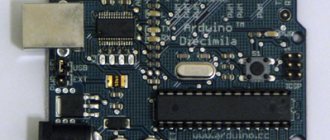
- various homemade radio-electronic devices, including those based on the popular Arduino platform.
Most devices run on batteries and Li-ion batteries, but the use of commodity items is not always justified in terms of operating costs. Batteries can be charged 300–1500 times, but galvanic cells with high energy capacity and low self-discharge current are expensive. It will be noticeably cheaper to purchase batteries, especially salt and alkaline ones, but such elements will have to be changed frequently. Moreover, to provide a supply voltage of 12 V, you will need 8 series-connected AA or AAA batteries or 1.5-volt “tablets” in a 27A housing.
Therefore, in places with access to a 220 V 50 Hz household network, it is more rational to use a power supply to power electrical receivers with an amperage of more than 0.1 A.
Transformers with dielectrics
Models with dielectrics are used for compressors. In production, devices of this type are quite in demand. They are capable of operating from a single-phase circuit.
It is also important to consider that the frequency of the models is on average 35 Hz. Thus, large current overloads rarely occur. Insulators are not used in the presented models. The dielectrics are installed directly near the magnetic core.
Let's consider the operation of a 24-volt stabilizer using the example of a power source for an air humidifier for an incubator. His nutrition is precisely this value. The boost stabilizer circuit is shown in the figure. Its main element is the UC 3843 microcontroller. This circuit was given in the documents for this chip model.
Flyback switching power supply
This is one of the types of switching power supplies that have galvanic isolation of both primary and secondary circuits. This type of converter was immediately invented, which was patented back in 1851, and its improved version was used in ignition systems and in horizontal scanning of televisions and monitors, to supply high-voltage energy to the secondary anode of the kinescope.
The main part of this power supply is also a transformer or maybe a choke. There are two stages in its work:
- Accumulation of electrical energy from the network or from another source;
- Output of accumulated energy to the secondary circuits of the half-bridge.
When the primary circuit opens and closes, current appears in the secondary circuit. The role of the disconnecting key was most often performed by a transistor. To find out the parameters of which you must use the reference book. This transistor is most often controlled by a field-effect transistor using a PWM controller.
PWM controller control
The conversion of the mains voltage, which has already passed the rectification stage, into rectangular pulses is performed with some periodicity. The turn-off and turn-on period of this transistor is performed using microcircuits. The PWM controllers of these keys are the main active control element of the circuit. In this case, both forward and flyback power supplies have a transformer, after which re-rectification occurs.
In order to ensure that the output voltage in the SMPS does not drop with increasing load, a feedback loop was developed that was inserted directly into the PWM controllers
This connection makes it possible to completely stabilize the controlled output voltage by changing the duty cycle of the pulses. Controllers operating on PWM modulation provide a wide range of output voltage changes
Microcircuits for switching power supplies can be of domestic or foreign production. For example, NCP 1252 are PWM controllers that have current control and are designed to create both types of pulse converters. Master pulse generators of this brand have proven themselves to be reliable devices. NCP 1252 controllers have all the quality features to create cost-effective and reliable power supplies. Switching power supplies based on this microcircuit are used in many brands of computers, televisions, amplifiers, stereo systems, etc. By looking in the reference book, you can find all the necessary and detailed information about all its operating parameters.
12V LED strip - advantages
The most important advantage of twelve-volt tapes is the availability of this voltage. The vast majority of batteries produce exactly 12 volts.
This voltage can be found in cars, motorcycles, and computer system units.
Specialized step-down power supplies also go primarily to 12 volts.
To find another voltage, you will need to try harder. It is precisely based on this availability that the scope and range of 12 volt LED strips is much wider than all others.
These types are used for illumination in cars, built into portable lightboxes, advertising signs, temporarily illuminated road signs, etc.
Where the tape can only be connected from a battery, due to the lack of 220V alternating voltage, 12-volt light sources are always chosen.
The second advantage is the cutting frequency. If you have ever come across the rules for working with LED strip, then you probably know that you cannot just cut it off anywhere.
For this purpose, special markers are indicated on the substrate.
So, for 12V strips, this multiplicity on average is only 3 LEDs.
The length of this section depends on the backlight power and ranges from 2.5 cm to 5 cm.
In rare cases, you can find models with a multiple of up to 1cm!
Imagine how much more convenient it is to install. You won’t have to rack your brains about where to hide the extra tails that don’t fit into the length of your light lines on the ceiling.
The third plus is safety. No one will deny that 12V is safer than 24V. Such low voltage will not do anything to you, even if you accidentally touch the wires or contacts on the tape with wet hands.
So in places where your children can reach the tape, use only 12 volts. Although this does not in any way eliminate the need to insulate all exposed live parts of the backlight.
Application areas of LED strips
Using tape to illuminate a mirror
The main function of LED devices is to organize artificial lighting in a specific room or outside a building. In this case, the LED strip replaces conventional light bulbs, being located along the perimeter of the ceiling or in a pre-marked area. This approach to decorating free spaces allows you to improve the quality of the light picture and evenly illuminate the objects being served. Thanks to this, it is possible to increase the comfort of people’s stay in rest areas or in the work area.
Typically, for these purposes, tapes with elements of increased brightness, characterized by a warm white glow, are used. The use of low-power lighting devices, even if they are evenly distributed around the entire perimeter, will require the installation of an additional lamp.
Use for decorative purposes
LED strip under a suspended ceiling
Modern LED lighting devices are very popular in decorating practice and are widely used in the following areas:
- lighting of shelves, construction niches and stairs;
- architectural zoning of work spaces;
- highlighting elements of landscape areas with flower beds and trees;
- decoration of building facades, as well as individual architectural details.
In addition, their help is resorted to when it is necessary to focus attention on elements of the environment: furniture, mirrors, paintings and other objects. To meet constant demand, manufacturers have developed many varieties of LED strips, which provide various visual effects.
Led strip 24 volt
The main advantage here is the current, that is, what was a disadvantage of the previously considered model.
For a 24-volt one with the same power, the current consumption will be half as much. What does this mean in practice?
Firstly, you can connect all the lighting with wires that are twice as thin.
Instead of a copper cable with a cross-section of 1.5mm2, only 0.75mm2 is enough. Due to the lower current, losses will be halved. This means that the backlight can be made much longer.
Thus, the standard length for connecting a 12V LED strip is 5 meters.
After which, to the next section of 5 meters, you must extend a separate power supply and connect it in parallel.
The tape cannot be consistently extended beyond this distance.
For 24V tapes, this length is twice as long - 10 meters.
In fact, with two “pieces” you can illuminate the entire ceiling in a room around its circumference.
Electronic transformer
The principle of operation of an electronic transformer is similar to the classical one - when an alternating voltage is applied to the primary winding, an alternating voltage is also removed from its secondary, but of a different value. The difference is that the reduced voltage has a completely different frequency and curve shape, since it is artificially created by a pulse generator.
An example of an electronic transformer circuit and operating principle is shown in the figure below:
Rice. 2. Electronic transformer
As you can see, in it the supply voltage from the 220 V network is not supplied to the transformer windings, but uses a diode bridge as the main converter from a variable electrical quantity to a constant one. The signal is then fed to output transistors, which act as an electronic switch, which generate pulses of a certain number and frequency. It should be noted that the frequency from the pulse generator can reach several tens of kHz, but then it is supplied to a pulse converter, which is represented by a power transformer.
Pulse transformers, or, as they are also called, pulse power supplies, are widely used in powering fluorescent lamps. However, its location in relation to the powered lighting devices should be in close proximity to reduce losses, load in network wires and heating. Compared to a transformer power supply, a pulsed one has a number of significant advantages:
- Smaller dimensions for the same power, which reduces the cost of the device;
- Has the best parameters in adjusting the supplied voltage;
- Features higher efficiency.
But along with the advantages, the pulse unit also has some disadvantages. The electronic transformer has a much more complex circuit, which entails a decrease in reliability. If you go cheap with the transformer model, the output current will release a lot of impulse noise into the network, which can affect the operation of related equipment.
Reliability
Based on practical use cases, it can be stated that a 24-volt LED strip is more reliable than a 12-volt one.
This is not explained by any improved parameters. They have nothing to do with it.
The thing is that these types are most often supplied by normal, well-established manufacturers.
More budget suppliers either do not have them in stock, or this line is limited to only one or two copies.
The curious user will wonder, what about 36 or 48 volts? After all, here the currents will be even smaller, which means the benefits and advantages should increase many times over.
Everything seems to be correct, however:
- firstly, such tension under unfavorable circumstances can already be dangerous for a person
- secondly, very large cutting ratios are inconvenient (up to 20cm!)
Therefore, such models are not widely used in everyday life.
Schematic diagrams
To select a scheme, you need to select the basic elements on which it will be based:
- high frequency converter;
- voltage rectification element.
High-frequency transformer - a circuit element where a transformer is used (Fig. 2)
Rice. 2 High frequency transformer circuit
This scheme is one of the simplest, but it has some disadvantages:
- it is necessary to increase the amplitude of the pulses to obtain high current power;
- the use of a large transformer, since it is based on a partial magnetic hysteresis loop.
Of the above-mentioned disadvantages, the circuit is often applicable to low-power devices.
Voltage rectifiers
Such elements are divided into 3 types (Fig. 3):
Rice. 3 Types of voltage rectifier circuits
- Half-wave. One of the simplest circuits using a small number of semiconductors. Its imperfections include a high voltage pulse at the output.
- With zero point. Has a device with a high rectification coefficient. The disadvantage of this scheme is the network transformer, which creates large overall dimensions.
- Bridge circuit. Similar to point 2, except for the absence of a transformer converter. Instead, a capacitive filter is used. But this element has a very large current pulse at the output.
Having examined the types of operating circuits of sources, it is worth noting that the devices of each circuit are guaranteed to work correctly if all elements of the circuit are correctly selected and connected.
Safety precautions
When operating the pulse unit, you must adhere to simple safety rules. They will help to avoid injuries of varying severity and reduce the likelihood of an emergency.
Basic precautions:
Repair or maintenance work should only be carried out when the unit is disconnected from the power supply. This will help avoid electric shock and all the problems associated with it. Power capacitors can remain energized for a long time even after the unit is turned off. Because of this, it is prohibited to perform any operations on the device immediately after turning it off.
It is prohibited to store flammable objects and combustible materials near the operating unit. A small spark can cause a fire, which can lead to many problems. It is not recommended to repair the structure if there are grounded devices next to it. Do not store or use the device in a damp place, as this may result in a short circuit. A master working with a pulsed energy source must stand on a special mat made of dielectric material
This simple measure will significantly reduce the risk of electric shock. Do not repair the device while standing on a floor made of cement or any other conductive material. It is not recommended to leave a working homemade unit unattended.
When you turn on a home-made unit for the first time, you must carefully check all structural elements for safety. It is important to avoid contact with water or any other liquids on electrically powered components of the device. Preventive and repair measures should be carried out using special protective clothing (sleeves, gloves) and tools with insulated handles. The homemade device should be stored out of the reach of children and pets. If any accident or unforeseen situation occurs, you must immediately turn off the power to the equipment. Only after this can you look for the cause of the breakdown and eliminate it.
A pulsed energy source is a useful and necessary device that you can not only buy ready-made, but also make it yourself. The second option is more popular, as it allows you to get a high-quality device with minimal financial and time costs.
Car stabilizer for 24 V
Let's consider one simple electronic homemade product. This will be a 24 volt stabilizer. But this is not an ordinary stabilizer, but a reliable and powerful linear device. We've been using it for a long time. The radar detector in the car is connected to power through this circuit. It is equipped with internal stabilization. However, sometimes it fails, and one day the detector failed.
We did not send it in for repairs, but simply pulled out the burnt stabilizer from it and connected it from a separate stabilizer made by ourselves. It has been working fine for about two years now. But now a similar scheme is needed again. Not just for a car, but for household purposes.
It is necessary to connect a low frequency amplifier to the power supply. Its power supply voltage is 24 volts. The stabilizer is based on the L 7824 microcircuit. This microcircuit can provide a current of 1.5 A. However, at a significant current, it gets very hot and reduces its stability. To solve this problem and increase the current with which stabilization will take place, a simple circuit has been developed.
In this circuit, amplification will occur through the operation of a transistor connected in parallel. The circuit is simple and does not require expensive, scarce parts. It can be mounted using a hinged installation method to check operation.
A cooling radiator is required for such a circuit, since the circuit is linear and significant power is dissipated on the semiconductor. The linearity of the circuit is a positive point for the amplifier, since there is no extraneous interference from the PWM modulator. The circuit board was etched in a solution of citric acid and hydrogen peroxide.
Advantages of electronic converters
The main advantages of devices built on the basis of ET include the following features of the circuit:
- the output transformer of the power supply will not start without connecting a load to it - it will go into active mode only if a lamp with a light bulb is connected to it;
- in addition to the gentle operation of electronic circuit elements, this property of the electric vehicle allows you to save on consumed electricity;
- The product easily implements a system of protection against dangerous overloads and short circuits.
More complex half-bridge circuits are often taken as a sample used for making a home-made power supply on such a transformer. They are usually built on the basis of drivers such as IR2153 or similar electronic components. As an additional option, they are equipped with an indicator LED that signals the presence of high-frequency oscillations.
Classification by circuit solutions
There are only three classes, each of which differs from the others in the way the stabilizer is constructed. In these blocks it must be powerful and low voltage.
Transformerless stabilizer
We can talk about this power supply like this - there are many shortcomings, the advantages are questionable. The advantages include small size and weight. The biggest drawback is the low efficiency. Therefore, these blocks have low popularity. They are usually installed in TVs and computers. Perhaps that's all. The disadvantage is the impossibility of constant work. That is, such power supplies must be turned off during the day. Therefore, they are not installed in various systems (security, fire). Although experts assure that the future lies with these modifications
It is important to equip them correctly
Transformerless stabilizer
PWM stabilizers
If we talk about the advantages, then this is a high efficiency, plus an acceptable price (one of the lowest), if you purchase a stabilizer operating at a current above 3 A. Unfortunately, there are also disadvantages, where the most important is low reliability. It should be noted that PWM stabilizers are increasingly being used in systems where there is a need to convert one voltage to another. Therefore, they are installed on power supplies, where there are two outputs: one for alternating current, the second for direct current.
Linear stabilizers
Experts agree that these are the most reliable stabilizers on the market. There are also disadvantages - these are the large dimensions and weight of the products, plus the high price. Unfortunately, the efficiency is not very high.
But this is what experience shows. The choice of 24V DC power supply depends on the system in which it will be used. When it comes to alarm systems, security and fire extinguishing systems, then characteristics such as safety margin (long-term operation) and reliability of the device come first. Therefore, consumers are increasingly choosing linear models.
- Firstly, they easily withstand atmospheric influences.
- Secondly, they do not interfere with nearby equipment.
- Thirdly, if you choose a power supply up to 2 A, then these are the cheapest products from the entire line offered.
- Fourthly, one should not discount the upward trend of reducing electricity consumption by various types of equipment. So 24-volt linear power supplies will remain classics for a long time.
Downgrade modifications
A step-down transformer from 220 to 24 volts is often found with a power of 100 watts or more. Devices of this type are used, as a rule, for electric drives. Many models have magnetic cores with relays with strip cores. It is also important to note that the windings in 3 kW devices are installed concentrically. However, modifications with three-layer analogues are available on the market. There are two total outputs for step-down devices.
Some modifications are available with terminals. A step-down transformer 220 to 24 volts weighs no more than 5 kg. The models differ quite significantly in terms of current conductivity. In this case, the type of transceiver must be taken into account. Domestic transformers are mainly sold with orthogonal analogues. However, foreign companies prefer trimmed transceivers. The current overload indicator for models is on average 5.5 A. Some devices are available with switches for phase adjustment.
The nuances of making a power supply for a screwdriver
When making a 12 V power supply with your own hands to connect a screwdriver to the electrical network, you must take into account the following nuances associated with its use:
- The output voltage should be 18–19 V, otherwise the power of the device will be significantly reduced.
- The electronic components of the power supply circuit must correspond to the rated current of the operating screwdriver.
- The size of the assembled unit must be such as to fit into the housing of the battery being removed (in the case of a built-in structure).
Otherwise, the manufacturing stages are similar, as in the case of a separately placed version of the power supply unit.
Auxiliary nodes
The design can include auxiliary components, for example, indicators or voltage switches. The main thing is not to overdo it and make the device in accordance with all standards and recommendations.
Indicator LEDs
The design can include LED indicators, which are used in factory units and chargers. LEDs serve as an indicator that useful operation of the transformer is being performed and the voltage corresponds to the required value.
Ammeter and voltmeter
To make calculations and select elements, as well as to correctly assemble the power supply, you must use an ammeter and a voltmeter.
Multi-band modifications
A multi-range transformer 220 to 24 volts can be used quite easily from a network with a frequency of over 45 Hz. Jumps in the system rarely occur in models. Due to this, electrical equipment works better, and energy consumption is not very high. Comparators in such modifications are of the two-pole type.
The current conductivity of the models exceeds 80 µS. In turn, the overload parameter is usually 5.5 A. Insulators in this case are installed on the taps. Switches are used to avoid various electromagnetic faults. Heat exchangers in structures are used in various capacities. To strengthen them, supports and slats are used. Many models have a liquid cooling system. Magnetic cores are used with high-voltage windings.