The theory of calculating electrical loads, the foundations of which were formed in the 1930s, aimed to determine a set of formulas that provide an unambiguous solution for given electrical receivers and graphs (indicators) of electrical loads. In general, practice has shown the limitations of the “bottom-up” approach, based on initial data on individual electrical receivers and their groups. This theory remains important when calculating the operating modes of a small number of electrical receivers with known data, when adding up a limited number of graphs, and when calculating for 2UR.
In the 1980s–1990s. The theory of calculating electrical loads increasingly adheres to non-formalized methods, in particular, the complex method of calculating electrical loads, elements of which were included in the “Guidelines for calculating electrical loads of power supply systems” (RTM 36.18.32.0289). Probably, working with information databases on electrical and technological indicators, cluster analysis and pattern recognition theory, constructing probabilistic and cenological distributions for expert and professional assessment can finally solve the problem of calculating electrical loads at all levels of the power supply system and at all stages of making a technical or investment decision .
The formalization of calculation of electrical loads has developed over the years in several directions and led to the following methods:
- empirical (method of demand coefficient, two-term empirical expressions, specific electricity consumption and specific load densities, process schedule);
- ordered diagrams, transformed into calculations based on the calculated active power factor;
- actually statistical;
- probabilistic modeling of load diagrams.
Demand Coefficient Method
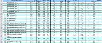
The demand coefficient method is the simplest, most widespread, and is where load calculations began. It consists of using expression (2.20): based on the known (specified) value of Ru and the tabulated values given in the reference literature (for examples, see Table 2.1):
The value of Kc is assumed to be the same for electrical receivers of the same group (operating in the same mode), regardless of the number and power of individual receivers. The physical meaning is a fraction of the sum of the rated powers of electrical receivers, statistically reflecting the maximum practically expected and encountered mode of simultaneous operation and loading of some indefinite combination (implementation) of installed receivers.
The reference data provided for Kc and Kp correspond to the maximum value, and not the mathematical expectation. Summing the maximum values rather than the average inevitably inflates the load. If we consider any group of electrical power supply systems of the modern electrical economy (and not those of the 1930s-1960s), then the conventionality of the concept of “homogeneous group” becomes obvious. Differences in the value of the coefficient - 1:10 (up to 1:100 and higher) - are inevitable and are explained by the cenological properties of the electrical economy.
In table Table 2.2 shows the LGS values characterizing the pumps as a group. When deepening the research on KQ4, for example only for raw water pumps, there may also be a spread of 1:10.
It is more correct to learn to evaluate Cs as a whole for the consumer (section, department, workshop). It is useful to carry out an analysis of calculated and actual values for all similar technology objects of the same level of the power supply system, similar to Table. 1.2 and 1.3. This will allow you to create a personal information bank and ensure the accuracy of calculations. The method of specific electricity consumption is applicable for sections (installations) of 2UR (second, third... Level of the Power System), departments of missile defense systems and workshops of 4UR, where the technological products are homogeneous and change little quantitatively (an increase in output, as a rule, reduces the specific electricity consumption Ay).
Methods for calculating electrical loads
In practical design, there are several such methods for calculating electrical loads using the demand coefficient method:
- calculation of demand coefficient and average power;
- method of specific electricity consumption of specific electrical powers;
- installed capacity method with demand coefficients and - statistical method of calculations;
Example of a power supply project for an industrial enterprise
Back
Forward
If demand coefficients are obtained practically, then the use of this method gives results close to the true values.
Calculation of electrical loads when drawing up a simple power supply diagram using the demand coefficient method is very popular and widespread in calculation engineering and is the simplest method for calculating loads.
Determining the real electrical loads of an energy-consuming facility will give you the opportunity to reasonably and rationally construct technical and economic indicators of power supply systems, determine losses of electricity and power, and select the necessary equipment. Therefore, calculating electrical loads is an important and integral part of organizing the electricity connection of a private or industrial facility.
The results of calculations of electrical loads will influence the technical characteristics of the electrical network and the choice of its elements. Thanks to them, you can ensure the safe operation of electrical networks.
Underestimated results of electrical load calculations lead to overheating of live parts and rapid wear of electrical equipment and materials. And vice versa - an increase in design loads is fraught with additional capital costs for the power supply system and incomplete use of electrical equipment.
When finding the optimal load, various load graph coefficients are used. To find the electrical load using the demand method, you need to know some parameters - the demand coefficients and the total load power of the selected group, as well as the installed power of this group of receivers. In turn, to find the demand coefficient, you need to know the number of electricity consumers operating simultaneously. These calculations can be made using load and concurrency factors.
Based on the obtained calculations of electrical loads for selected groups of consumers, it is possible to calculate the total load of the energy consumption facility. After calculating the total maximum load, the annual electricity consumption of the facility is calculated (for this you need to know the total number of working hours).
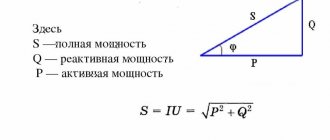
Maximum power method
In real conditions, prolonged operation of a consumer does not mean a constant load at the point of its connection at a higher level of the power supply system. As a statistical value Lud, determined for some previously identified object by power consumption A and volume L/, there is some averaging over a known, usually monthly or annual, interval. Therefore, the application of formula (2.30) gives not the maximum, but the average load. To select SAM transformers, you can take Psr = Pmax. In the general case, especially for 4UR (shop), it is necessary to take into account Kmax as T and take the actual annual (daily) number of operating hours of production with maximum use of active power.
Topic: Calculation of electrical loads of industrial enterprises using the demand coefficient method (page 1)
Practical lesson No. 1
Topic: Calculation of electrical loads of industrial enterprises using the demand coefficient method.
The first stage of designing an industrial enterprise power supply system (EPS) is determining the electrical loads. Based on the magnitude of the calculated electrical loads, the number and power of GPP transformers and shop transformers are selected at various stages of the EPP system, the electrical equipment of the EPP system is checked, etc. Capital costs, operating costs for the EPP system, and the reliability of the electrical equipment depend on the correct assessment of the expected loads.
The initial data for the calculation are the installed capacities in the plant's workshops, which are represented by a load sheet and demand coefficients ().
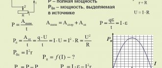
The design load (active and reactive) of the power receivers of the workshops is determined from the relations:
;
,
where is the total installed power of all receivers in the workshop, taken from the initial data; — average demand coefficient, taken according to reference data [2, 3]; - corresponding to the weighted average value of the power factor characteristic of receivers in a given workshop.
The design load of a workshop's lighting receivers is usually determined by the installed power and demand factor for lighting:
,
where is the demand coefficient for lighting, taken from reference data; — installed power of electric lighting receivers.
The value can be found according to the formula:
,
where is the specific load, W/m2; - workshop area.
The total design power of the power and lighting receivers of the workshop is determined from the ratio:
.
Receivers with voltages above 1000 V are counted separately. The calculated active and reactive powers of receiver groups above 1000 V and the total are determined from the expressions:
;
;
,
where , , are the active, reactive and apparent power of the high-voltage load.
Total total power of power and lighting load:
.
Since the workshop transformers and the main step-down substation are not selected at this stage of the calculation, the power losses in them are approximately determined:
,
.
To determine the total design capacity of the enterprise as a whole, it is necessary to take into account all types of load, including:
— power load with voltage up to 1000 V;
— power load with voltage above 1000 V;
— lighting load;
— power losses in transformers;
— power of compensating devices (in order to reduce the number and power of transformers, as well as the consumption of conductor material).
The design power of compensating devices is determined:
,
where is the average annual capacity of the enterprise; — total active power of power and lighting loads; — the number of hours of use of the maximum active power, taken from reference materials; — annual number of operating hours of the enterprise; — reactive power factor of the enterprise load; — specified value of the reactive power factor.
Estimated power of the enterprise, taking into account power losses in transformers, power of compensating devices and different times of maximum loads:
,
where is the coefficient of different times of load maximums (characterizes the displacement of load maximums of individual groups of receivers in time).
Task
Calculate the electrical load of the steel shop of a metalworking plant using the demand coefficient method. The installed active power of the workshop is 3180 kW, the workshop area is 15890 m2.
Solution
We determine the design power load of the workshop:
,
where is the demand coefficient, found from reference materials. We find the rated lighting power and the estimated lighting load of the workshop:
,
where is the specific power of the workshop lighting, determined from reference materials; — coefficient of demand for lighting, found from reference materials.
We find the total design capacity of the workshop:
Homework
Task
Calculate the electrical load of the mechanical repair shop of the sinter plant of a metallurgical plant using the demand coefficient method. The installed active power of the workshop is 7040 kW, the workshop area is 2690 m2.
Practical lesson No. 2
Topic: Choosing the location of power supplies
Example:
Given:
General plan 3
x
2
km with
power loads of workshops (1 class = 0.1 km)
| Parameter | Workshop number | ||||
| C 1 | Ts2 | Central lock | C 4 | Ts5 | |
| R, kW | 100 | 160 | 1000 | 400 | 25 |
| X, km | 0,6 | 1,45 | 2,4 | 1,55 | 0,4 |
| Y, km | 1,45 | 1,25 | 0,9 | 0,55 | 0,4 |
| cos φ | 0,7 | 0,75 | 0,9 | 0,8 | 0,6 |
Required:
• determine the coordinates of the central power station of active loads;
• determine the coordinates of the center of reactive loads;
• apply data to the general plan.
Solution:
| Accepted T g = 800 kW/km2. The radius for the greatest load at the accepted scale is determined |
| Loads can be applied to the general plan at this scale; the scale is approved. The radii of the circles for the remaining loads are determined: |
| The results are entered into the “Summary List of Shop Loads” (Table 1). |
• The electrical load centers (ELC) of each workshop are plotted on the general plan (Fig. 1), the scale of the general plan is mv
=
0.2 km/cm.
• The radii of circles of active and reactive loads are determined based on the scale of the general plan.
• The scale of active (ta)
loads, based on the scale of the general plan. For the smallest load (R5) the radius Ra5 = 0.1 km is accepted, then
| Due to its large volume, this material is placed on several pages: 1 |
Method of specific load densities
The method of specific load densities is close to the previous one. The specific power (load density) y is set and the area of the building or site, department, workshop is determined (for example, for mechanical engineering and metalworking shops y = 0.12...0.25 kW/m2; for oxygen converter shops y = = 0.16... 0.32 kW/m2). A load exceeding 0.4 kW/m2 is possible for some areas, in particular for those where there are single power receivers with a unit power of 1.0...30.0 MW.
Process schedule method
The process schedule method is based on the operating schedule of a unit, line or group of machines. For example, the operating schedule of an arc steel-smelting furnace is specified: the melting time (27...50 min), oxidation time (20...80 min), the number of heats, and technological linkage with the operation of other steel-smelting units are indicated. The graph allows you to determine the total energy consumption per melt, the average per cycle (taking into account the time before the start of the next melt), and the maximum load for calculating the supply network.