Magnetic field sources
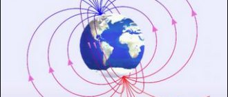
The above experiment clearly demonstrates how anyone can determine the direction of the Earth's magnetic field lines. The arrow of the device will show the directions to the south and north poles. The longitudinal axis of this indicator will coincide with vector (B).
Electromagnetic field of a conductor
If a similar experiment is performed near a current-carrying conductor, the circular location of the power lines can be determined by the movement of the arrow. They form closed rings perpendicular to the center line of the cable.
Electromagnetic induction
A fairly strong field is generated by the induction coil. A practical example is the solenoid of a relay or shut-off device. When turned on, such a unit pulls the metal core inside.
A schematic drawing explains the direction of the retracting force that is generated in the central axis of the solenoid
What is electromagnetic induction
Magnetic induction vector: formula
This phenomenon is accompanied by the appearance of a field in a certain environment, a current in a conductive material, or the polarization of individual objects. Electromagnetic induction depends on the change in magnetic parameters over time or the corresponding movement of functional components.
The exact date of this discovery has been established - 08/29/1831. The author is known - M. Faraday. The scientist revealed the proportional dependence of the EMF in a closed loop on the speed at which the magnetic flux changes.
Basic formulas for calculating the MI vector
The magnetic induction vector, the formula of which is B = Fm/I*∆L, can be found using other mathematical calculations.
Biot-Savart-Laplace Law
Induction EMF formula
Describes the rules for finding B→ magnetic field, which creates a constant electric current. This is an experimentally established pattern. Biot and Savard identified it in practice in 1820, Laplace managed to formulate it. This law is fundamental in magnetostatics. During the practical experiment, a stationary wire with a small cross-section was considered, through which an electric current was passed. For study, a small section of wire was selected, which was characterized by the vector dl. Its module corresponded to the length of the section under consideration, and its direction coincided with the direction of the current.
Interesting. Laplace Pierre Simon proposed to consider even the movement of one electron as a current and, based on this statement, using this law, he proved the possibility of determining the magnetic field of an advancing point charge.
According to this physical rule, each segment dl of a conductor through which electric current I flows forms a magnetic field dB in the space around itself at an interval r and at an angle α:
dB = µ0 *I*dl*sin α /4*π*r2,
Where:
- dB – magnetic induction, T;
- µ0 = 4 π*10-7 – magnetic constant, H/m;
- I – current strength, A;
- dl – conductor section, m;
- r – distance to the point where the magnetic induction is located, m;
- α is the angle formed by r and the vector dl.
Important! According to the Biot-Savart-Laplace law, by summing the magnetic field vectors of individual sectors, it is possible to determine the MF of the desired current. It will be equal to the vector sum.
Biot-Savart-Laplace Law
There are formulas that describe this law for individual cases of MP:
- fields of direct movement of electrons;
- fields of circular motion of charged particles.
The formula for MP of the first type is:
B = µ* µ0*2*I/4*π*r.
For circular motion it looks like this:
B = µ*µ0*I/4*π*r.
In these formulas, µ is the magnetic permeability of the medium (relative).
The law under consideration follows from Maxwell's equations. Maxwell derived two equations for the magnetic field; the case where the electric field is constant is considered by Biot and Savart.
Superposition principle
For MF, there is a principle according to which the total vector of magnetic induction at a certain point is equal to the vector sum of all MI vectors created by different currents at a given point:
B→= B1→+ B2→+ B3→… + Bn→
Superposition principle
Circulation theorem
Initially, in 1826, Andre Ampère formulated this theorem. He analyzed the case with constant electric fields, his theorem is applicable to magnetostatics. The theorem states: the circulation of MF of direct electricity along any circuit is proportional to the sum of the forces of all currents that penetrate this circuit.
Worth knowing! Thirty-five years later, D. Maxwell generalized this statement, drawing parallels with hydrodynamics.
Another name for the theorem is Ampere’s law, which describes the circulation of MP.
Mathematically, the theorem is written as follows.
Mathematical formula of the circulation theorem
Where:
- B→– magnetic induction vector;
- j→ – electron motion density.
This is the integral form of writing the theorem. Here, on the left side one integrates along a certain closed contour, on the right side - along a stretched surface onto the resulting contour.
It will be interesting➡ What is a contactor, its features and connection diagrams
Magnetic flux
One of the physical quantities characterizing the level of magnetic field crossing any surface is magnetic flux. It is designated by the letter φ and has a unit of measurement called Weber (Wb). This unit is characteristic of the SI system. In the GHS, magnetic flux is measured in maxwells (Mks):
108 μs = 1 Wb.
Magnetic flux φ determines the magnitude of the magnetic field penetrating a certain surface. The flux φ depends on the angle at which the field penetrates the surface and the strength of the field.
The formula for calculation is:
φ = |B*S| = B*S*cosα,
Where:
- B is the scalar value of the magnetic induction gradient;
- S – area of the intersected surface;
- α is the angle formed by the flow Ф and the perpendicular to the surface (normal).
Attention! Flux Ф will be greatest when B→ coincides with the normal in direction (angle α = 00). Similar to Ф = 0, when it runs parallel to the normal (angle α = 900).
Magnetic flux
The magnetic induction vector, or magnetic induction, indicates the direction of the field. Using simple methods: the gimlet rule, a freely oriented magnetic needle or a circuit with a current in a magnetic field, you can determine the direction of action of this field.
Lenz and Faraday's laws
The phenomenon of electromagnetic induction
Faraday's law shows the mathematical relationship of the most important parameters of this phenomenon:
E = - dФ/dt,
Where:
- E – EMF;
- Ф – flux formed by a magnetic induction vector penetrating through a limited contour;
- t – time.
In this expression, “-” before the main part denotes the rule formulated by E. Lenz. This Russian scientist found that the current in the circuit under consideration creates a field direction opposite to the force component of the magnetic flux.
For practical application, it is more convenient to express the above-mentioned patterns as follows:
E = -N*(dФв/dt).
This example shows an induction coil placed in a magnetic (alternating) field. Additional components:
- N – number of solenoid turns;
- Fv – flow through a single turn.
In the differential representation, this law is described by the integral over an arbitrary surface of the magnetic induction vector, which permeates an area with certain boundaries. This form allows you to take into account only field changes. Magnetic flux is a set of lines that pass through a certain area. To simplify calculations, it is assumed that the field is uniform.
Right hand rule for magnetic and electric forces
Induction EMF formula
If a conductor moves in a constant magnetic field, a movement of charged particles is generated in it. Calculations and experiments are not needed to clarify the basic parameters of the phenomenon. It is enough to remember the simple technology shown in the following figure.
Right hand rule
With this arrangement of the permanent magnet, the conductor is moved from bottom to top in the direction where the raised thumb is pointing. The palm is turned towards the North Pole. Four closed fingers will show the direction of movement of the induction current.
Special rules
Let's consider variants of the main gimlet rule for special cases. The use of such rules often simplifies the calculation process.
For a cross product
Arrange the vectors so that their starting points coincide. For this situation, the gimlet rule sounds like this:
If one of the factor vectors is rotated in the shortest way until the directions coincide with the second vector, then the gimlet rotated in a similar way will be screwed in the direction where the vector product points.
According to the clock face
When the vectors are located by matching their starting points, you can determine the direction of the product vector using a clockwise direction. To do this, you need to mentally move one of the factor vectors along the shortest path towards another vector. Then, if you look from the direction of rotation of this vector clockwise, the axial vector will be directed deep into the dial.
Vector product
This rule (in rewritten form) differs from the previous ones. It has two sound options. The first formulation of the right hand rule read:
- If you draw the vectors in such a way that their initial coordinates coincide when superimposed;
- Start rotating the first BC (multiplier vector) in the shortest way to the second BC;
- And also position all the fingers of your right hand (except for the thumb) so that they show the side in the direction of which the rotation occurred, as if you were squeezing a cylinder in your hand;
- Then your thumb will point in the direction of the VP (product vector).
The second formulation is often called a “pistol” and sounds like this:
- If you draw the vectors in such a way that their initial coordinates coincide when superimposed;
- Place your thumb in the direction of the first BC;
- Index - in the direction of the second sun
- Then and only then will your middle finger indicate the approximate direction of the VP.
We recommend reading: Transistors and diodes: how semiconductors work
This mnemonic rule is quite easy to remember as FBI - in English this abbreviation FBI:
- F is the force that flows parallel to the middle finger;
- B is the magnetic induction vector directed along the index
- I is the current flowing along the large one.
In addition, as I mentioned earlier, it is also called a “pistol”: it is easy to notice that your fingers will be positioned in the shape of a pistol when performing it.
This concludes our study of the right-hand rule, and we will turn to the third (and shortest) section of the article - the left-hand rule (LHR).
For bases
This rule will work almost similarly for bases. In the right basis, when the corkscrew is rotated, directed along one of the vectors, along the shortest path to the second vector, the twist of the tool will indicate the direction of the third vector. For ease of remembering, a wall clock is represented: two vectors are arrows, and the third is directed towards or away from the observer (the choice will determine the orientation of the entire basis, that is, it will be right or left).
The gimlet rule is universal and suitable for determining many vectors, since such laws often use bases and vector products that obey one specific law. Also used for Maxwell's equations, which describe the induction field in a continuous medium and its effect on point charged particles.
Information about magnetic induction lines
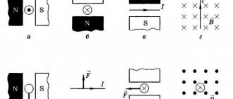
From the data presented, the force nature of the field created by alternating current or the movement of a conductor is clear. A vector expression is used to accurately express the effects on the indicator element. At the beginning of publication, such a component was the compass needle. The following shows the possibility of using a conducting frame with current.
Magnetic field lines are used to visually depict this phenomenon. If at any point of such a curve you draw a vector (B) along a tangent, it will indicate the direction of influence. Size to scale shows a certain strength.
By simply checking the geometric parameters, you can establish the uniqueness of each vector. They, like the lines of the force field, do not intersect. Below are methods for clarifying the distribution of energy flows in the conductor and the surrounding space.
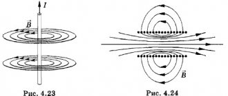
Two ways to determine the direction of a force field (electric current)
For the version with a straight conductor, the right hand is squeezed as shown in the first figure. The thumb is directed in the direction of current flow. Clenched fingers will show the direction of the lines of force. The second part of the picture demonstrates the determination of field parameters when passing current through a ring frame - the “gimlet rule”. The rotation of this tool is similar to the direction of the current.
For your information. If the solenoid is long enough, the field will be uniform over most of the working volume. It is acceptable to assume that the magnetic field lines in this case are located parallel.
What is connected with the left hand
Do not confuse the gimlet and the left hand rule; it is needed to determine the force acting on the conductor. The straightened palm of the left hand is located along the conductor. The fingers point in the direction of the flow of current I. Field lines pass through the open palm. The thumb coincides with the force vector - this is the meaning of the left hand rule. This force is called the Ampere force.
You can apply this rule to an individual charged particle and determine the direction of the 2 forces:
- Lorenz.
- Ampere.
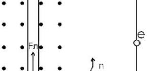
Imagine that a positively charged particle is moving in a magnetic field. The lines of the magnetic induction vector are perpendicular to the direction of its movement. You need to place your open left palm with your fingers in the direction of the movement of the charge, vector B should penetrate the palm, then the thumb will indicate the direction of vector Fa. If the particle is negative, the fingers point against the direction of the charge.
If any point was unclear to you, the video clearly shows how to use the left-hand rule:
It is important to know! If you have a body and a force acts on it that tends to turn it, turn the screw in that direction and you will determine where the moment of force is directed. If we are talking about angular velocity, then the situation here is like this: when the corkscrew rotates in the same direction as the rotation of the body, it will screw in the direction of the angular velocity.
Left hand rule: what can be determined by using it
Do not confuse the rules of the left hand and the gimlet - they are intended for completely different purposes. With the help of your left hand you can determine two forces, or rather, their direction. This:
- Lorentz force;
- Ampere power.
Let's try to figure out how it works.
Application for Ampere power
Ampere forces, what is it?
The first rule of the left hand is associated with the power of Andre-Marie Ampère, which the French scientist discovered in 1820 - immediately after Ampère’s law. The principle of its operation is as follows:
- Place your left palm so that the magnetic field induction lines enter into its inner side perpendicular to it;
- Direct all fingers, except the thumb, through the electric current
- In this case, your left thumb, which should form a right angle with the rest, will show the direction of the force that will act from the magnetic field on the current-carrying conductor - that is, the Ampere force.
However, this is only one version of PLR.
Lorentz force application and formula
The action of electromagnetic fields gives rise to the appearance of a point charged particle, which is affected by forces of an electric and magnetic nature. In their combined form they are called the Lorentz force.
Thus, the Lorentz force acts on any particle with a charge falling with a certain speed in a magnetic field. The degree of influence is related to the electrical charge of the particle (q), the magnetic induction index (B) and the speed of the particle's fall (V).
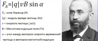
Based on the data obtained, the Dutch scientist Hendrik Lorenz derived the formula: FL = |q|x V x B x sinα. All symbols are shown in the figure.
In practical activities, the Lorentz force has been used in the following areas:
- Cinescopes are cathode ray or television tubes. In these devices, electrons flying towards the screen are deflected by a magnetic field created by special coils.
- Mass spectrographs. The masses of charged particles are determined by dividing them according to their specific charges. The vacuum chamber is placed in a magnetic field. Charged particles accelerate, move in an arc and leave a mark on the photographic plate. At the radius of the trajectory, the specific charge is first determined, on the basis of which the mass of the particle is calculated.
- Cyclotron. Accelerates charged particles. Acceleration occurs under the influence of the Lorentz force, after which the trajectory of the particles is maintained due to the magnetic field. The device has long been used in medical research using radionuclide pharmaceuticals.
- Magnetron. A high-power electron tube for generating microwaves generated by the interaction of an electron flow and a magnetic field. Used with modern radar devices.
We recommend reading: What is a zener diode used for and how does it work?
Image of magnetic induction lines
To visually study the distribution of the field in space, the dimensions of the measuring elements are reduced. Iron filings evenly scattered on the surface of a cardboard sheet or other electrically neutral plane are suitable for the experiment.
Magnetic induction lines - a visual representation of the force field distribution
If you bring a magnet from the reverse side, metal particles, like miniature compass needles, are distributed along the force strips. By the distance between them one can judge the energy parameters of the field in a certain place. Create a drawing in the same way. Greater density (near the poles) indicates an increased value of induction.
For your information. Physically separating a permanent magnet into parts will not create separate poles. This is a fundamental difference from electrostatic charges of a certain polarity, which also create a force field.
The presented knowledge is used to solve various engineering problems. In particular, simple rules for determining the direction of current in a conductor and the direction in which the solenoid core moves are useful.
Magnetic levitation train accelerates to high speeds with minimal energy losses