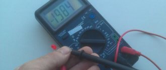
Description of the most common faults in automotive electrical equipment, types of breakdowns, diagnosis and repair. Video about malfunctions.
It is known that without fuel, a car running on an internal combustion engine will not go far. But also without electricity, which the car needs not only to recharge the smartphone, but also to simply start the engine and create sparks in the spark plugs. Why it sometimes disappears and where to look for it then is the topic of this review.
Types of car electronics breakdowns
The car's power supply system is not simple and includes many “gadgets” that influence each other. Therefore, it can be difficult to accurately determine the cause of insufficient voltage in the on-board network without special diagnostics. Signs that indicate one problem in this area may also indicate another type of problem.
And there are many examples of such problems: from a burnt-out light bulb to a short circuit in the wiring that led to a fire. In principle, malfunctions of the electrical equipment of a machine can be divided into four groups depending on the type of the failed part:
- sources of electricity: battery, generator;
- current consumers: electric drives, lighting and sound equipment, ABS;
- devices that control vehicle electronics;
- electrical wiring of the machine.
Who draws up the act
The preparation of this document takes place with the participation of a specially created commission, which includes several people (at least two). It must include a specialized specialist (foreman, technician, engineer, etc.), as well as employees who are directly related to the equipment and who are able to establish the fact of its malfunction and describe the events preceding the breakdown. If necessary, experts from third-party organizations can be involved in investigating the circumstances of the breakdown.
Diagnostics and repair
- multimeters;
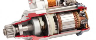
- specialized stands for testing generators or starters;
- computer auto scanners.
Moreover, for devices such as windings and coils related to relays or electric motors, three common vulnerabilities can be identified:
- open circuit - determined using a multimeter or a test lamp connected to the power source and the part being tested;
- interturn contact, to identify which the resistance at the winding terminals is measured and compared with its nominal value;
- “ground fault”, a sign of which is the electrical connection detected by the multimeter between one of the contacts of the part being diagnosed and the “ground”.
By the way, finding out what exactly is broken in the on-board network is sometimes more difficult than repairing it. Perhaps many car enthusiasts are able to replace a light bulb in a car or repair a generator with their own hands. But understanding a tangled electrical circuit is often difficult even for an experienced technician.
If the cause of the malfunction of the on-board network is not fully understood or the repair seems very difficult, then it is better to contact a car service center. And if we talk about the main malfunctions of electrical equipment, then first of all it is worth examining those that relate to one of the most significant devices for a car - the battery.
Battery faults
- rapid depreciation of the battery due to under- or overcharging, which may be a consequence of improper operation of the voltage regulator;
- self-discharge of the battery due to a decrease in the amount of active mass inside it;
- oxidation of contacts, which can cause a break in the electrical circuit between the battery and other vehicle equipment;
- Damage to the battery crankcase through which electrolyte leaks.
When checking the health of a battery, a multimeter is usually used. In addition, a hydrometer determines the density of the electrolyte in the containers, and using a load plug, the ability of the battery to operate with a connected energy consumer is determined.
Malfunctions in electrical wiring
If the protection works unexpectedly and without any reason, you will have to turn off all devices and only then turn on the protective devices. If the fault occurs again, you will have to look for the fault in the electrical wiring. First, you should check the fuses - maybe the whole problem is only in them. Or re-enable automatic protection on the electrical panel.
Malfunctions in electrical wiring can be the result of a whole chain of causes and their consequences. For example:
- due to loosening of the contact clamp in the power cord connector in one of the electrical appliances;
- The fuse may have blown due to a short circuit in one of the electrical appliances.
It should be remembered that replacing a blown fuse or re-enabling automatic protection can only be done after eliminating the cause that caused the short circuit.
Damage to electrical wiring is usually caused by current overload due to faulty protection. The main causes of short circuits are:
- damage to the insulation of current-carrying conductors and device elements,
- their unreliable fastening and connection to each other or to grounded heating, gas and water supply pipes, to the housings of grounded appliances.
Problems with the generator
The battery and generator set are largely dependent on each other, so failure of one of these devices can have a very negative impact on the operation of the other. So, if the power plant stops producing current, then the only source of electricity for the machine remains the battery. When its resource is exhausted, the car will “freeze” completely.
Problems with the generator can be determined by unusual noise, which is caused by wear of the bearings and slip rings, as well as deformation of the fasteners that fix the unit in place. The main malfunctions of this unit include:
- excessive tension, loss of elasticity or breakage of the drive belt;
- severe wear of brushes and lamellas due to long work or difficult operating conditions;
- bearing scattering due to lack of lubrication or poor quality of parts;
- problems with the windings: open circuits, turn-to-turn short circuits or ground faults;
- failure of rectifier diodes due to their poor quality or increased voltage in the vehicle network.
Problems associated with generators can be identified during diagnostics by drawing an oscillogram of the output voltage. A motor tester is usually used for this.
How to find a defect
To find electrical wiring faults, you can use the method of isolating suspected areas from the general diagram based on the apparent consequences and the reasons that could cause them.
In this case, those that can be verified by simple means should be checked first.
The ends of the wires coming out of the channels of building structures have a reserve, which allows, after a break at the end, to re-strip the insulation once or twice to strengthen the wires in the contact clamp.
If, after a break, the electrical wire does not reach the clamp, it must be extended with a piece of another wire.
It should be remembered that the connection of copper conductors is carried out by soldering; aluminum conductors can be connected by a tube with screw terminals at the ends. The tube must be steel with an anti-corrosion coating. The places of such connections are insulated with vinyl chloride pipe or electrical tape.
Damage to electrical wiring is usually caused by mechanical influences - tight entry and exit of plugs from sockets. To find electrical wiring faults, you can use the method of isolating suspected areas from the general diagram based on the manifested consequences of the reasons that could cause them.
The reason for the failure of the electrical wiring is that the electrical sockets are installed permanently in the apartment, and each electrical appliance is equipped with plugs individually. Therefore, you need to ensure that the plug and socket are of the same design.
Portable AC power receivers should be powered from a mains voltage no higher than 380/220 V. Old plug connector sockets with new plugs do not create reliable contact due to the lack of a spring part (groove) on the plugs. If an old-style plug is plugged into a modern-style socket, the sockets of the socket will be compressed by the cut pins of the plug. Repeated use of such a plug will become dangerous due to poor contact connection.
Considering that all modern household appliances are equipped with a new type of plug and the relatively low cost of sockets, you should abandon the use of old plug connectors or use splitter plugs (so-called “tees”).
In addition, in some foreign-made devices, the design of the forks differs from domestic ones (flat pins, etc.). To use them, you need to purchase special adapter devices (if they were not included in the equipment package).
Damage to electrical wiring is usually caused by switching on faulty electrical appliances. If plugging an electrical appliance into the network caused an immediate shutdown of the protection, then most likely this device is faulty.
If the protection works unexpectedly and without any reason, you will have to turn off all electrical appliances and only then turn on the protective devices. If they are triggered again, the fault will have to be looked for in the electrical wiring.
Breaks often occur even in flexible power cords of electrical devices at their exit from the plug or device body. In these sections of the cord, inside its insulation, an electric arc can occur, which can cause burn-through of the insulation and a short circuit.
Overloading the wiring wires with current from turning on devices that consume power exceeding the design rating for the wiring can cause it to catch fire. Therefore, the serviceability of protective devices is the most important condition for the safe operation of electrical wiring.
If a chandelier or ceiling light suddenly goes out, malfunctions may occur for the following reasons:
- the ends of the wires shorted and the fuses blew out - for this reason the chandelier went out;
- however, the chandelier could also go out due to a burnt-out light bulb;
- a break in the electrical wiring circuit at the point where the wires exit the ceiling channel of the chandelier due to its frequent swinging when wiping off dust or when changing electric lamps.
"The starter is stuck"
At one time, Vladimir Vysotsky sang that if “the starter is stuck,” then it is “not driving, but fidgeting.” In principle, a car can be started even with a broken starter, but only with a pusher or tow.
How well the electric starter is working can be determined by its amperage and the rotational speed of the shaft of this part at idle speed. Basic starter problems:
- formation of carbon deposits on the contacts of the traction relay and jumper;
- deformation, oxidation of the armature collector or the appearance of plaque on it;
- contact of the winding: on the armature frame - with the “ground”, on the collector - between the turns;
- severe wear of the brushes or their damage;
- jamming of brushes on the mounts due to breakage or layers.
Problems with the ignition system
About 10-12% of car electrical faults relate to the ignition system. And in 80% of cases, such problems lead to an increase in fuel consumption by 5-6%, as well as a decrease in engine power, which can simply stall while driving. Which car owner would like this?
The most typical failure of the ignition system is the absence of a spark at the spark plug. But others are not excluded:
- violation of insulation of high-voltage wires;
- burnout of spark plug tips or the appearance of deposits on them;
- the appearance of plaque on the spark plug cone;
- damage to the spark plug insulator;
- open circuit in the 12-volt circuit supplying the breaker and the primary winding of the ignition coil.
The state of the ignition system can be judged by the operating parameters of its spark plugs or the primary voltage on the coil, to determine which an oscilloscope and a motor tester are used. Repair of this complex consists of replacing faulty parts and repairing damaged contacts.
External signs of electrical equipment malfunction
External signs of electrical wiring faults is the blowing of fuses or automatic protective devices and the appearance of a specific smell of burnt insulation, sometimes sparking or overheating of the wiring.Damage to electrical wiring and its elements can occur due to careless or careless handling, as a result of poor quality installation work, or physical wear and tear of wires and cables.
When maintaining internal electrical wiring, check Loose and loose wires and cables are tightened and securely fastened. If damaged rollers, insulators, insulating tubes, porcelain funnels and bushings are found, they are immediately replaced with others. Damaged sections of wiring are replaced with new ones. If the insulation is damaged! wires, it is allowed to isolate the damaged section of the wiring with adhesive insulating tape or a tube made of insulating material.
When renovating a room, it is not allowed to cover the wiring with lime, whitewash or paint over it, since water and paint solvents coming into contact with the wires will deteriorate their insulation, which can lead to a short circuit. Water penetrates cracks, is absorbed into hygroscopic materials, mixes with dirt, dissolves acids and alkalis, forming electrolytes. The latter destroy not only insulating materials, but also metals.
It is not allowed to cover wires with carpets, curtains, curtains or other flammable materials. Do not hang wires on nails or pull them back with wire or rope.
Electrical wiring and its elements are periodically inspected and checked. The number of periodic inspections of electrical wiring depends on its design and characteristics of the room. Any malfunctions, defects, or damages identified during inspection are corrected immediately.
Electrical installation devices
Electrical installation devices include:
sockets, switches, plugs, sockets, fuses, etc.
Malfunctions of electrical installation devices.
A typical malfunction of switches is mechanical jamming of the lever or key. When inspecting the switch, broken contact springs, burnt contact plates, broken plastic parts, and cracks in the bases and covers may be found. As a rule, such switches cannot be repaired and are replaced with new ones.
In plug sockets, over time, the springs that compress the contact sockets weaken, as a result of which the plug connection heats up, the contacts become covered with soot and melt. For reliable operation of the plug connection, it is necessary to compress or replace the springs and ensure contact in which the pins of the plugs are held tightly in the sockets of the socket. If there are no spare compression springs, or if there are cracks or chips in the base and cover, the sockets must be replaced.
If you pull the plug from the hidden socket, it may fall out of the box along with the wires. You can insert it back only after first disconnecting the power supply. When securing the socket in the box, you must ensure that the wires do not get caught under the spacer tabs. The screws for securing the legs are screwed in alternately and evenly.
Using tees. Sometimes several powerful electrical appliances are connected to one outlet through a tee-splitter. This is not recommended, since a large load on the wires leading to the socket leads to overheating of the latter and rapid drying of the insulation.
Incandescent lamps
The most common malfunction of the lighting network is a burnt out light bulb. To test an incandescent lamp, you must use a known-good lamp. If such a replacement does not give a positive result, the reason should be sought in the cartridge. It is necessary to check whether the base is in contact with the central contact. If necessary, you need to bend it a little. If the base-socket contact is poor, the lamp base can be welded to the socket, causing overheating of the lamp socket, lamp and supply wires. If there are mechanical breakdowns of the contact posts, burnt plastic cases, cracks or chips, the cartridge must be replaced with a known good one.
Incandescent lamps often do not turn out of the socket The use of great force usually leads to tearing off the base. In this case, it is necessary to turn off the power supply by unscrewing the safety plugs or turning off the circuit breakers. Then, carefully rotating the lamp bulb, tear off the wires on which it hangs. Use pliers to turn out the lamp base remaining in the socket. In cases where it is not possible to unscrew the base, the cartridge is disassembled.
When reloading a cartridge, it is necessary to carefully terminate the wires. After stripping the insulation, the stranded wire is twisted so that there are no wires sticking out to the sides. Then a ring is formed using round pliers; it is advisable to tin the ring. The place where the insulation is stripped and the wire up to the ring is wrapped with insulating tape. Proper recharging is also necessary when connecting wires and cords to household electrical appliances. In the case of careless termination of the wires, a short circuit may occur between the protruding conductors, or it is enough for one wire from the ring to touch the outer parts of the fittings so that when touching them a person will become energized.
Luminaires with fluorescent lamps
Fluorescent lamps are a complex device with many structural elements and a large number of contacts. Therefore, problems with the operation of lamps can be very diverse. Possible malfunctions in the operation of fluorescent lamps and methods for eliminating them are given in table. 38.
Fluorescent lamps are removed from their sockets with great care so as not to damage the base or break the glass of the lamp, since the lamp contains mercury vapor, which is very toxic.
When operating fluorescent lamps, you need to know that the nature of the gas discharge is largely determined by the pressure of the gas or vapor in which the discharge occurs. As the temperature drops, the vapor pressure in the lamp drops and the process of ignition and combustion of the lamp deteriorates, and at temperatures below 5°C the lamp does not ignite at all.
The optimal operating temperature for fluorescent lamps is 20-25″ C.
Maintenance of lighting fixtures is usually carried out simultaneously with maintenance of electrical wiring.
Table 38. Possible malfunctions in luminaires with fluorescent lamps, causes and methods for eliminating them
Malfunction
Cause
Fault detection method
Troubleshooting method
The lamp does not light up
The lamp does not light up There is no glow at the ends of the lamp
There is no voltage on the lamp socket on the mains side, the mains voltage is low
Poor contact between the lamp pins and the socket contacts or between the starter pins and the starter holder contacts Lamp malfunction, broken or burnt filaments Starter malfunction - the starter does not close the filament circuit of the lamp cathodes Malfunction in the electrical circuit of the lamp
Malfunction of ballasts (ballast control equipment)
Check with an indicator or voltmeter the presence and magnitude of voltage Move the lamp and starter in their holders to the sides
Install a known-good lamp. There is no light in the starter.
Check all connections in the diagram
If wire breaks, contact connections are broken and
Check the power supply and ensure normal voltage Ensure good contact
Replace the lamp Replace the starter
Eliminate detected faults Replace ballasts
The lamp does not light up. The ends of the lamp glow
The lamp flashes but does not light up, there is a glow at one end
The lamp does not blink and does not light up, there is a glow at both ends of the electrode The lamp blinks and does not light up
When the lamp is turned on, an orange color is observed at its ends.
Errors in the circuit; short circuit in the circuit or socket that short-circuits the lamp; shorting the terminals of the lamp electrodes
Error in the circuit, starter malfunction (breakdown of the capacitor to suppress radio interference or sticking of the starter contacts) The starter is faulty; errors in the circuit; low mains voltage; loss of lamp electrode emission
The lamp is faulty, air has entered the lamp
no errors were found in the circuit, then the ballast is obviously faulty. Remove the starter, the glow at both ends will stop. The lamp is removed and inserted into the lamp, swapping the ends of the lamp. If a previously non-luminous electrode glows, then the lamp is working. There is no glow at the same end of the lamp. Install a working starter.
Check the network voltage with a voltmeter
Check if there is a short circuit in the cartridge on the side of the non-luminous electrode. If no short circuit is detected, check the wiring diagram Replace the lamp
Replace starter; replace the lamp; ensure normal mains voltage Replace the lamp
glow, after a while the glow disappears and the lamp does not light up. The lamp alternately lights up and goes out.
When the lamp is turned on, the spirals of its electrodes burn out
The lamp lights up, but after a few hours of operation blackening of its ends appears
The lamp lights up, when it burns, the discharge cord begins to rotate and moving spiral and serpentine stripes appear
Malfunction of the ballast (insulation or turn-to-turn short circuit in the winding is broken), there is a short circuit to the housing in the electrical circuit
Short circuit to the luminaire body in the electrical circuit Faulty ballast
The lamp is faulty; strong fluctuations in network voltage, loose contacts; the lamp covers the magnetic field lines of the ballast leakage
Carry out a thorough inspection of the electrical circuit; check the insulation of the wiring in relation to the body of the lamp Check the insulation of the wiring Using an ammeter, check the value of the starting and operating current
Replace the lamp, if the blinking continues, then replace the starter. Replace the ballast, eliminate the short circuit.
Eliminate short circuit to the housing. If the current exceeds normal values, replace the ballast. Replace the lamp; check the network voltage; check contact connections; replace ballast
Maintenance work on luminaires includes
- checking the fastening, condition of hooks and brackets;
- checking the compliance of the power of installed lamps;
- checking the condition of the insulation of wires at the places where they enter the lamps and at the places where they are terminated;
- removing dust and dirt from fixtures;
- removing glass and electric lamps and washing them;
- replacement of glass with cracks and chips;
- removing the cartridge body, cleaning contacts, tightening loose clamps;
- inspection of the condition of lighting fixtures and replacement of faulty parts;
- painting metal parts of fittings.
All types of work are carried out with the voltage turned off.
Connecting cords and plugs
Cord faults. Most often, during operation, the connecting cord of the electrical receiver wears out and is damaged. The main malfunctions of connecting cords are kink or breakage of conductor strands, as well as insulation failure, which can result in a short circuit. Therefore, before each turn on, check the condition of the insulation and braiding of the cord, especially at the points where it enters the plug, plug connector or device. The cord or flexible wire should not be twisted, no knots, twists, etc. should form on it. In such places, the cord insulation quickly wears out and the current-carrying conductors are exposed. Exposed areas of the cord are carefully insulated. If there are a lot of bare places, then the cord is completely replaced.
Breakage of current-carrying wires along the length is eliminated by recharging the cord. To do this, the cord at the point where the wire is broken or broken is cut at intervals of 10-20 mm, the wires are stripped and connected. Each core is insulated separately, and then a general insulation is applied. If the cord is damaged at the point of entry into the electrical appliance, the end of the cord with slip rings is shortened by 60-80 mm, the ends of the cord are stripped of insulation to a length of 20-25 mm and slip rings are made, which are then preferably tinned. The ends of the cord with slip rings are covered over a length of 10 mm with insulating tape so that the ring protrudes from the insulation, after which the cord is connected to the device.
Typical plug faults are
- breakage (break) of the cord when entering the plug body;
- unreliable contact of the terminated wire with the contact pin;
- oxidation and corrosion of the contact pin.
Apartment shields
When inspecting apartment panels, it is necessary to pay attention to the condition of the contacts at the places where the wires are connected. An unreliable connection leads to heating and burning of the contact, destruction of insulation and sparking. Such contacts are cleaned of soot and tightened tightly.
Circuit breakers, PAIRS and fuse links must match the loads and cross-sections of wires and cables. Protection devices with damaged housings cannot be repaired and must be replaced with new ones.
Apartment panels with cabinets must have working locks and reliable door seals. It is not permitted to store foreign objects in these cabinets.
Electric meters must not have damage to the housing, sight glasses, terminal covers, etc. Two seals are installed on the meter: one on the screws securing the meter casing, the other on the terminal cover when installing or replacing the meter.
The serviceability of the counter can be determined by the rotation of its disk. When turned off, the meter disk should stop after completing no more than one revolution. If the disk continues to rotate after turning off all pantographs, then the meter should be removed and rechecked at the relevant organizations. If the meter turns out to be in good working order, but the disk continues to rotate when the load is turned off, this means that the insulation of the electrical conductor is damaged and there is a significant current leakage. In this case, it is necessary to stop using electricity, determine the location of the damage to the wiring and eliminate power leakage.
The operation of electrical wiring with increased leakage currents is dangerous from a fire point of view (the building may catch fire), and from the point of view of electrical safety, since the damp walls of the building may be energized.
You can determine the correctness of the meter reading at home. To do this, turn off all lamps, heating devices and other consumers. For 10-15 minutes, turn on one consumer with a known power, for example an electric lamp, and determine the actual electricity consumption, which should coincide with the meter readings, taking into account the latter’s error.
External signs of a meter overload are a specific smell of burnt insulation, abnormal humming of the meter, and yellowing of the glass viewing window.
The buzzing of the meter, if it is not accompanied by self-propelling, is not a sign of its malfunction.
Triggering of protective equipment occurs due to short circuits in electrical wiring and current collectors or due to overload.
To quickly and accurately determine the location of the fault, they use the method of sequential connection of loads. To do this, turn off all electrical receivers. Replace the burnt plug, turn on the STEAM or circuit breaker. If the protection is triggered again immediately, the most likely location of the short circuit is the electrical wiring or plug socket. If the protection does not operate immediately, then turn on the lighting devices one by one, then other current collectors until a short circuit occurs. In lamps, damage most often occurs in the sockets. In the case when the protection is triggered some time after the load is turned on, it is necessary to turn off some of the electrical receivers (reduce the load), since in this case the network load exceeds the protection trip current.
You cannot install wire jumpers (bugs) instead of the factory plug, as they do not burn out even at high currents, as a result of which the insulation may catch fire and a fire may occur.
Before connecting any household electrical appliance to the network, make sure Do not connect devices to the network that do not match the network voltage. Before connecting a new device to the network, you should pay attention to the current or power they consume and calculate whether the fuses and wiring will withstand the inclusion of these devices.
Preventative testing of electrical wiring
During testing, the integrity of the cores and the correct phasing are checked - the phase connection to the switch and to the central contact of the cartridge.
At least once every three years, the insulation of the electrical wiring The lowest insulation resistance is 0.5 MOhm. If the resistance is less than 0.5 MOhm, then it is necessary to determine the cause and correct the damaged part of the wiring.
Typical malfunctions of electrical equipment and methods for eliminating them
External signs of electrical wiring malfunction are blown fuses or automatic protective devices and the appearance of a specific smell of burnt insulation, sometimes sparking or overheating of the wiring.
Damage to electrical wiring and its elements can occur due to careless or careless handling, as a result of poor quality installation work, or physical wear and tear of wires and cables.
When maintaining internal electrical wiring, check the condition of wires and cables and their insulation, tension and fastening of wires on rollers and insulators. Loose and loose wires and cables are tightened and securely fastened. If damaged rollers, insulators, insulating tubes, porcelain funnels and bushings are found, they are immediately replaced with others. Damaged sections of wiring are replaced with new ones. If the insulation of the wires is damaged, it is permissible to insulate the damaged section of the wiring with adhesive insulating tape or a tube made of insulating material.
When renovating a room, it is not allowed to cover the wiring with lime, whitewash or paint over it, since water and paint solvents coming into contact with the wires will deteriorate their insulation, which can lead to a short circuit. Water penetrates cracks, is absorbed into hygroscopic materials, mixes with dirt, dissolves acids and alkalis, forming electrolytes. The latter destroy not only insulating materials, but also metals.
It is not allowed to cover wires with carpets, curtains, curtains or other flammable materials. Do not hang wires on nails or pull them back with wire or rope.
Electrical wiring and its elements are periodically inspected and checked. The number of periodic inspections of electrical wiring depends on its design and characteristics of the room. Any malfunctions, defects, or damages identified during inspection are corrected immediately.
Electrical installation devices include: sockets, switches, plugs, sockets, fuses, etc.
Malfunctions of electrical installation devices.
A typical malfunction of switches is mechanical jamming of the lever or key. When inspecting the switch, broken contact springs, burnt contact plates, broken plastic parts, and cracks in the bases and covers may be found. As a rule, such switches cannot be repaired and are replaced with new ones.
In plug sockets, over time, the springs that compress the contact sockets weaken, as a result of which the plug connection heats up, the contacts become covered with soot and melt. For reliable operation of the plug connection, it is necessary to compress or replace the springs and ensure contact in which the pins of the plugs are held tightly in the sockets of the socket. If there are no spare compression springs, or if there are cracks or chips in the base and cover, the sockets must be replaced.
If you pull the plug from the hidden socket, it may fall out of the box along with the wires. You can insert it back only after first disconnecting the power supply. When securing the socket in the box, you must ensure that the wires do not get caught under the spacer tabs. The screws for securing the legs are screwed in alternately and evenly.
Using tees. Sometimes several powerful electrical appliances are connected to one outlet through a tee-splitter. This is not recommended, since a large load on the wires leading to the socket leads to overheating of the latter and rapid drying of the insulation.
Incandescent lamps
The most common malfunction of the lighting network is a burnt out light bulb. To test an incandescent lamp, you must use a known-good lamp. If such a replacement does not give a positive result, the reason should be sought in the cartridge. It is necessary to check whether the base is in contact with the central contact. If necessary, you need to bend it a little. If the base-socket contact is poor, the lamp base can be welded to the socket, causing overheating of the lamp socket, lamp and supply wires. If there are mechanical breakdowns of the contact posts, burnt plastic cases, cracks or chips, the cartridge must be replaced with a known good one.
Incandescent lamps often do not turn out of the socket because the base is rusty or the central contact is welded. The use of great force usually leads to tearing off the base. In this case, it is necessary to turn off the power supply by unscrewing the safety plugs or turning off the circuit breakers. Then, carefully rotating the lamp bulb, tear off the wires on which it hangs. Use pliers to turn out the lamp base remaining in the socket. In cases where it is not possible to unscrew the base, the cartridge is disassembled.
When reloading a cartridge, it is necessary to carefully terminate the wires. After stripping the insulation, the stranded wire is twisted so that there are no wires sticking out to the sides. Then a ring is formed using round pliers; it is advisable to tin the ring. The place where the insulation is stripped and the wire up to the ring is wrapped with insulating tape. Proper recharging is also necessary when connecting wires and cords to household electrical appliances. In the case of careless termination of the wires, a short circuit may occur between the protruding conductors, or it is enough for one wire from the ring to touch the outer parts of the fittings so that when touching them a person will become energized.
Luminaires with fluorescent lamps
Fluorescent lamps are a complex device with many structural elements and a large number of contacts. Therefore, problems with the operation of lamps can be very diverse. Possible malfunctions in the operation of fluorescent lamps and methods for eliminating them are given in table. 38.
Fluorescent lamps are removed from their sockets with great care so as not to damage the base or break the glass of the lamp, since the lamp contains mercury vapor, which is very toxic.
Table 39. Possible malfunctions in luminaires with fluorescent lamps, causes and methods for eliminating them
When operating fluorescent lamps, you need to know that the nature of the gas discharge is largely determined by the pressure of the gas or vapor in which the discharge occurs. As the temperature drops, the vapor pressure in the lamp drops and the process of ignition and combustion of the lamp deteriorates, and at temperatures below 5 °C the lamp does not ignite at all.
The optimal operating temperature for fluorescent lamps is 20–25 C.
Maintenance of lighting fixtures is usually carried out simultaneously with maintenance of electrical wiring.
Maintenance work on luminaires includes the following operations:
• checking the fastening, condition of hooks and brackets;
• checking the compliance of the power of installed lamps;
• checking the condition of the insulation of wires at the places where they enter the lamps and at the places where they are terminated;
• removal of dust and dirt from fixtures;
• removing glass and electric lamps and washing them;
• replacement of glass with cracks and chips;
• removing the cartridge body, cleaning contacts, tightening loose clamps;
• inspection of the condition of lighting fixtures and replacement of faulty parts;
• painting of metal parts of fittings.
All types of work are carried out with the voltage turned off.
Connecting cords and plugs
Cord faults. Most often, during operation, the connecting cord of the electrical receiver wears out and is damaged. The main malfunctions of connecting cords are kink or breakage of conductor strands, as well as insulation failure, which can result in a short circuit. Therefore, before each turn on, check the condition of the insulation and braiding of the cord, especially at the points where it enters the plug, plug connector or device. The cord or flexible wire should not be twisted, no knots, twists, etc. should form on it. In such places, the cord insulation quickly wears out and the current-carrying conductors are exposed. Exposed areas of the cord are carefully insulated. If there are a lot of bare places, then the cord is completely replaced.
Breakage of current-carrying wires along the length is eliminated by recharging the cord. To do this, the cord at the point where the wire is broken or broken is cut at intervals of 10–20 mm, the wires are stripped and connected. Each core is insulated separately, and then a general insulation is applied. If the cord is damaged at the point of entry into the electrical appliance, the end of the cord with slip rings is shortened by 60–80 mm, the ends of the cord are stripped of insulation to a length of 20–25 mm and slip rings are made, which are then preferably tinned. The ends of the cord with slip rings are covered over a length of 10 mm with insulating tape so that the ring protrudes from the insulation, after which the cord is connected to the device.
Typical plug faults are:
• breakage (kink) of the cord when entering the plug body;
• unreliable contact of the terminated wire with the contact pin;
• oxidation and corrosion of the contact pin.
When inspecting apartment panels, it is necessary to pay attention to the condition of the contacts at the places where the wires are connected. An unreliable connection leads to heating and burning of the contact, destruction of insulation and sparking. Such contacts are cleaned of soot and tightened tightly.
Circuit breakers, PAIRS and fuse links must match the loads and cross-sections of wires and cables. Protection devices with damaged housings cannot be repaired and must be replaced with new ones.
Apartment panels with cabinets must have working locks and reliable door seals. It is not permitted to store foreign objects in these cabinets.
Electric meters must not have damage to the housing, sight glasses, terminal covers, etc. Two seals are installed on the meter: one on the screws securing the meter casing, the other on the terminal cover when installing or replacing the meter.
The serviceability of the counter can be determined by the rotation of its disk. When turned off, the meter disk should stop after completing no more than one revolution. If the disk continues to rotate after turning off all pantographs, then the meter should be removed and rechecked at the relevant organizations. If the meter turns out to be in good working order, but the disk continues to rotate when the load is turned off, this means that the insulation of the electrical conductor is damaged and there is a significant current leakage. In this case, it is necessary to stop using electricity, determine the location of the damage to the wiring and eliminate power leakage.
The operation of electrical wiring with increased leakage currents is dangerous from a fire point of view (the building may catch fire), and from the point of view of electrical safety, since the damp walls of the building may be energized.
You can determine the correctness of the meter reading at home. To do this, turn off all lamps, heating devices and other consumers. For 10–15 minutes, turn on one consumer with a known power, for example an electric lamp, and determine the actual electricity consumption, which should coincide with the meter readings, taking into account the latter’s error.
External signs of a meter overload are a specific smell of burnt insulation, abnormal humming of the meter, and yellowing of the glass viewing window.
The buzzing of the meter, if it is not accompanied by self-propelling, is not a sign of its malfunction.
Triggering of protective equipment occurs due to short circuits in electrical wiring and current collectors or due to overload.
To quickly and accurately determine the location of the fault, they use the method of sequential connection of loads. To do this, turn off all electrical receivers. Replace the burnt plug, turn on the STEAM or circuit breaker. If the protection is triggered again immediately, the most likely location of the short circuit is the electrical wiring or plug socket. If the protection does not operate immediately, then turn on the lighting devices one by one, then other current collectors until a short circuit occurs. In lamps, damage most often occurs in the sockets. In the case when the protection is triggered some time after the load is turned on, it is necessary to turn off some of the electrical receivers (reduce the load), since in this case the network load exceeds the protection trip current.
You cannot install wire jumpers (bugs) instead of the factory plug, as they do not burn out even at high currents, as a result of which the insulation may catch fire and a fire may occur.
Before connecting any household electrical appliance to the network, make sure that the voltage for which the device is designed corresponds to the mains voltage. Do not connect devices to the network that do not match the network voltage. Before connecting a new device to the network, you should pay attention to the current or power they consume and calculate whether the fuses and wiring will withstand the inclusion of these devices.
Preventative testing of electrical wiring
During testing, the integrity of the cores and the correct phasing are checked - the phase connection to the switch and to the central contact of the cartridge.
At least once every three years, the insulation of the electrical wiring is checked with a 500 or 1000 V megger. The insulation resistance is measured between each wire and the ground. The lowest insulation resistance is 0.5 MOhm. If the resistance is less than 0.5 MOhm, then it is necessary to determine the cause and correct the damaged part of the wiring.
ECM malfunctions
- up to 35% of breakdowns in this case occur due to wire breaks and loss of communication between sensors and the electronic control unit;
- up to 22% – problems with the fuel pump: jamming of the armature and brushes, contacts between the turns of the winding or its breakage;
- up to 9% – malfunctions associated with the electromagnetic injector wires: breakdowns, breaks, unnecessary contacts.
A good help for the vehicle owner is the vehicle’s self-diagnosis system, which records and stores information about possible malfunctions in the operation of the vehicle. With some of them, the “Check engine” indicator lights up.
The fault codes recorded by the system are read using a laptop connected to the car with a scanner or directly. A smartphone is also applicable.
Short circuit and its consequences
In June 2022, an incident occurred in the Orenburg region in which a malfunction in the electrical equipment of a machine caused it to catch fire. The fire then spread to the house, the total fire area was 150 square meters. m. As a result of the emergency, a local resident was hospitalized. Thus, a short circuit in the vehicle’s on-board network can cause damage not only to the vehicle.
Emergency specialists name a short circuit in the on-board network and a malfunction of the fuel system among the main causes of fire in the engine compartment of a car. In general, smoke, as well as the smell of burnt rubber or wiring in the car interior, can indicate a possible fire to the driver. If a fire does happen , representatives of the Ministry of Emergency Situations recommend not to panic and adhere to the following recommendations:
- park the car on a road exit, away from passers-by, buildings and other cars;
- turn off the engine, and if there were passengers in the car, they should be disembarked;
- put the car on the handbrake, pick up documents from the car;
- if the car catches fire while driving, then you should not increase the speed - this will only increase the ignition;
- if something catches fire in the engine compartment, you should use a pry bar or some kind of stick to slightly open the hood and direct foam from a fire extinguisher under it;
- if the fire approaches the fuel tank, it is better to move away from the car and take passengers away from it, if there were any;
- You should not stay inside a burning car for more than 90 seconds;
- If your car catches fire, call the fire department or rescue service.
Conclusion
Of course, malfunctions in the electrical equipment of a car do not necessarily have such serious consequences as in the case of a short circuit in the wiring. For example, with a broken smartphone charger or even an air conditioner, it is quite possible to drive for some time. The cost and complexity of repairs for such breakdowns depends on the nature of the problem. At the same time, the vehicle’s on-board network connects a variety of units that influence each other. And if any of them suddenly stops working, it is better to fix it rather than wait until something else breaks.
Video about malfunctions of the electrical equipment of the machine:
Replacing car wiring
When replacing wiring in a car, be sure to turn off the power, including disconnecting the battery. Of course, this is not a precaution against electric shock, but protection of the vehicle’s electrical equipment from possible short circuits that may occur during repair work.
Sometimes the replacement can be completed in 10-15 minutes - for example, if the wires of the “battery-generator” supply circuit are damaged. If the integrity of the wiring in the cabin is damaged, there are problems with grounding, or a short circuit in the on-board computer circuit, then the work will take much more time. And the main thing here is not to make a mistake, since incorrectly connecting the wires (for example, if the polarity is reversed) can cause a short circuit, damage to expensive electrical equipment and even a fire. If you do not have experience in electrical engineering and electrical installation work, it is better to contact a specialized service for the services of a professional auto electrician.
You can download the diagrams from here.
Before we get started, let's get acquainted with the basic principles of these schemes:
1. There are three main lines. The top red one is a conditionally constant “+” from the battery (we can say that these are two wires that go into the passenger compartment and to the starter/generator from the battery advisory terminal). The black under the aforementioned red is the “+”, from the ignition switch, which powers consumers when the key is turned to the recommended position. The bottom black one is a conditionally constant “-”, which is also the mass (car body).
2. At the bottom of the diagram you can see the labels of the electrical equipment groups in the wiring. The groups are in order of importance, i.e. start with engine systems and end with auxiliary devices. Many groups are “intertwined” with each other physically, but are placed far from each other on the diagrams. In this case, the corresponding wires on the diagrams have at their ends a designation of the coordinate where it is transferred - references. This is a rectangle with numbers in green fill.
