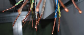
Connecting wires
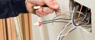
To ensure full electrical conductivity, the integrity of the wiring is an important point. Damage or poor-quality adhesion is unacceptable.
It is important to ensure tight contact contacts and reliable connections in the “electrical node” areas. There are certain methods for eliminating cable breaks.
Among them, welding should be noted. It applies to copper and aluminum wires. This ensures a particularly reliable grip.
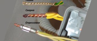
Connections can be divided into types:
- twist;
- welding;
- soldering;
- pressure testing;
- terminal blocks;
- self-clamping terminal blocks (WAGO terminals);
- PPE caps;
- bolt clamp.
The most complete connection for wires made of copper is soldering. It can be easily accomplished using flux (rosin, borax) and tin solder. Terminal blocks are also used - a special device that is made using screw terminals. They are selected separately in accordance with the cross-section of the cores.
Self-clamping terminal blocks are often used to save time on electrical installation work. In order to isolate a twisted or soldered electrical connection, PPE insulating caps are used. Today in the energy sector, WAGO terminals are widely used, which are produced for wires and cables of various diameters. In addition, WAGO terminals allow you to connect conductors made of different materials (copper and aluminum).
The choice of which connection to use depends on various factors:
- material (steel, copper, aluminum);
- number of twisted elements;
- section;
- place of work (house, street, in the ground, etc.).
How many wires can be twisted into one twist?
Currently, simple twisting of wires as a type of electrical connection is prohibited. But at the same time, it is often used for greater reliability of contact in other connection options, for example when welding conductors.
Previously, I already talked about all the permitted methods of connecting wires when installing electrical wiring. For a truly reliable and durable connection that will pass any test, be sure to choose one of these.
Now I will tell you in more detail about how many wires can be twisted together. Moreover, you will learn a simple rule, following which you can easily determine the required number of wires of any cross-section for twisting.
There are no official standards that would limit the number of wires in one twist.
And, if you wish, you can twist at least 50 cores together, but I highly do not recommend doing this, now I’ll tell you why.
Many professional electricians will tell you literally the following: “Correct twisting of copper wires when laying electrical wiring is in itself quite reliable without the use of additional clamps, welding, terminal blocks or sleeves.”
And you will definitely hear stories from practice when a distribution box is opened in an apartment that is several decades old, and the connections there are made through ordinary twists. At the same time, they, like the rest of the electrical wiring, are in close to ideal condition.
There is a simple explanation for this - correct twisting of wires implies their uniform laying, with the required force, of sufficient length, using the correct insulation, etc.
All this together gives a reliable, long-lasting contact that does not require additional revisions for pulling. As you understand, in order to do professional twisting of cable cores, you need certain experience and skills. Violation of technology leads to poor contact. Such a connection is simply dangerous; it can heat up and be a source of fire.
That is why it was decided to prohibit all twists when connecting wires. Other methods are much easier to control and forgive some errors during installation. This increases overall electrical safety.
For the same reason, there is a limitation on the number of wires that can be twisted into one twist. It is almost impossible to achieve high-quality twisting of a large number of wire strands without experience.
How to connect electrical wires with lugs
Another way is to use tips. The tip looks like a piece of tube, cut and turned flat on one side. A hole for a bolt is drilled in the flat part. The lugs allow you to connect cables of any diameter in any combination. If it is necessary to connect a copper cable to an aluminum cable, special lugs are used, in which one part is copper and the other is aluminum. It is also possible to place a washer, brass or tinned copper, between the tips.
The ferrule is pressed onto the cable using a crimper, similar to how wires are connected using crimping.
Wiring connection tool
Twisting requires a minimal set of tools. First, you need to remove the insulating layer from the cable. A knife or wire cutters are suitable for this. It is most convenient to use a special tool - a stripper. Next, the stripped wires are twisted. If the wire is single-wire, it is advisable to tighten them with pliers. The last stage is sealing the connection. To do this, you should use insulating heat-shrinkable tubes or PVC tape.
Wire Stripper
Options for twisting stranded wires
In practice, 3 methods of twisting flexible stranded wires are used. The choice of method is made according to the situation and based on the preferences of the master. The methods are:
- serial connection;
- parallel connection;
- thin wire bandage;
Serial twisting
The stripped wires are applied to each other so that they form a crosshair. Then the conductors are twisted together. The connection made is symmetrical relative to the crosshairs. The ends of the wires stick out in opposite directions. After twisting, it is advisable to slightly tighten it so that it tightens.
The method is good due to the compactness of the resulting connection. Its thickness does not exceed 3 diameters of the insulated wire. Care must be taken. If the twist is protected from moisture by a heat-shrinkable tube, then the insulation is put on the core before making the connection.
Parallel
The insulation is removed from the ends of the wires. The cores should be connected so that the stripped sections are parallel. The ends of the wires point in the same direction. The current conductors are then wound onto each other in a spiral shape
It is important to make the connection as tight as possible, but not to break the conductors with excessive force
This twist can be found in the junction box. To protect the contact, electrical tape or heat shrink is used. For temporary and non-essential connections, it is allowed to use a PVC pipe (cambric) for insulation.
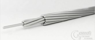
Bandage twist
The banded connection of cores is suitable for connecting thick wires that are difficult to bend with your hands or pliers. Current-carrying conductors are laid next to each other. They must first be properly cleaned on all sides using a needle file or file. Then the bare wires are tightly wrapped in a circle with the maximum number of thinner wires. A similar connection is used on power transmission towers.
Important! Do not connect the cable cores in a knot. The contact will be maximally tensile strength, but extremely unreliable in terms of electrical conductivity
Welding connection
The connection of single-core and stranded wires by welding, provided they are performed correctly, ensures maximum reliability and efficiency in electrical terms. The essence of the method is that, using a special welding machine, the current-carrying cores of the connected conductors are melted. When the metal cools, a monolithic compound is formed. In terms of its conductivity, it is not inferior to a solid conductor, since with this switching method there is no transition resistance. The connection made by welding can withstand mechanical loads well.
In this way, you can connect wires of almost any type with each other. The number of connected conductors can be any. However, it is important to know how to connect solid and stranded wire correctly. Installation by welding is performed after twisting the wires. Before twisting a stranded wire with a solid wire, it must be thoroughly cleaned. After this, the end of the stranded wire should be processed with a welding machine. At the same time, it must fuse into a single whole. After this, the conductors are twisted together and their ends are melted with a welding machine to form a reliable and high-quality connection. If installation is carried out without first melting a stranded wire, then its individual wires may burn out during welding, which will lead to a decrease in cross-section, and therefore an increase in resistance at the junction.
Sleeves
The third simple way to connect conductors is crimping with sleeves.
GML sleeves are most often used for joining copper wires. Deciphered as:
Sleeve
Copper
Tinned
For connecting pure aluminum - GA (aluminum sleeve):
To switch from copper to aluminum, special adapters GAM:
What is the crimping method? Everything is quite simple. Take two conductors and strip them to the required distance.
After this, on each side of the sleeve, the conductors are inserted inside, and the whole thing is crimped with press pliers.
Despite its obvious simplicity, there are several rules and nuances in this procedure, if not followed, you can easily ruin a seemingly reliable contact. Read about these mistakes and rules on how to avoid them in the articles “5 Rules of Crimping” and “Crimping Insulated Tips, Sleeves and Terminals”.
To work with conductors of large sections 35mm2-240mm2, a hydraulic press is used.
Up to cross-sections of 35mm2, you can also use a mechanical one with a large span of handles.
The sleeve must be crimped two to four times, depending on the cross-section of the wire and the length of the tube.
The most important thing in this work is to choose the correct sleeve size. For example, when connecting a monocore, the sleeve is usually taken to a smaller cross-sectional size.
For example, when connecting a monocore, the sleeve is usually taken to a smaller cross-sectional size.
And in this way you can connect several conductors at one point at the same time. In this case, only one sleeve will be used.
The main thing is to completely fill its internal space. If you are crimping three conductors at the same time, and you still have voids inside, then you need to “fill” this free space with additional pieces of the same wire, or with conductors of a smaller cross-section.
Only after this can you press.
After crimping, such a connection must be insulated. The most convenient way to do this is with a heat-shrinkable tube HERE.
There are tubes with an adhesive base. When heated, this glue flows out and ensures the tightness of the connection.
Insulation using a thermal tube is also a fairly simple process. In the absence of a gas burner or hair dryer, even a lighter is sufficient for small sections.
Sleeve crimping is one of the most versatile and reliable connections, especially when it is necessary to extend the cable, including the input cable.
In this case, the insulation turns out to be almost equivalent to the main one, when also using the outer tube HERE as a casing.
Connecting wires of different cross-sections
Correct twisting is done with wires of equal thickness. In reality, this is not always possible. From time to time it is necessary to connect wires of different sections. Due to the different sizes of the wires, they will not be able to press properly. Therefore, it is advisable to solder the connection or use some type of terminal block or crimp sleeves.
A common case of such twisting is a branch in the electrical panel of a phase wire to an apartment. To increase reliability, the contact is improved with a “walnut” type connector. Its more professional, but less common name is branch compression.
How many wires should be in a twist?
Most often, it is recommended to collect no more than 6 cores with a cross section of 2.5 mm2. in one twist, or better, especially if you have little experience, no more than 4 times. Cables with this cross-section are used in apartments for socket groups.
You can take more conductors with a cross section of 1.5 mm2 used for lighting. And the cables going to the electric stove have a conductor cross-section of 6 mm sq. As you understand, even six pieces are very difficult to neatly twist together without experience.
In order not to memorize the maximum number of wires recommended for twisting:
There is a simple rule:
The total cross-section of all wires in a twist should not exceed 16 mm2, and the total number of wires is 6 pieces
Standard distribution boxes most often have up to 6 cable entry points, so twisting with a large number of conductors usually does not work.
Another simple explanation for the limitation of the maximum number of cores is the following: a larger number simply will not allow the tool to properly grasp them when working.
Therefore, I recommend not twisting more than 6 wires at the same time. But, with some skill and strong hands, or using various devices, in rare cases you can twist up to 8 pieces.
Below is a table that shows the recommended maximum number of wires in one twist for different cable sections:
| Wire cross-section mm.kv | Number of wires in twist | |
| Recommended | Maximum | |
| 1.5 | 6 | 8 |
| 2.5 | 4 | 6 |
| 4 | 3 | 4 |
| 6 | 2 | 2 |
| 10 | 2 | 2 |
When making electrical installations, try to avoid cases where it is necessary to twist more wires than are recommended here.
It is always better to make an additional junction box than to get a poor-quality connection, which will then cause you a lot of problems.
And once again I would like to remind you that officially, simple twisting in electrical applications is prohibited and is used only in combination with other connection methods - compression, welding, etc.
I am sure that there are a lot of people who will say that they can easily twist a larger number of wires with high quality, and the resulting connection is as reliable as possible. I won’t argue with this; moreover, in my practice I’ve had to do something like this (I always weld conductors after twisting).
A striking example of this could be an article about extending the input cable to an apartment, where 3 wires of 6 mm square were twisted. When using certain technologies, this is possible, but I do not recommend doing this all the time; use this opportunity only as an exception.
What do you think? Tell us about your experience in installing twists and the maximum number of wires that can be done efficiently. I am especially interested in the opinion of novice electricians who have decided to do wiring in an apartment or country house.
Splicing stranded wires without twisting
Stranded wires can be spliced in the same way as single-core wires. But there is a more advanced method, in which the connection is more accurate. First you need to adjust the lengths of the wires with a shift of a couple of centimeters and strip the ends to a length of 5-8 mm.
Fluff the slightly cleaned areas of the pair to be joined and insert the resulting “panicles” into each other. In order for the conductors to take a neat shape, they need to be tied together with a thin wire before soldering. Then lubricate with soldering varnish and solder with solder.
All conductors are soldered. We clean the soldering areas with sandpaper and insulate them. We attach one strip of electrical tape on both sides along the conductors and wind a couple more layers.
This is what the connection looks like after covering it with insulating tape. You can further improve the appearance if you use a file to sharpen the solder joints on the insulation side of adjacent conductors.
The strength of connected stranded wires without twisting by soldering is very high, as the video clearly demonstrates. As you can see, the connection can withstand the weight of the monitor 15 kg without deformation.
Connecting wires with a diameter of less than 1 mm by twisting
Let's consider twisting thin conductors using the example of splicing twisted pair cables for computer networks. For twisting, thin conductors are stripped of insulation for a length of thirty diameters with a shift relative to adjacent conductors and then twisted in the same way as thick ones. The conductors must wrap each other at least 5 times. Then the twists are bent in half with tweezers. This technique increases mechanical strength and reduces the physical size of the twist.
As you can see, all eight conductors are connected by twisting with a shift, which makes it possible to do without isolating each of them separately.
All that remains is to tuck the conductors into the cable sheath. Before refueling, to make it more convenient, you can tighten the conductors with a roll of insulating tape.
All that remains is to secure the cable sheath with insulating tape and the twist connection is complete.
The technology of splicing twisted pair cables is discussed in a separate article, “Lengthening twisted pair cables.”
Connecting copper wires in any combination by soldering
When connecting and repairing electrical appliances, you have to lengthen and connect wires with different cross-sections in almost any combination. Let's consider the case of connecting two stranded conductors with different cross-sections and number of cores. One wire has 6 conductors with a diameter of 0.1 mm, and the second has 12 conductors with a diameter of 0.3 mm. Such thin wires cannot be reliably connected with simple twisting.
With the shift, you need to remove the insulation from the conductors. The wires are tinned with solder, and then the smaller gauge wire is wound around the larger gauge wire. It is enough to wind a few turns. The twisting area is soldered with solder. If a direct connection of wires is required, the thinner wire is bent and then the connection is insulated.
Using the same technology, a thin stranded wire is connected to a single-core wire with a larger cross-section.
As is obvious, using the technology described above, you can connect any copper wires of any electrical circuits. At the same time, we must not forget that the permissible current strength will be determined by the cross-section of the thinnest wire.
Methods for connecting wires or cables to each other
The junction of two conductors must meet the following requirements:
- reliability;
- mechanical strength.
These conditions can also be met when connecting conductors without soldering.
Crimping
This method requires special equipment. Crimping of wires with sleeves is carried out for both copper and aluminum wires of different diameters. Depending on the cross-section and material, the sleeve is selected.
Crimping algorithm:
- stripping of insulation;
- stripping wires to bare metal;
- the wires need to be twisted and inserted into the sleeve;
- the conductors are crimped using special pliers.
Selection of a sleeve causes major difficulties. An incorrectly selected diameter will not ensure reliable contact.
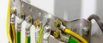
Bolted connection
Bolts, nuts and several washers are used for contact. The connection point turns out to be reliable, but the structure itself takes up a lot of space and is inconvenient to install.
The connection order is as follows:
- stripping of insulation;
- the stripped part is laid in the form of a loop with a diameter equal to the cross-section of the bolt;
- a washer is put on the bolt, then one of the conductors, another washer, a second conductor and a third washer;
- the structure is tightened with a nut.
Using a bolt, you can connect several wires. The nut is tightened not only by hand, but also by a wrench.
Terminal blocks
The terminal block is a contact plate in a polymer or carbolite housing. With their help, any user can connect wires. The connection occurs in several stages:
- stripping the insulation by 5-7 mm;
- removal of oxide film;
- installing conductors in sockets opposite each other;
- fixation with bolts.
Pros - you can connect cables of different diameters. Disadvantages - you can only connect 2 wires.
Types of terminal blocks for multi-core and single-core cables
There are 5 main types of terminal blocks:
- knife and pin;
- screw;
- clamping and self-clamping;
- cap-shaped;
- "walnut" type clamps.
The first type is rarely used; they are not designed for high currents and have an open design. Screw terminals provide reliable contact but are not suitable for connecting multi-core cables. Clamp terminal blocks are the most convenient devices to use; their installation does not require special equipment. Cap-type devices are also often used, but unlike clamping devices, caps can be used repeatedly. "Nut" is practically not used.
Terminals in junction box (copper or metal)
Terminals are the most common connection method in a junction box. They are cheap, easy to install, provide reliable contact fixation and can be used to connect copper and aluminum. Flaws:
- cheap devices are of low quality;
- Only 2 wires can be connected;
- Not suitable for stranded wires.
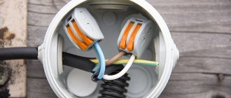
Self-clamping terminal blocks WAGO
There are 2 types of Vago terminal blocks used:
- With a flat spring mechanism - they are also called disposable, since reuse is impossible. Inside there is a plate with spring petals. When installing the conductor, the petal is pressed out and the wire is clamped.
- With lever mechanism. This is the best connector option. The stripped conductor is inserted into the terminal and the lever is clamped. Re-installation is possible.
With proper use, Vago terminal blocks last 25-30 years.
Using Tips
For connection, 2 types of tips and sleeves are used:
- in the first, the connection is made inside the product;
- in the second, two electrical wires are terminated with different tips.
The connection inside the sleeve or tip is strong and reliable. There are also special sleeves for connecting copper and aluminum wires.
Soldering of electrical wiring lugs
The tips are connected to the wiring using a press. If it is not there, contact can be ensured by soldering.
The electrical wire and the tip inside are tinned, the stripped cable is inserted inside.
The entire structure on the contact must be wrapped with fiberglass tape and heated with a burner until the tin melts.
Methods of connecting electrical wires: types of connections + technical nuances
When installing an additional outlet, connecting a new chandelier, or troubleshooting a fault in the electrical wiring, you will have to deal with electrical work.
Without practical experience, it is difficult to ensure reliable contact between conductors made of different materials, having different cross-sections or even different numbers of cores. The article we have proposed describes in detail all the methods of connecting electrical wires that are used in the construction of electrical wiring. We analyzed the technical and technological features of each option. With our advice, you can successfully repair or upgrade your electrical network.
Important Notes on Wiring Connections
Let us note important points regarding electrical wires.
- All wires twisted together should not dangle somewhere in the air! They must be placed in a junction box.
- For all wire connections, ensure that the bare ends of the wires are completely hidden in the connection block. That is, try to make the connection so that after this connection it would be impossible to reach the bare end of the wire with your hand.
- Do not try to remove the wire from terminals that are not intended for this purpose. For example, there are craftsmen who manage to remove wires from wago terminals. But I do not recommend doing this, since such removal is always associated with deformation of the wire. And this is unacceptable, because the load on the network should be experienced by whole wires, and not half-broken ones, which can lead to short circuits.
This is where the article ends. We have studied in detail the issue of how to connect wires in an apartment. Now, when moving the socket from one place to another, you can easily extend the wires by laying them in the wall and making the correct connection.
They installed these pads for me at home... It would be better if they did everything with twists. The socket doesn't work and that's it. I called an electrician, he immediately said that the problem was in the pads and that they (the problems) would appear periodically. I reached into the box and sure enough: I turned the wire in the block, the socket started working. But problems cannot help but appear: in the block the wires are pressed with thin petals, very similar to steel ones. So I'll look for something else instead of pads...
I’ll honestly tell you that I made all the connections at home through the blocks. The kitchen has a lot of electricity supply: 3 sockets, heated floor. dishwasher, hood, microwave and everything is on blocks that are hidden in junction boxes or sockets.
I don’t argue that there are cases, but these are the exception rather than the rule. There might have been a defective batch. And the examples are very different. Some people's walls fall apart after plastering, while others have had no problems for 25 years. But this does not mean that now there is no need to plaster the walls. Somewhere the technology was broken. Therefore, here we need to study the problem, look deeper into why this is happening. And if twists were the most reliable, then firefighters would not prohibit them.
Hello. I am installing electrical wiring for a mini-bakery. Everything is great except for one thing. The fact is that I am opening a company in a remote corner from civilization in a small village. The city is 2000 km away and only by plane. Therefore, I stocked up on everything in advance. Except of course the wires. And then I somehow found the usual white two-wire and three-core aluminum noodles with a cross-section of 1.5 sq. mm. and copper three-core 2.5 sq. mm. Three-phase electrics. I installed 2-wire noodles for lighting, and three-wire for sockets with chargers. I have only three equipment supplying 380 W. Dough mixer 2.4 kW, Flour sifter 1.2 kW, Oven 19.2 kW. Since there is no choice, all three of them carried out wiring with a cross-section of 2.5 sq. mm. In addition to the stove, the dough mixer and flour sifter work perfectly. But when I turn on the stove after 5 minutes, the RCD 63A 30Ma turns off the electrical supply. I think this is due to the cross-section of the wire because... I found on the instructions that you need to use a wire with a cross-section of 6 sq. mm. How can you get out of the situation? Of course it would be great to find a 6 sq. mm wire. But I only have 2.5 sq mm. Please tell me whether it is possible to use a three-core wire as one wire, i.e. connect all three to one?
Yes. It would be optimal to make all three wires of one wire 1 phase (7.5 sq. mm), another 3-core wire for the second phase, and also for the third phase, also for zero (also 7.5 sq. mm, respectively), and grounding. With such loads (about 60 A), no terminals will withstand (except screw ones. But for myself I wouldn’t risk it), it is necessary to twist, which should be tinned and soldered (use acid-free flux, solder and a simple gas torch + futor (copper tube with a diameter of 25mm, one end is rolled onto a holder so that the solder does not leak out, approximately 3cm deep), or a welding machine and a copper electrode (boil the ends of the twists until all the cores are welded together into a ball at the end).
How to connect wires of different sections?
It often happens that wires of different sections come into the junction box and they need to be connected. It seems like everything should be simple here, as with connecting wires of the same section, but there are some peculiarities here. There are several ways to connect cables of different thicknesses.
Remember that you cannot connect two wires of different sections to one contact in a socket, since the thin one will not be pressed tightly by the bolt. This will lead to poor contact, high contact resistance, overheating and melting of the cable insulation.
How to connect wires of different sections?
1. By twisting with soldering or welding
This is the most common way. You can twist wires of adjacent sections, for example 4 mm2 and 2.5 mm2. Now, if the diameters of the wires are very different, then good twisting will no longer work.
When twisting, you need to make sure that both wires wrap around each other. Do not allow a thin wire to wrap around a thick one. This may result in poor electrical contact. Do not forget about further soldering or welding.
Only after this will your connection work for many years without complaints.
2. Using screw clamps ZVI
I already wrote about them in detail in the article: Methods of connecting wires. Such terminal blocks allow you to insert a wire of one cross-section on one side, and a different cross-section on the other side. Here each core is clamped with a separate screw. Below is a table that will help you choose the right screw clamp for your wires.
| Screw clamp type | Cross-section of connected conductors, mm2 | Permissible continuous current, A |
| ZVI-3 | 1 – 2,5 | 3 |
| ZVI-5 | 1,5 – 4 | 5 |
| ZVI-10 | 2,5 – 6 | 10 |
| ZVI-15 | 4 – 10 | 15 |
| ZVI-20 | 4 – 10 | 20 |
| ZVI-30 | 6 – 16 | 30 |
| ZVI-60 | 6 – 16 | 60 |
| ZVI-80 | 10 – 25 | 80 |
| ZVI-100 | 10 – 25 | 100 |
| ZVI-150 | 16 – 35 | 150 |
As you can see, using ZVI you can connect wires of adjacent sections. Also remember to look at their amperage rating. The last digit in the screw terminal type indicates the amount of permissible continuous current that can flow through this terminal.
We strip the wires to the middle of the terminal...
We insert them and tighten the screws...
3. Using Wago universal self-clamping terminals.
Wago terminal blocks have the ability to connect wires of different sections. They have special sockets where each wire “sticks” into. For example, you can connect a 1.5 mm2 wire into one hole of the clamp, and 4 mm2 into the other, and everything will work properly.
According to the manufacturer's markings, terminals of different series can be used to connect wires of different sections. See table below:
| Wago terminal series | Cross-section of connected conductors, mm2 | Permissible continuous current, A |
| 243 | 0.6 to 0.8 | 6 |
| 222 | 0,8 – 4,0 | 32 |
| 773-3 | 0.75 to 2.5 mm2 | 24 |
| 273 | 1.5 to 4.0 | 24 |
| 773-173 | 2.5 to 6.0 mm2 | 32 |
Below is an example with series 222...
4. Using a bolted connection.
A bolted connection of wires is a composite connection consisting of 2 or more wires, a bolt, a nut and several washers. It is considered reliable and durable.
Here it goes like this:
- we strip the core by 2-3 centimeters, so that it is enough for one full revolution around the bolt;
- we make a ring from the core according to the diameter of the bolt;
- take the bolt and put it on the washer;
- We put a ring of conductor of the same section on the bolt;
- then put on the intermediate washer;
- put on a ring made of a conductor of a different cross-section;
- We put the last washer and tighten the whole thing with a nut.
In this way, you can simultaneously connect several wires of different sections. Their number is limited by the length of the bolt.
5. By squeezing the branch “nut”.
I wrote about this connection in detail with photographs and corresponding comments in the article: Connecting wires using nut-type clamps. Let me not repeat myself here.
6. Using tinned copper tips through a bolt with a nut.
This method is well suited for connecting large cross-section cables. For this connection, it is necessary to have not only TML tips, but also crimping pliers or a hydraulic press. This connection will be a little bulky (long), and may not fit into some small junction box, but it still has the right to life.
Unfortunately, I didn’t have a thick wire and the necessary tips on hand, so I made a photo from what I had. I think you can still understand the essence of the connection from it.
Let's smile:
Methods of connecting wires: procedure for performing the operation
Twisting is considered the most common option for fastening several conductors together. For this method, it is enough to remove the insulation from the current-carrying wires and twist them tightly together.
Important! For maximum reliability of such a connection, it is recommended to remove the insulation material by at least 5 cm. For good contact, the wires are pressed with pliers
The method of soldering two conductors takes a little longer than the previous one, but it is more reliable. The ends of the conductors are coated with tin or rosin, and then carefully soldered. Such fastening does not create much resistance in the conductors.
The welding method is similar to soldering, but requires more care and the involvement of specialists for such work.
Connection terminals are the most popular and advanced option. Similar fasteners are used in switchboard devices and distribution boxes. The convenience of the connection lies in the ability to use current-carrying conductors of various cross-sections and materials of manufacture.
Spring fasteners are not inferior to pads. The method of such a connection is no less reliable, but efficient. With this, everyone can cope with the task of connecting electrical wiring. In home improvement, the use of bolted clamps and connections is practiced. The only drawback of such fasteners is the mandatory and durable insulation. These devices are used to fasten stranded wires and conductors with different cross-sections.
Spring terminal blocks for wires of different sections
Wire Twist Tool
This task requires certain tools. Among the mandatory ones:
- pliers (described in the article);
- side cutters;
- hydraulic or manual crimpers.
Hydraulic manual press KVT “PGR-70”
You will also need a twisting attachment and insulation material. When working with these tools, it is imperative to comply with safety regulations. Certain job skills will be required. Although in some cases it is possible to twist wires protected by insulation by hand, today a wire twister is usually used. It greatly simplifies the work and guarantees high quality results. A work device such as pneumatic or hydraulic press jaws allows you to terminate conductive wires for further connection.
There are also small devices that allow you to speed up the twisting of the cores. Such a device is inserted into a screwdriver and twists them by rotating them.
Twisting devices
Connection between 6 wires
YOU'RE LYING!!!
In fact, INSULTING the members of the forum who have repeatedly and extensively discussed the types of contact connections, for example, RESEARCH Kamikaze, who described the different types of contact connections in the MOST DETAILS of anyone on the Russian-speaking Internet!
This is not to mention VIOLATION of the forum rules which state that before creating a topic you need to read the forum to see if there is a discussion of something that interests you.
Welding, soldering, IDEALLY a combination of them, in extreme cases crimping, if in combination with soldering then also IDEAL, for example, in high-current circuits I solder the NShV(I) tips after crimping from the end, since the classic termination of NShV(I) in high-current circuits is not refers to the best solutions, in the worst case scenario, clamping with two screws at the same time!
To be on the safe side, you can use 4 screws at the same time.
In the link below, in my next message in that topic, a photo where 7 cores of 2.5 mm2 are connected by soldering, I immediately took “on my knees” after reading the message that it is not clear how to connect 7 cores of 2.5 mm2 by soldering, to show that if hands artisans, there is nothing complicated.
Yes:
Flat spring terminals, so-called screwless, self-clamping, produced by WAGO, Weidmuller, Legrand, ABB, Schneider, Hager and other manufacturers, either according to the standards for contact connections, or by common sense, or by the instinct of self-preservation, CANNOT be used in distribution, installation boxes, shields, sockets, about which I have been warning everyone in more detail for a long time on the vastness of the Russian-speaking Internet, for example on this forum in the topic!
In the topic he added that self-clamping, without screw, flat spring terminals CANNOT be installed even on lighting groups with a 1A automatic machine, since they will not withstand the pulse current that the core will withstand! That is, the conductors connected through such a terminal are essentially connected through a FUSED link! Which was subsequently confirmed by the case described on a similar forum in the topic!
Flat spring terminals, the so-called screwless, self-clamping ones, are recommended to be used in stationary wiring only by those who do not understand electrical/fire safety or by INTENTIONAL hacks, since it is many times, and sometimes even orders of magnitude, more convenient and faster to install contact connections!
SELF-CLAMPING, SCREW-LESS, FLAT SPRING TERMINALS ARE WORSE THAN Twisted!!!
Plastic junction box, plastic corrugated wiring behind a suspended, suspended ceiling, in cavities, money down the drain and DECORATION in the fire resistance of the room!
It is optimal to make RELIABLE contact connections behind a suspended, stretch ceiling, in cavities without boxes and to insulate them WELL!
If you make distribution boxes behind a suspended, suspended ceiling, or in cavities, then use steel!
Also, behind a suspended ceiling, especially a suspended ceiling, in cavities, plastic wiring fasteners are not among the best solutions!
MORE RELIABLE and cheaper than plastic wiring fasteners, the remaining cores, flexibility class 1, from the wiring!
Where aesthetics are visible and required, steel reinforcement!
You need to try, from the same cable manufacturer, the sleeves often have different dimensions.
If you spend money on a tool, then on soldering irons, it’s cheaper and there’s a higher chance that it will be useful later in everyday life.
Why contact connections must be made correctly
First of all, let's look at what the requirements for high-quality contact connections are related to. It is not without reason that clause 2.1.21 of the PUE separately stipulates methods for connecting wires, and allows only screw or bolt clamps, crimping, welding or soldering.
- This is primarily due to the fact that these types of connections can provide the required level of durability and reliability of the connection. After all, any electrician will tell you that more than 90% of all damage occurs at contact connections, and that is why so much attention is paid to them.
- After all, what is a poor-quality contact connection is a connection that has a high contact resistance. And since we have resistance, this means heating.
- As we remember from the physics course, any conductor in a heated state has greater resistance than a conductor with a lower temperature. Therefore, an avalanche-like process results. A poor-quality contact connection causes the conductor to heat up and its resistance increases even more. As a result, it heats up even more until it reaches the point where it simply melts.
- As a result, our main task is to ensure minimum resistance between the two conductors being connected. This is achieved by ensuring the proper area of contact between the two conductors, as well as by ensuring the maximum possible contact between them.
- Let's immediately look at why we will not consider the question of how to twist single-core wires or their multi-core counterparts. Indeed, with the right approach, and through twisting, it is possible to ensure a sufficient area of contact and compression of the conductors with each other.
- The fact is that in any case, the contact connection will be subject to temperature influences. That is, it will heat up and cool down. And as we know, heating leads to expansion of materials, and cooling, accordingly, to contraction. As a result, our contact connection, which is not fixed by any third element, can quickly become of insufficient quality.
Note! Surely each of you can give dozens and hundreds of examples where twisting has lasted for decades, and even now looks better than screw or bolt connections. But, as they say, exceptions to the rule only confirm the rule itself. According to statistics, twisted joints are damaged much more often than other types of joints.
Useful tips from professionals
Twisting of wires as such is prohibited by the PUE, but if it is used in conjunction with other means, it does not contradict anything:
- Welding. If you simply attach two wires to each other and weld them, you will get a good permanent contact. And if the cores are also twisted before this, the contact area will increase significantly, see the photo below.
- Soldering. The situation is the same as with twisting, only in soldering there is a main problem - solders, for example the widely used POS-60, do not provide mechanical strength. So if you solder two complex wires side by side and insulate them and hide them in a junction box, then such a connection will of course work. But if the wire moves even a little during operation, the soldering will break. Therefore, always twist the wires if you choose soldering as a method of connecting wires.
- Use PPE caps. To do this, you need to fold the connected wires together, insert them into the cap and begin to twist the cap clockwise. The spring in it will clamp the veins and they will twist.
- Clamp the twisted wires with a screw terminal block (they are also called polyethylene terminal blocks).
It is important to note that none of the above options makes the twist waterproof, so if you decide to fasten the conductors under the plaster in the wall, without a box, be sure to insulate the connector with cambrics. That's all you need to know about how to properly twist wires with your own hands.
We strongly recommend that you use more modern methods, and use twisting only when installing temporary electrical wiring! Do not twist under tension under any circumstances, because Today there is no such safe method. Any electrical installation work must be done with the lights turned off!
That's all you need to know about how to properly twist wires with your own hands. We strongly recommend that you use more modern methods, and use twisting only when installing temporary electrical wiring! Do not twist under tension under any circumstances, because Today there is no such safe method. Any electrical installation work must be done with the lights turned off!
How to twist wires correctly
Most often, twisting is used in the repair of electrical wiring, cords and adapters (including low-current) household appliances and equipment. If we are talking about the home electrical network, then the standards provide for the use in homes of wires with a current-carrying core cross-section of 1.5–2.0 mm made of copper and 2.5–4.0 mm made of aluminum. Typically, wires of the VVG and PV brands in a polyvinyl chloride sheath are used for wiring. Power cords of the ShVL and ShTB brands with rubber or PVC insulation have a cross-section of 0.5 - 0.75 mm. You can splice the wires together step by step as follows:
- Degrease the bare ends of the wires by wiping with acetone/alcohol.
- We remove the varnish layer or oxide film by sanding the conductors with sandpaper.
- Apply the ends so that they intersect. We wind clockwise at least 5 turns of one core onto another. To make the twist tight, use pliers.
- We insulate the open current-carrying parts of the wires using electrical tape, or screw on an insulating cap. They should extend beyond the insulation for 1.5–2.0 s to cover the exposed areas of the conductors.
To splice a stranded stripped wire with a single-core wire, another winding technique is used:
- A single wire is wrapped with a stranded wire, leaving the end free without winding.
- The end of the single-core wire is bent 180° so that it presses the twist, then pressed with pliers.
- The connection point must be firmly fixed with electrical tape. For best performance, an insulated heat pipe should be used. To do this, a piece of cambric of the required length is pulled over the connection. To make it grip the wiring more tightly, the tube should be heated, for example, with a hair dryer or lighter.
With a bandage connection, the free ends are placed next to each other and wrapped on top with an existing piece of wire (bandage) made of a homogeneous material. Coupling with a groove provides that before mutual twisting, small hooks are configured from the ends of the wire, they are interconnected, then the edges are wrapped. There are more complex varieties of parallel/serial connections. Connecting wires using the twisting method is used by professional electrical repairmen when carrying out restoration work.
How to connect 3 wires
Quite often a situation arises when it is necessary to connect not two, but three wires, for example, when supplying energy from one phase to two consumers at once, and in such cases, the most convenient method of connection is a mechanical clamp.
Depending on how large the load will be, it is necessary to select the appropriate model of the clamp used. The simplest option is a metal sleeve into which wires are inserted on both sides, on the one hand supplying, and on the other, pre-twisted together, feeding.
If one of the wires has a larger cross-section, then it is this wire that is inserted into the sleeve without twisting. After the wires are inserted, the connection is secured with clamping screws.
If the wires are of small cross-section, then the usual twisting of all three is used; pliers are used to ensure a tight connection. The twisting area can be covered with a plastic threaded cap.
Types of cables for connection
The most common cable for home electrical wiring is a PVA connecting cable, consisting of two insulating layers.
Copper strands, stranded, twisted along the central axis. The wire is flexible, making it great for a variety of connections. The voltage of connected devices must be up to 380 Volts.
The cross section is selected depending on the load:
- for a current of 6 A, PVA with a cross section of 0.75 mm is used;
- for 10 Amperes - the cross-section is 1 mm;
- for currents of 16 A – 1.5 mm.
In addition to the PVS wire, for connection there are multi-core cables ShVVP, PUGNP, PRS, KG. They are used less frequently for home wiring than PVS.
Let's take a closer look at the types of clamps
There are different types of terminal blocks designed to perform specific jobs. We will now try to consider the most common products.
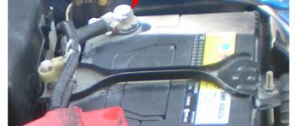
Screw terminal block
The screw connection remains familiar and popular. The mechanism of the product is quite simple and reliable. Screw terminal blocks can be found on household wiring connections, inside many electrical appliances, and even car battery terminal clamps also belong to this group. But, if the electrical terminal blocks for electrical wiring have a copper or brass jumper inside, then the battery terminals are most often made of lead. This is due to the fact that there is acid inside the battery.
The advantage of screw terminal block models for connection is the high-quality contact of the entire area of the cable core with the metal jumper of the clamp. The screw allows you to easily connect and disconnect the wire. On many screw models you can find a screw marked green. It is used to connect the grounding conductor. The special feature of the clamp is its teeth. When pressed hard with a screw, they cut into the metal, improving grip.
The disadvantage of a screw clamp is that it can only be used with copper wire. You can, of course, clamp an aluminum core, but if you don’t calculate the force, the brittle metal will deform. Another disadvantage is the inconvenience of use. In order to connect many wires with screws, it will take more time than to perform a similar operation with spring mechanisms. When in a hurry, inexperienced craftsmen often completely unscrew the clamping screw and lose it. However, these minor problems do not deteriorate the quality of the screw connection, but the fact that the screw connection can become loose during vibration determines its main disadvantage.
Crimp terminal block
This type of electrical product is intended for connecting cable cores with a maximum permissible current of 24 A. The terminal block attached to the cable can withstand up to 5 thousand volts. With one product you can immediately crimp up to 8 prepared terminals for connection. This design greatly simplifies the installation of electrical wiring. According to the type of fixation, the terminal block can automatically fix the contact inside the socket or mechanically, which is done manually. If you correctly calculate the force when crimping the terminal block, you will get reliable contact.
Product labeled PPE
Such terminal blocks are called insulating and look like a plastic cap. The clip is made of heat-resistant polymer that is flame resistant. There is an opinion that PPE is intended to protect the connection from fire. In fact, the terminal block creates a strong mechanical contact and will withstand voltages up to 600 volts.
The principle of operation is simple. There is a usual twist of exposed wire strands. Moreover, all wires must be made of homogeneous metal. To avoid oxidation, it is advisable to treat the twist with paste. There is a cone-shaped spring inside the plastic cap. This will create a strong connection. The cap is put on the twist, twisting clockwise. At this time, the spring presses the veins in turns, creating a strong contact. If two wires of equal thickness are connected, they do not need to be twisted. The bare ends are forcefully inserted into the cap and rotated. The spring inside will do its job itself.
Power terminal blocks on DIN rail
Power terminal blocks are installed on a circuit board or DIN rail. Their complex design allows you to connect wires of different thicknesses up to 300 mm 2. connect aluminum wire with copper, and also simultaneously connect cable cores designed for different power. The power terminal blocks have a tinned copper plate, to which the wire is pressed with a special conical washer, which does not allow the connection to loosen.
Universal and Barrier Clamps
These products have a special design feature - a metal plate. It is divided by cells of insulating material. The cell jumpers prevent the wires being connected from touching. Reliable fastening of the cores is ensured by screws. On metal terminals, aluminum wire practically does not oxidize, which allows the use of such terminal blocks without restrictions. Most often, the connections of wires in the distribution box are made using barrier clamps.
Tags: machine, beat, sconce, view, choice, house, , clamp, grounding, isolate, insulation, pulse, cable, how, design, , installation, power, load, voltage, crimping, lighting, rule, wire, start , , work, size, socket, row, garden, light, twist, connection, ten, type, current, , installation, phase, photo, shield
Features of twisting single-wire wires
Single-core wiring is more difficult to twist than multi-core wiring. There are a number of reasons for this:
- The current-carrying core is made of a rigid metal rod. If the cross-section is large enough, then it will not be possible to bend it with your hands.
- The wire has low ductility. It is susceptible to kinks, so you need to work with it with extreme caution.
- When stripping insulation, the knife blade must be held at an angle of less than 30° to the axis of the wire. Otherwise, the tip will cut into the current-carrying core and damage it.
- Strippings are carried out no shorter than 50 mm. This is the only way to ensure a good connection.
- It is advisable to check the finished twist under load. During operation, it should not heat up more than a solid wire without a connection.
One of the options for connecting wires in a chandelier
If you need to connect a chandelier, then one of the options for connecting the wires coming out of the ceiling with the wires coming from the chandelier would be to use blocks in which the wire connection is secured using screws:
For a chandelier, the option of using wago type terminals, especially if the wires coming from the ceiling are short, will not be very good, since, as already mentioned, in this case the wires cannot be removed (for example, you will need to change the chandelier or wash it) and you will have to cut them off. In the case of terminals with a screw connection, it will be enough to simply unscrew the fastening screws and release the wires.
Connecting broken wires in the wall
Repairs should begin with very careful removal of the plaster in the area of damaged wires. This work is done with a chisel and hammer. As a chisel when laying electrical wiring in the wall, I usually use the rod from a broken screwdriver with a sharpened end of the blade.
Connecting copper wires broken in the wall
Take a piece of copper wire with a cross-section no less than the cross-section of the broken wire. This piece of wire is also covered with a layer of solder. The length of this insert must ensure an overlap of at least 10 mm over the connected ends of the wires.
The insert is soldered to the connecting ends. Solder should not be skimped. Next, the insulating tube is moved so as to completely cover the joint. If a sealed, moisture-resistant connection is required, then before putting on the tube, the soldered joint must be coated with silicone.
Connecting aluminum wires broken in the wall
A prerequisite for obtaining a reliable mechanical connection of aluminum wires is the use of a Grover-type washer. The connection is assembled as follows. A groover is put on the M4 screw, then an ordinary flat washer, rings of connected wires, then a simple washer and a nut.
Step-by-step instructions for connecting broken wires in a wall are outlined in the article “Connecting broken wires in a wall”
Stranded wires, is it possible to connect them?
Most modern apartments are equipped with multi-core electrical wiring. Therefore, sooner or later the question of its restoration or addition arises. What to do in such situations - see our recommendations.
Traditional and fairly familiar connection options can be used for both single-core and stranded wires.
For example, the WAGO spring terminal block is an ideal mounting method. For multi-core current-carrying elements, product grade 222 is used. Stranded copper can be connected by twisting. Here all the conductors are collected into pigtails, and the ends are carefully processed with sandpaper.
Recommendation! Add strength to your wire connection. To do this, provide the conductors with additional insulation. Use modern means, liquid insulation is perfect.
prokommunikacii.ru
Do-it-yourself electrical wiring and creating contacts using terminals
Universal clamp terminals appeared on the market relatively recently, but almost immediately began to be in serious demand not only among specialists, but also among potential clients who prefer to carry out all electrical work at home themselves.
Using self-clamping terminals, you can create strong and reliable contacts between several wires ( three or more ). The main advantage of such terminal blocks is their almost unlimited functionality - they can be used to connect wires whose sizes vary significantly.
The design of the terminals provides for the presence of holes into which pre-stripped conductors are inserted. For example, you can insert a wire with a cross-section of 1.5 mm into one hole, a wire with a diameter of 4 mm into another, a wire with a diameter of 4 mm into the third, and so on. And after connecting them, the contact will be quite strong and reliable.
There are several other ways to connect three or more wires of different diameters, but they are used quite rarely due to the complexity and duration of the process itself. If you want to use one of them, first consult with a specialist who is competent in this area.
Possible problems with such a connection
We list the main problems of connecting two wires to one machine :
1) Overstating the machine - the wiring will burn out
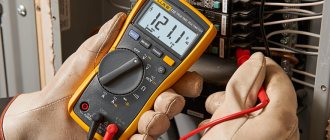
Each machine has its own nominal characteristics. Each wire also has its own characteristics, depending on the cross-section of the wire and its type. In electrical applications, copper wires are the most popular.
In the case when the wire cross-section is designed, for example, for a current of 21 amperes (for a wire with a cross-section of 1.5 mm2), the machine must be installed with a rating of no more than 16 amperes. Considering that with an overload of 45%, any circuit breaker may not turn off for 1 hour (1.45 * 16 = 23.2 A), the wire will have a certain safety margin.
The main purpose of the machine is to protect electrical wiring and electrical appliances connected to it from high currents that occur during a short circuit and overload.
It happens that a circuit breaker is often knocked out, while many simply replace it with a circuit breaker of a higher rating. But at the same time, the installed machine accordingly passes a current whose strength exceeds the maximum possible for normal operation of the wiring. As a result, such wiring burns out, melts, and can even short out due to insulation failure.
When connecting two wires to one machine, follow a very simple rule:
| Both wires must be of the same cross-section and correspond to the rating of the machine! |
For example, a 16 amp machine is available. For proper connection, we take two NYM type cables with a cross section of 3×2.5. The maximum permissible continuous current value for such a cable is 25 A if the cable is hanging in the air, and 38 A if it lies in the ground. Since our cable does not lie in the ground, so as not to test it under maximum loads, a 16 Ampere circuit breaker is the ideal solution for such a cable, and in our case, for two wires.
2) Poor contact at the terminal
When connecting two wires to one machine, a problem arises: how to ensure tight contact between the machine terminal and both ends of the wire.
It has already been written above that the wires must be of the same cross-section. Why? When connecting wires of different cross-sections to the circuit breaker, when you tighten the terminal, one of the wires will not have good, tight contact with the terminal due to the larger wire .
Many “Kulibins” will immediately say “twist two wires of different sections into a twist and you will be happy.” There are statistics for this that show that twisting is the most common cause of malfunction in electrical wiring. Due to poor fastening, the twist will constantly fall out, or, no, touching the terminal of the machine, it will short out.
Two wires of the same cross-section will fit perfectly into the terminal of the machine without twisting. If you need to connect wires of different sections or more than two in number, then it is better to use special cross modules or buses for these purposes.
To connect multi-core wires, there is a decent way out of this situation - NSHVI lugs (insulated pin sleeve lug). These are special connectors that are designed to connect two wires. They have a cone-shaped input and a metal contact that is directly inserted into the terminal of the machine.
NShVI tips are divided into two types: NShVI and NShVI-2. NShVI are designed for terminating the cores of one wire, and NShVI-2 is for terminating two multi-core wires with one sleeve with the possibility of connecting them later to one terminal.
The use of such tips will ensure, firstly, ideal contact of the electrical wiring with the terminal of the machine, and secondly, it will give an aesthetic appearance to your panel. All connections will be neat and reliable without any twists, and two wires will be connected perfectly into one circuit breaker.
Connecting mono-core and multi-core in the terminal of the machine
Friends, especially for comment No. 1 under this article, I decided to consider another way to connect two wires in a machine, and the wires are different in design. We are talking about connecting single-core (monolithic) and stranded wires to the terminal of the circuit breaker.
The NShVI tip will help us with this. We take two wires, remove the insulation from them and crimp them with a double tip. In my example, both monolithic and stranded wires with a cross-section of 2.5 mm2 are crimped NShVI(2)-2.5.
The advantage of this connection is that the wall of the tip itself is thin and under the action of the screw force the sleeve will compress, thereby improving the connection of the wires.
PS There is no need to twist the wires when crimping. Moreover, you don’t need to just stick such a twist under the terminal. When tightening, half of the strands will simply be damaged, and this will lead to poor contact and GOOD heating in the future.
| In general, it is best in such cases to buy another circuit breaker, add it to the panel and connect each cable to its own circuit breaker. It will be BETTER and MORE RELIABLE. But if suddenly..., suddenly... this is not possible, then we use the methods indicated in this article. |
3) The connected load exceeds the power of the machine
It happens that several devices are hung on one machine, the power consumption of which exceeds its rated current, which is why the latter constantly knocks out immediately when the electrical devices are turned on at the same time.
I’ll tell you a situation in which I myself was directly involved. One day I was invited to repair the wiring (at least that’s how they phrased the request over the phone). In the end I came across the following:
- 1. Small gym with two boilers
- 2. 16 amp machine
- 3. Each boiler has a separate cable line with a separate socket
- 4. Both wires are connected to the same terminal of the circuit breaker.
When both boilers were turned on at the same time, the machine immediately went off. Now we look at the power of each boiler. It turned out to be the same: 3.5 kW for each. The cable type for each boiler is a three-core cable VVG-nG-Ls, cross-section - 2.5 mm². Now we count:
- — Current load for one boiler: 3.5 kW × 1000 = 3500/220 volts = 15.9 Amperes.
- — Both machines consume a total of 31.8 Amperes.
As you can see, the load on both boilers exceeded the rating of the 16 Amp circuit breaker twice. In this case, the cable used allows a load of up to 27 A. Accordingly, the wire to the boiler is normal, we leave it. Now we remove the 16 A circuit breaker and install two 20 A circuit breakers.
We connect each boiler to a separate machine. It would be possible to take two 16 A machines, but then the rating of the machine would be one tenth higher than the boiler load (16-15.9=0.1). In this case, constant operation of the thermal protection is POSSIBLE.
Since our cable allows you to connect a 20-amp machine, we can safely connect both machines to 20 A and connect a boiler to each separately. That's it, the problem is solved.
Important! Before installing a machine with a higher rating , be sure to check that the rated current of the cable matches it. If the rating of the machine is much greater than the maximum load on the cable, then the cable may be damaged during the next overload, and the machine will not even react to this overload.
Important! When connecting boilers, it is recommended to immediately install an RCD (residual current device). If you have an RCD, you won't get an electric shock even if you stick your fingers into the socket (but don't experiment under any circumstances!). This device instantly triggers when there is a current leak, so a person does not have time to feel a noticeable electric shock.
TV coaxial cable connection
It is possible to extend or splice a coaxial television cable in three ways: – TV extension, commercially available from 2 to 20 meters – using an adapter TV F socket - F socket; - soldering with a soldering iron.
You can familiarize yourself with step-by-step instructions for connecting a coaxial television cable by visiting a separate article on the site “Connecting a TV cable.”
Connecting tinsel wire by twisting with a single-core or stranded conductor
If it is necessary to give the cord very high flexibility and at the same time greater durability, the wires are made using a special technology. Its essence lies in winding very thin copper ribbons onto a cotton thread. This kind of wire is called tinsel.
The name is borrowed from tailors. Gold tinsel is used to embroider the ceremonial uniforms of high-ranking military officers, coats of arms and much more. Copper tinsel wires are currently used in the production of high-quality products - headphones, landline phones, that is, when the cord is subjected to intense bending during use of the product.
In a cord of tinsel conductors, as a rule, there are several and they are twisted together. It is almost impossible to solder such a conductor. To attach tinsel to the contacts of products, the ends of the conductors are crimped into the terminals with a special tool. To make a reliable and mechanically strong twist connection without tools, you can use the following technology.
The insulation is removed from the 10-15 mm tinsel conductors and the conductors with which it is necessary to connect the tinsel to a length of 20-25 mm with a shift using a knife in the manner described in the site article “Preparing wires for installation.” The tinsel thread is not removed.
Then the wires and the cord are applied to each other, the tinsel is bent along the conductor and the wire core is tightly wound onto the tinsel pressed against the insulation. It is enough to make three to five revolutions. Next, the second conductor is twisted. You will get a fairly strong twist with a shift. Several turns of insulating tape are wound and the twisted connection of the tinsel to a single-core wire is ready. Thanks to shear twisting technology, the connections do not need to be separately insulated. If you have a heat-shrinkable or polyvinyl chloride tube of a suitable diameter, you can put on a piece of it instead of insulating tape.
If you want to get a straight connection, you need to rotate the single-core wire 180° before insulating it. The mechanical strength of the twist will be greater. The connection of two cords with tinsel-type conductors to each other is carried out using the technology described above, only for wrapping, a piece of copper wire with a diameter of about 0.3-0.5 mm is taken and at least 8 turns must be made.
Twist
Just a few years ago there was no alternative to connecting wires by twisting. To make it, you only need to have pliers and a knife with you. Wires are twisted depending on their diameter.
- wrap one conductor around another;
- twist aluminum wire with copper wire.
If you still need to connect a copper wire to an aluminum wire, then the copper wire should be tinned with solder.
Connecting wires in a box using twisting can be done in some variations:
- with different sections;
- from different metals;
- single-core with stranded.
You can twist up to 6 wires in a box. If you plan to connect a stranded conductor, then it must be converted to a single conductor using solder.
There is another option for connecting two wires with a cross-section of more than 1 mm. It involves splicing two pairs of wires. In most cases, this method is used when:
- the conductors are broken;
- it is necessary to increase them when changing the location of the switch or socket.
The splicing process itself consists of the following stages:
- shifting the ends of the conductors in length by 2-3 cm;
- removal of insulation up to 20 wire sections;
- twisting of conductors is accompanied by the creation of two turns on each wire.
When placing the twist under a layer of plaster, it must be soldered. Solder build-ups are removed with sandpaper. Otherwise, they may break the insulation. Due to the fact that the twisted wires have shifted, it makes no sense to insulate them separately. The insulating tape is wound in a triple layer. When laying wires in plaster, you need to use a tube made of vinyl chloride.
The connection of electrical wires with a cross-section of less than 1 mm is carried out by twisting the conductors more than 5 times. The twist is bent in half using tweezers. The use of this method leads to a reduction in the dimensions of the twist and an increase in its mechanical strength.
Despite its popularity, twisted wire connections often do not withstand the maximum loads in the electrical network. As a result, the conductors expand and a gap appears in the twist. The wires oxidize, which leads to loss of contact between the wires.