The reliability of electrical equipment depends on the quality of the connection of wires in the junction box. Switching errors lead to overheating of connection points, short circuits and fire. There are several options for connecting cables to ensure the strength and durability of wiring in residential buildings and technical buildings.
What is a junction box
When installing electrical wiring in premises, it is necessary to install special boxes for switching and routing cables. Housings made of elastic plastic or thin steel sheet are placed in the thickness of the walls.
Boxes can be mounted both in monolithic partitions and in light plasterboard partitions. From the outside, the shield is covered with a plastic cover that does not spoil the appearance of the walls.
Main functions
The box allows you to:
- observe safety precautions;
- distribute wiring indoors;
- Protect connected cables from damage.
Principle of operation
The junction box includes a power wire consisting of 2 or 3 wires (neutral, phase and optionally ground). Lines from sockets, lighting fixtures or switches are laid to the panel. Then the wires are connected in accordance with the purpose of the consumers and the developed circuit. Contacts are protected with tape, tubes or caps. When using terminals, the block body is an insulator; no additional winding is required.
The box maintains the functionality of the electrical system and allows you to disconnect circuits by breaking the contact.
Installation in plasterboard
Marking and cutting holes for sockets
Installing power points in drywall is both hidden and exposed wiring. The wires are invisible to the eye, as in hidden electrical wiring, but they are not located inside the wall and can be reached, as in open installation. The work requires professional tools and steel wire.
How to make several outlets from one:
- Removing the socket and socket box from the wall.
- Thread the steel wire through the hole in the direction of installing the new power point. This is done in order to make sure that a corrugated pipe with a cable can be installed between the profile and the wall.
- Drilling a place for a new socket box.
- You need to twist the rope to the wire and pull it back out.
- Using a rope, a corrugated pipe is pulled between two sockets.
- Wires are pulled into the corrugation.
The final step is to connect the electrical wires.
What to consider when connecting wires
When switching electrical wiring, it is necessary to take into account:
- When carrying out installation work, turn off the power using a switch in the distribution panel. When installing boxes or cables in apartment buildings, you should check the existing circuits for voltage. There have been cases where the wiring of one apartment was partially connected to the cables in the adjacent room; when the power was turned off in the panel, some of the lines remained live.
- The same connection technique must be used within the junction box. When installing terminals of different formats, overheating of the contacts is possible, leading to destruction of the insulation and subsequent short circuit.
- Direct connection of conductors made of copper and aluminum is not allowed. The metals create an electrochemical couple and react to form a film that does not conduct electricity. A decrease in the contact area leads to heating, sparking, and subsequent burnout of the cores.
- The insulation should be cut to a length appropriate to the connection method. For example, for twisting, metal cores up to 60 mm long are required, and when installing WAGO terminals, it is enough to remove the protective layer by 7-10 mm. Damage to the insulation with a knife or a heated soldering iron tip is not allowed; bare wires should not extend beyond the box.
- If the joining was carried out by twisting the cores followed by soldering or welding, then it is necessary to insulate the metal cores and put on a protective cap made of a durable dielectric that does not support combustion.
- When installing wiring, it is necessary to provide a margin of length in the box necessary for connection and subsequent installation. When attempting to join tensioned conductors, the risk of damage to the metal rods increases.
- When using technologies that require the tip of the wire to be designed in the form of a ring, you should close the loop and wind the wire onto the main core of the wire. Otherwise, the joint is easily destroyed and does not provide reliable contact.
Connecting the socket to the electrical network.
All preparatory operations have been completed and our new outlet can be installed and connected.
Remove the top cover by unscrewing the bolts from the front side;
We relax the contacts into which the power wires will be inserted so that the distance between the pressing jaw and the stop is greater than the diameter of the contact wire and it can be freely inserted to a depth of 5-10 mm.
We clean the ends of the power wires brought into the box. We orient the ends of the wires so that they fall into the contact points of the housing and bend them in the form of a springy snake (as in the photo below). This type of bend makes it possible to remove the housing from the wall to tighten the bolts securing the wires to the housing and eliminate sharp bends in the wire when inserting it into the box;
Tighten the bolts securing the wires in the housing sockets.
It is necessary to tighten it very tightly, since when connecting a powerful consumer (for example, a 2 kW heater) and poor contact, the connection point will begin to heat up. This will lead to melting of the wires, plastic housing, and ultimately failure of the entire structure and wiring.
What to do if the ends of the wires leading into the box are short and do not allow connecting an outlet?
In this case, there are several ways out of this situation:
The best, but also the most difficult way is to lengthen the wires by soldering the required length of wire onto them and insulating the soldering area. This method is suitable if you have all the necessary accessories (soldering iron, solder, etc.) for soldering, if the wiring is copper and the length of the supply wire allows this to be done.
If the wire breaks off right under the body of the box, you can carefully open the place where the wiring is sealed in the wall and carry out the extension soldering procedure where it is convenient. Of course, the aesthetic appearance of the wall will be ruined and you will have to plaster this place a little, but still, the loss of appearance will be minimal compared to replacing the entire wire from the junction box to the outlet.
If the electrical wiring is aluminum, and it most often breaks, the soldering method will be unacceptable.
In this case, if the length of the broken end allows, you can use a terminal. On one side we insert the stripped broken end of the wire into it, on the other, a stripped piece of extension wire and tightly tighten the contact points.
Of course, this method creates an additional contact point where heating is possible, which creates a certain risk. Otherwise, you will have to replace the entire supply wire from the junction box to the wiring outlet from the wall.
It is strictly not recommended to make connections on terminals and twists in the wall, with further puttying and walling up of wires.
This was a small digression, but let's move on to further installation. We have connected the wires and now we need to install the socket in its place in the box.
Methods for connecting wires in a junction box
To connect the cores, the following methods are used:
- permanent connection by twisting the cores (with or without applying a layer of solder) or installing metal tubes with subsequent crimping;
- detachable mating using PPE caps, screw blocks or bolts, as well as terminals manufactured by WAGO.
Twisting method
One of the common methods of connecting electrical wires to each other is twisting the wires, but this method is contrary to the rules of the Electrical Installation Code. The wound cores do not provide reliable contact; when a powerful load is connected, the joint overheats. It is recommended to use twisting as a temporary option for connecting wiring.
Correct connection of sockets with a cable
All sockets located on the same electrical group have the same connection diagram - parallel. But you can “parallel” sockets in different ways: connect them in junction boxes (twisting, terminals, soldering) - 1. or connect them to each other at the terminals, bypassing these boxes (connection with a cable) - 2.
Which socket connection to choose. By connecting sockets with a cable, you can significantly save on material - wires, boxes and, accordingly, significantly reduce labor costs. However, currently in the Electrical Installation Rules (PUE) there is a clear and unambiguous prohibition on breaking the PE conductor (“ground”).
If you are changing the electrical wiring in your apartment (house), there is nothing particularly to be afraid of - after all, you do not need to officially put the facility into operation, but you must agree, it is better to sleep peacefully, knowing that the electrical wiring of your home is in order and meets all regulatory electrical safety requirements.
How to properly connect sockets with a cable. without violating the PUE? There is an alternative: the figure shows a method for connecting sockets in this way. The method is quite old, but proven, and for reliability it is better not to limit yourself to the “ground” wire, but to leave the current-carrying wires – phase and neutral – unbroken.
With this connection of sockets, the load on the terminals of the first socket where the power “comes” will be limited only by the power of the household electrical appliances included in it. This method of connecting sockets extends their service life and, most importantly, keeps the PE conductor (“ground”) intact.
Copyright 2010-2016 When using site materials, an active link to remont220.ru is required
The site uses cookies. By continuing to browse the site, you agree to the use of cookies.
Advanced tasks
In addition to connecting single cables, when laying electrical wiring you need:
- combine several cores made of homogeneous material into a single circuit for subsequent connection to a power circuit or ground loop;
- connect cables with cores having different cross-sections or designs.
When installing new electrical wiring in houses built before the early 2000s, it is necessary to connect copper conductors to aluminum ones. The most reliable way is to lay copper cables with the removal of aluminum cables, which are not designed for high loads and are prone to loss of strength. If you do not plan to remove the old wiring, then for switching use blocks with screws or special tubes designed for pairing dissimilar metals.
Connecting a large number of wires
To connect several wires in a box use:
- WAGO pads that provide strong contact and take up little space;
- connectors with screw contacts and the possibility of mounting on a rail in the distribution panel;
- metal sleeves, crimping requires pliers, the connection requires subsequent insulation;
- twisting into a bundle followed by soldering or welding;
- connection using a PPE cap, the technique is suitable for a limited number of cores;
- twisting the cores followed by wrapping the bundle with insulating tape or installing a shrink tube.
Cores with different sections
When installing electrical wiring in an apartment or residential building, wires with different core diameters are used (depending on the load power). For high-quality connections in junction boxes, it is better to use WAGO clamps. The manufacturer offers products designed for installation of cores made of different metals. A special coating on the contacts prevents electrochemical corrosion and destruction of the material.
Another connection method is to twist cores made of the same metal into a bundle, followed by welding or soldering.
Stranded and single-core conductors
When connecting multi-core cables, it is necessary to remove the insulator and weave the wires into a single braid. Then you should treat the surface with flux and apply solder (the technique is suitable for aluminum products). If connection is supposed to be made with WAGO terminals, then tinning of the cores is not required. To connect wires with different core diameters, it is best to use WAGO clamps with individual contacts. The difference in core sections does not affect the fixation density and contact patch, ensuring reliable operation of electrical wiring under load.
Is it possible to connect an outlet to the switch?
Imagine the situation: you have renovated your premises, all the electrical wiring is walled up in the walls, and there are no backup boxes or socket boxes. An outlet needs to be installed in one of the rooms. Placing it next to the distribution box is irrational, the location is too high. But I don’t want to lay open wiring (especially, ditch the wall).
There is a switch in a convenient location that clearly has voltage. How to make a socket from a switch if it is possible to aesthetically place them next to each other?
To answer this question, let’s remember: what types of lighting schemes with switches are there?
Classic connection: tap from the distribution box.
The neutral conductor is inserted into the lamp from the box. In the box itself, a break in the phase cable is organized (it is opened using a switch), then the phase enters the lamp along the same path as the zero.
With this scheme, only the phase conductor is present in the body (installation box) of the switch. It will not be possible to organize a closed electrical circuit to connect an additional electrical appliance (via an outlet). You can use the phase from the switch, but you still have to lead the zero from the distribution box, which makes the idea pointless.
Conclusion: With this type of lighting arrangement, it is impossible to connect the socket to the switch.
The switch is located between the power source and the lighting fixture.
This scheme is less common, but in some rooms it is used. If at the design stage it was decided not to use distribution boxes in the lighting network, you are in luck. The switch wiring box contains both neutral and phase wires.
The sequence of work is as follows:
- We dismantle the existing switch without touching the installation box.
- We determine the routes for laying the input and output cables. If you have a diagram and plan for the electrical supply of the room, this is not difficult to do.
- Carefully drill a hole for the socket box.
- We install terminal blocks in the switch box and connect the socket according to the following diagram:
Safety regulations:
Since the current wiring is intended for lighting, most likely the cable cross-section is no more than 1.5 mm². The maximum possible load for such a cable (provided that it is copper): 3.3 kW. That is, not very powerful electrical appliances can be plugged into this outlet. The maximum is a vacuum cleaner. Well, phone chargers, a power supply for a router or an antenna amplifier - no problem.
Safety precautions when working in land and water
Tips for complying with safety requirements when installing wiring outside the home:
- To ensure insulation of wiring located in damp soil or under water, shrink tubes with an applied adhesive backing are used. When heated, the mastic melts and fills the cracks; to increase the tightness, it is recommended to install several tubes with overlapping edges. To ensure maximum protection, solid insulated cable should be used with connections to dry points.
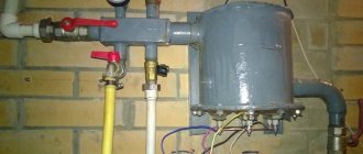
- When installing the wire in the ground and using a junction box with sealed inputs, you should connect the wires with blocks, and then fill the cavity with silicone sealant. After polymerization of the composition, install the cover and pass the cable and box through the plastic pipe. The outer shell will protect the insulation from damage by rodents and increase the resistance of electrical wiring to seasonal soil heaving.
- To connect wiring located under water, you can use couplings filled with compound. After joining the cores and installing the sealing rings, a polyurethane-based composition is poured into the cavity, which, when hardened, protects the wiring from moisture and mechanical damage. An alternative technique involves using LETSAR tape, which hardens and seals the joint.
Installation
The junction box is installed on the wall with a lowering of 10–30 cm from the ceiling. Moreover, this is done in such a way that there is open access to its lid. Checking the condition of the wires should be carried out on a regular basis.
Step-by-step instruction
Installation of the junction box is carried out in four simple steps:
- Fastening the box to the wall according to the wiring diagram.
- Planting wires inside and then connecting them to each other.
- Checking the assembled electrical network.
- Closing the electrical installation product with a cover.
The junction box is secured using self-tapping screws or plaster (if it is recessed into the wall).
Arrangement of input cables in the box
Wire connection methods
According to the PUE, the electrical wires inside can be connected:
How to properly connect wires in a junction box
Twist
Twisting is the fastest and at the same time the most unreliable way to connect indoor electrical wiring. To cover the exposed wires, special plastic caps or electrical tape are used.
Twist connection method
Soldering
Soldering is done with tin on top of the pre-twisted wire. This connection is much more reliable and durable. However, such installation takes a lot of time.
Welding wires
For welding you need an inverter welding machine. This method is even more reliable and more complex, but as a result, the two connected cores actually turn into a single solid one. It is recommended to choose it only in special cases. For example, when grounding is done in a private house under a powerful load or additional pumps and uninterruptible power supplies are connected for a gas boiler.
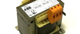
Terminal connection
If the wires are made of different materials, then it is best to use terminals with screw or spring clamps. The terminal connection is extremely simple to make; you only need a screwdriver. The most important thing here is not to overtighten the clamp bolts.
Terminal connection of wires
Crimping
When crimping, press pliers and sleeves are used, made of the same metal as the cores, and sized to match the thickness of the wires being connected. Some craftsmen use pliers for this, but such connections are rarely reliable. It's better not to experiment.
Crimping connection method
Wiring diagrams
To avoid any confusion when connecting electrical wires, it is worth preparing in advance the wiring diagrams for all installed junction boxes. This drawing should indicate “from where and where” each core goes. In general, it is advisable to use different colored wires to avoid confusion.
Wiring diagram
Basic wiring diagrams
There are several schemes for connecting wires in a junction box:
- for switching sockets;
- for organizing switches with one or more keys.
The box can simultaneously contain contact pairs for different consumers. When developing electrical wiring drawings, you should take into account the number of wires, the switching method and the dimensions of the connectors. In some situations, it is advisable to install several boxes, ensuring ease of connection and the availability of free space for air circulation to cool the contacts.
Connecting sockets
Proper connection of wiring in a distribution box involves organizing a separate line for each outlet, consisting of 3 wires (zero, phase and ground). When switching, the color marking of the insulation should be taken into account. For example, according to the PUE, cables with a brown sheath are used for the phase, with a blue sheath for the neutral line, and with a yellow insulator with a green stripe for grounding.
Connecting a switch with one key
To make switching in the junction box of a standard switch, it is necessary to insert a power wire and make a branch to supply the phase to the contact group. The neutral cable goes straight to the lampshade. The switch breaks the phase and ensures safe maintenance of the lighting device. Using a similar technique, you can turn off a switch installed on the surface of a wall or buried in the partition material. If the key has a control LED, then the element is included in the line by default and will start working when power is applied.
Two-gang switch
Correct connection of a switch with 2 keys requires wiring of the common phase, which goes to the contact plate. 2 wires are laid from the device to lamps or a chandelier with double switching of lamps. The zero is supplied directly to the cartridges and is not interrupted by the switch contacts. Using similar technology, you can connect devices with 3 keys or connect several switches to control a multi-tier lighting system in a room.
Junction box installation technique
If you take into account all the rules and nuances, it turns out that distributors are considered the easiest device to install, despite its importance in the integrity of the power system. For decent and high-quality installation, you will have to use several techniques, on the basis of which the work algorithm is based.
- The initial difficulty lies in finding a place where our distribution box will be located. If you are installing distribution boxes for exposed wiring, you cannot limit its accessibility for repairs. It is very important that replacement or reconstruction of cable installations is not costly.
- In some individual cases (usually in apartment buildings), several distributors are installed in order to reduce the load on the network. However, this is not a mandatory condition. If this is your first time encountering such installation, it is important to remember about the feed-through and end boxes. In such cases, the entrance structure remains the walk-through structure.
- We secure the boxes, for this we use special clamps. When fixing the device to a wall or ceiling, it is important to ensure that the place is perfectly level.
- Let's start connecting the wires. First you need to figure out how consumers should be connected; to do this, think over an exact diagram, which will later become your assistant, or refer to this article.
Wire distributor with terminal block
Attention! The introductory connection is made at the end of all installation work and is connected to the meter.
Try not to use the twisting method when connecting conductors, since under current conditions this is unsafe for humans. If your box is not equipped with terminals, it is better to buy them yourself.
Checking the correct connection of conductors in junction boxes
After completing the installation work, the machines in the panel are turned on. If the fuse trips, check that the cables are connected correctly. Otherwise, the maximum load is connected to the line for 2-3 hours. The test allows you to determine poor-quality connections; when operating the test equipment, an increase in the temperature of the joints or the appearance of the smell of overheated wiring is not allowed. After completing the test, interrupt the current supply to the room, check the integrity of the insulation and close the boxes with standard lids.
How to disconnect the box
In any room there is at least one branch box, called a junction box. Sometimes an additional one can be mounted on sockets - provided that they are significantly removed from each other. Disconnecting the box is necessary for many preventive and repair work.
All wiring in residential and domestic buildings is laid in the floor or along the walls. Cables and wires in a garage, country house, apartment have an exit from the electrical panel, where a meter is located that takes into account electricity consumption, safety plugs or circuit breakers, and come to the location of the branching and junction boxes. Here, the conductors are twisted and connected using special clamps.
Plastic PPE caps
The abbreviation SIZ stands for connecting insulating clamp. It is a cone-shaped cap made of plastic, which contains a steel spring with an anodized coating.
The technology for using the product is as follows:
- Remove the insulation from the wires to be connected to a distance of 2-3 cm.
- Gather the wires into one bundle and insert them into the cap until it stops.
- Applying force from the blind part, turn the cap by hand 2-3 turns. A traditional twist is formed inside, secured with a spring.
Such clamps are quick-release and reusable, provided that the spring was not damaged during dismantling. With their help, the connection in the box is made quite quickly, does not require insulation and does not take up much space.
Details on how to connect wires in a junction box in various ways, including using caps, are described in the video:
Application of connecting terminal blocks
Terminals for quick connection of wires are of 2 types:
- screw clamps in the form of blocks;
- Wago type self-clamping connectors
The technology for splicing electrical cables using terminal devices is quite simple. The wires need to be exposed only 1 cm and inserted into the clamps. In the first case, the cores are fixed with screws, in the second - with levers or automatic latches. By the way, terminals with latches are disposable, while terminals with levers are used repeatedly.
We list the advantages of screw terminal blocks:
- Fast and reliable docking.
- Ability to connect copper wiring to aluminum.
- Provides a detachable connection.
- Does not require additional insulation.
One of the disadvantages of the pads is their size. It happens that when there is a large accumulation of wires coming from several switches or sockets, the screw connector does not fit inside the junction box. Point two: single-core wires are fixed without problems, but multi-core wires are flattened with screws, which is not good. Therefore, it is better to pre-tin such ends.
Wago clamps, which allow you to connect up to 4 wires of the same cross-section, have the same advantages as screw terminals, but take up less space. In this case, the operation of disconnecting the entire junction box will take about 5 minutes, which is very convenient for installing electrical wiring. Judge for yourself: the bare end needs to be inserted into the clamp with pliers until it stops and that’s all.
Since there are cheap products on the market from various Chinese manufacturers, self-clamping terminal blocks have acquired a dubious reputation. The fact is that in low-quality connectors, the contact weakens over time, causing them to overheat and melt. If you purchased original Wago products, then there will be no problems; in other cases, it is better not to take risks and connect only lighting wires with clamps (power supply to switches, chandeliers, and so on). Wire the sockets using a different method.
The master will tell you how to use self-clamping terminals correctly in his video:
Soldering and welding
When wiring in residential premises, the Electrical Installation Rules regulate the use of wires with copper conductors. The electrical characteristics of such wires are much better than those of wires with aluminum conductors. Although the latter are much cheaper, if you want everything done correctly and the wiring is safe and reliable, use only copper wires.
Let's look at how soldering is done correctly. To implement this, you will need a household soldering iron with a power of at least 40 W, a piece of rosin as a flux (sometimes an alcohol solution is used) and solder. The solder can be ordinary tin or special lead-tin solders of the POS-61 brand or similar solders. They are produced in the form of wire, rod, strips.
The cable cores that need to be connected are stripped of insulation to the required length, sufficient for reliable contact. They are then treated with flux. To do this, the core is placed on a piece of rosin (treated with a brush using liquid flux) and heated with a soldering iron tip. This process removes the oxide film from the metal surface. After this, a solder tip is used to apply a layer of solder to the cable core and tinning it is carried out. This procedure must be carried out with all the cores that are to be connected.
At the final stage, the tinned ends of the wires come into contact, and a drop of solder is applied to them from the soldering iron tip, which ensures reliable contact. Another way to use a soldering iron is to pre-twist the wires, and then treat them with flux, tinning and soldering.
If you have a special welding machine with a carbon electrode, then instead of soldering, you can weld the connected wires. But such equipment belongs to the professional class and requires certain skills. After all work has been completed, the resulting connections are insulated using electrical tape.
Terminal box arrangement
It all depends on your skills, capabilities and the required reliability and durability of the connection. Almost all of them, except the last two, when properly performed, meet these requirements. The most reliable connection, of course, is welding. Then comes soldering, crimping, screw tightening, twisting and, finally, clamping and self-clamping terminals.
Junction box selection criteria
When choosing a junction box, you should consider the following criteria:
Distribution boxes come in large and small, round and square, plastic and metal, with and without terminals. Which one to choose is up to you, based on your specific conditions, skills and capabilities.
Purpose of the telephone box
A telephone junction box is a protected metal or plastic device that is designed to connect subscriber lines to the main distribution network. In addition, the telephone box protects the connection elements from external influences. This device can be installed on different planes: niche, wall, etc. It can also be installed outdoors and inside a building.
There are 2 types of telephone boxes:
- Modernized
- Plastic
The upgraded device is used to establish the connection of communication lines indoors, and the plastic ones are used in places with high voltage. Plastic bushings and clamps provide a secure connection inside the box. And some models have a device for protection against thunderstorms. The main component of the cable device is plinths, which are secured inside the box using special installation clamps. The box is quite spacious (150 pairs) and is protected by locks and other devices.