For installation in difficult conditions and to protect the electrical line from damage, armored cables are used, representatives of which are VBBbShv and AVBbShv. Armored is an electrical cable protected by a layer of metal tapes or layers of metal wire. Definitions of names and types of cable products and related terms are described in GOST 15845-80. A prerequisite for its use is the grounding of the armor, since current standards and requirements indicate the need to ground all conductive parts of the electrical installation. In this article we will look at how to ground an armored cable.
Grounding armored cables indoors
Armored cable 0.4 kV can be laid over any metal structures if they are grounded and also accessible for maintenance.
Laying on wet concrete and wooden surfaces is prohibited. In this case, you need to provide a gap of at least 5 cm between the line and the surface; for this you can use various brackets or lay the line in metal pipes and gutters. An armored cable can be inserted into a building through the foundation and walls. In order to eliminate the possibility of damage, a metal or plastic pipe with a diameter 2 times larger than its outer diameter must be laid at the cable entry, or at the point of transition through a wall or foundation.
The next step is that the armor needs to be grounded in the shield and at the side of the support from which it comes. Also, as described above, there should be no connections in this area (support-shield). At the input to the shield, the cable is divided into cores, which are connected to switching devices (switch or automatic circuit breakers), and its armor is connected to the shield body. That, in turn, must be grounded.
In cable structures (trays, galleries, overpasses, under floors), it is permissible to ground the armor by ensuring contact with metal boxes, channels or other grounded structures.
To organize an electrical network in a private house, it is connected to the power line using an overhead or underground connection. In the case of laying cables underground, VbBShv is often used; its armor, as in the cases described above, must be grounded on both sides.
The screen of control cables or optical cables must be grounded on at least one side. This is done to reduce or completely eliminate the influence of electromagnetic fields on the information line.
However, this task is better handled by double-sided grounding. The screen is connected to the main shield using a flexible conductor with a cross-section of at least 4 square meters. mm.
How to properly ground armor
The armored cable is grounded using a flexible, uninsulated wire. At the same time, along the entire length of the line, the armor should not have breaks, that is, it should be solid. If there is a need to break the cable, for example, to repair it or to connect several sections, then the connection of the armor and the shell of the coupling is made with flexible stranded copper conductors. To select the wire cross-section for grounding, use the table:
| Cable core cross-section, mm | Grounding conductor cross-section, mm |
| to 10 | 6 |
| 16, 25,35 | 10 |
| 50, 70, 95, 120 | 16 |
| 150, 185, 240 | 25 |
Rules for grounding pipelines
Grounding of pipelines is a mandatory measure, enshrined in the PUE. This is how you can increase the safety of their operation, because static electricity accumulates in pipe systems, plus there is always the possibility of lightning striking the pipes. The requirements of the rules for the construction of electrical installations are to provide grounding not only for external pipelines, but also for internal ones (technological and communication).
The PUE clearly regulates how pipelines should be grounded.
- Firstly, the pipe system must be a single continuous network connected into a single circuit.
- Secondly, pipelines must be connected to the grounding system at at least two points.
As for the first position, this does not mean that the pipeline system itself must be continuous. Here it will be enough to ensure the connection of sections or individual pipelines into one single network, for which so-called wafer jumpers are most often used. In fact, this is an ordinary copper wire of the brand either PVZ or PuGV. Fastening of jumpers to the pipeline is ensured by welding, bolting, or a grounding clamp for pipes is installed.
As for the second position, experts recommend not to scatter along the entire line of the technological chain, just to make a connection at the beginning and end of the circuit.
Comments:
Step
An intelligent article, described in some detail, thanks to the author. But fastening it with tapes to the support every 50 cm is overkill. It is not necessary. According to the PUE, this distance is 100 cm and is sufficient to firmly hold the cable.
Larion
So I counted the current collectors. Can you tell me how much cable power reserve should be taken in order for the whole system to work?
Magomed
Larion, ideally, the more, the better. The more powerful the cable is installed in your home, the less likely it is that it will ever fail. More power means longer service life.
Leave a comment Cancel reply
Related Posts
Features and scope of use of multi-core flexible copper cable Armored copper cable for your home and site Correct replacement of wiring in an apartment of a panel house - what you need to know and be able to replace electrical wiring in an apartment, list of necessary tools and materials
Marking of cables with a layer of armor
Protected products often have fairly long markings. To learn how to recognize brands of armored cables, you need to figure out what the letters in the markings mean, for this we will look at the example of several brands.
For armored cable AVBbShv the marking means:
- A - aluminum conductors;
- B - vinyl internal insulation;
- B - armored;
- b - without a pillow;
- Shv - outer sheath in the form of a pressed PVC hose.
VBBShvng, similar to it, stands for this:
- there is no letter “A” at the beginning, which means the wires are made of copper;
- B - vinyl internal insulation;
- B - armored;
- b - without a pillow;
- Shv - outer sheath in the form of a pressed PVC hose.
- ng - does not spread fire.
The third brand TPPepB is an armored telephone, which stands for:
- T - speaks about the purpose - “Telephone”;
- P - polyethylene insulation;
- P - polyethylene insulation;
- ep - screen made of aluminum polymer tape;
- B - armor made of two table bands.
Main types and types
Before moving on to the main topic of our article, let's figure out what kind of cables there are.
Control cables usually consist of a set of cores from a couple to several dozen. Used for assembling control circuits and connecting groups of sensors and actuators. Can be shielded - this will help avoid interference and give additional strength to the product. An example of such a cable is KVVG - copper with PVC insulation. At the beginning of the marking of such cables there is usually the letter K.
KVVG
Information and signal cables. These include twisted pair and fiber optic. Optical fiber can be single-mode or multimode, depending on its purpose and design. Telephone “noodles” also belong to this class. Twisted pair cables can be supplemented with screens and protective sheaths, like other types of cable products.
Armored twisted pair cable for external installation, self-supporting
Power cables are used to connect electrical equipment to the power supply. If the first letter in the marking is A - for example, AVVG, then the cores in it are made of aluminum. If there is no letter A, for example VVG, then it is copper. The remaining letters tell us about the insulation materials and the presence of additional components. VVG stands for Vinyl-Vinyl-Bare, that is, two layers of PVC insulation and a bare core.
VVG 4×1.5
Power armored is a separate type of product designed for operation in difficult conditions in aggressive cutting or under possible mechanical stress, including in the ground. Information cables can also be protected by armor. They can be either aluminum or copper. An example is an armored copper cable VBBShV with insulation made of cross-linked polyethylene and a sheath made of pressed PVC hose, and armor made of steel tapes, you will learn more about this below.
VBBSHV with five cores
A special word needs to be said about the load-carrying geophysical cable - this is a type of armored product used for research purposes in the oil and gas industry, in marine and geological expeditions. It has another name - logging.
Logging cable
Recommendations
The grounding conductor is connected to the armor using soldering, and if the coupling is sealed, then with bolts or a clamp (clamp).
To ensure high-quality solder contact, the soldering points are first cleaned and tinned with solder, for example POSSu 30-0.5.
Next, using a wire bandage, fix the grounding conductor on the tinned area and solder it. Solder fat is used as a flux.
For solderless connections, clamps or constant pressure springs are used, which ensure reliable electrical contact around the protective layer.
For tape armor, the grounding is connected to the strips, and for wire armor, the grounding is connected around the circumference to all the wires. When connecting the ends of building lengths, sealed couplings are used; their kit includes:
- waterproofing elements;
- connecting elements (for example, tips with shear bolts);
- grounding wire, it connects the armor of both connected ends;
- clamps for connecting wires to tapes or wire armor.
To properly cut the cable, the top layer of insulation is removed to a greater length than the bottom layers. In this way, the conductors are separated and a section is formed on the surface of the armor for the ground connection. Depending on the coupling, the manufacturer may provide a template for correct cutting.
Sources
- https://www.elec.ru/articles/kak-chitat-markirovku-kabelya/
- https://shallot.ru/how-to-properly-ground-the-armored-cable-cable-shield-grounding-is-it-necessary-to-conduct-it.html
- https://altyn-stroy.ru/zazemlenie-broni-kabelya-pue/
- https://elektrik-sam.ru/jelektroprovodka/3460-kak-sdelat-zazemlenie-broni-kabelja.html
- https://alekstroy.com/zazemlenie-bronirovannogo-kabelya-pue/
- https://samelectrik.ru/kak-sdelat-zazemlenie-broni-kabelya.html
Tightness of the outer shell
The outer shell of telephone and trunk communication cables is checked for leaks before laying the wires in cable channels, trenches and other highways, as well as after completing the installation of cable couplings. The test is carried out by applying high pressure to the cable and observing the readings of pressure gauges installed at control points
In communication cables with metal insulation, pressure gauges are connected through special valves soldered at the measurement locations. If the sheath of communication cables is polyethylene, then pressure gauges are connected through special bushings with valves. When using wires in which the voids are filled with hydrophobic materials, the integrity of the insulation is measured using special instruments. These devices determine the quality of the shell by measuring its resistance to ground.
For mobile equipment
There are other systems for organizing protective grounding of equipment (TT and IT, for example), which use a neutral conductor as a “zero” conductor and involve the arrangement of a re-charger on the consumer side.
In the first case, the neutral at the substation is solidly grounded, and in the second, it is not connected anywhere at all. These options for switching on the neutral are rarely used and only in cases where it is necessary to re-ground mobile electrical installations (provided that this is very difficult to do on the generator side).
According to GOST 16556-81, the IT system discussed above is used for mobile electrical equipment, during the implementation of which re-grounding is organized on the consumer side. This standard specifies the technical characteristics and parameters of the storage facility, which is temporarily installed in the area of upcoming work.
Integrity of current-carrying conductors and presence of short circuits
The integrity of the cores is checked before the start of installation work and after its completion. To carry out measurements, it is necessary to free a small section of the wire from the insulation, while violating the integrity of the threads or tapes with which the cores are fastened together is not allowed. To determine the presence of a line break, a signal generator is connected to one end, and the wires on the other side are short-circuited with each other. The location of the break is determined using a microtelephone handset.
One wire of the tube is connected to the shielding shell, and the second to the core being measured. If there is a short circuit in the speaker of the handset, characteristic clicks are heard. Damaged conductors are marked and the measurement results are recorded in a log.
Measuring the insulation resistance of protective hoses in which communication cables are laid is carried out using megohm meters or other special instruments.
Installing cables in the ground - 20 common mistakes. The formula for the ideal underground entrance to the house.
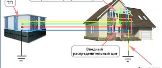
When installing an electrical input into a house, each of us thinks about how it is better to do it - overhead or underground? Installation of air SIP is always much faster and several times cheaper. Firstly, it is more reliable. And secondly, it does not spoil the facade of the building or the appearance of the surrounding area.
Often these two methods are combined. Initially, an input is made to a special pipe stand from a support.
And from this distribution cabinet the cable is laid in the ground and brought into the house. When the support is located not far from the building, some SIP wires are mounted directly on the facade.
But we will turn specifically to the underground input. Let's look at what difficulties you will encounter when laying cables in the ground and place special emphasis on common mistakes when performing this work, which ultimately, sooner or later, lead to failure of the cable line.
Cable installation in the ground can be done in two ways:
without any protection (using armored KL grades)
in pipes or special corrugation
Let's look at the first method first. Here, as a rule, a cable with tape armor is used - VBBbShv or AVBbShv.
It is not at all necessary to use armor of the type AABL, AAShV, where there is a one-piece cast protective shell made of aluminum. It could just be ribbons overlapping each other.
In this case, armor protects not so much from external influences (someone started digging where they shouldn’t), but from deformation and traction forces during soil heaving.
The same applies to the SIP wire. It cannot be laid in the ground, even in pipes.
You can often find videos on YouTube where copper CLs with 6mm2 conductors or 10mm2 aluminum are used. This is explained by the supposedly small number of electrical appliances in the house or country house.
In terms of load, this may be enough for you, but in terms of compliance with the requirements for the minimum cross-section of the PEN conductor, you will have a violation. For single-phase power supply, the cable must be three-wire, for three-phase power supply, it must be five-wire.
The selected cable should be carefully laid in the trench. What size should it be, what distances should be maintained when excavating it?
It is necessary to maintain a certain distance of 60cm.
After laying in the ground, the cable should not fall on the line of action of the foundation force, directed at 45 degrees from the base.
Standardized clearances from plants and trees on your site are also required. Here are the minimum dimensions for underground cable laying from nearby utilities, structures and obstacles.
What dimensions should this trench have? You can navigate here by the standard project A5-92 “Laying cables with voltage up to 35 kV in trenches” - download.
The cable depth is 0.7 m. Please note that this is the distance from the surface to the top of the cable itself.
Where did all these numbers even come from? Why can’t you just bury the cable in your yard to the depth of a spade bayonet? Why such torment?
You are not doing the installation in a public place on a city street or at a construction site where heavy vehicles will drive.
By laying it as close to the surface of the earth as possible, you will lose the main advantage of underground installation - the lack of influence of ambient temperature and weather conditions.
The upper layers of the soil warm up much more, and moisture after good rains simply will not reach the cable sheath if it lies at 70 cm. The same cannot be said about 30-40cm.
The minimum trench width is calculated by the formula = cable diameter + 100mm on each side for a sand bed.
By the way, so that such labor-intensive work on digging a trench does not go to waste, some additionally lay a grounding loop in it. Just don’t forget about the minimum margins of 300-350mm.
Well, in the case of protecting the cable with a pipe, the circuit is not a hindrance at all. After all, it is not necessary that it be in the shape of a triangle or square.
And if the geometry of the site and the location of the input allow, the same trench is adapted for simultaneous installation:
Shielded control cable
The world of modern communications requires the installation of many wiring systems. Therefore, nearby (in the same channel, gutter or well) there are cables for various purposes. The electromagnetic fields existing in each conductor influence each other. To neutralize the resulting interference, a shielded cable is used.
The screen is needed to protect the internal electromagnetic field from external influences and to minimize the internal influence on currents and fields of other conductors. The appearance of electromagnetic potentials on the surface of the cable product is removed by grounding the screen.
Among the many shielded products, control cables have a special purpose. They serve for the exchange and transmission of data in conditions of limited access. The control cable provides reliable communication with devices to receive the necessary signals and messages. The product is sometimes referred to as "multi-core control cable".
The shield in control cables is designed to protect information, the transmission of which is complicated by the influence of electromagnetic fields from external sources. The screen is made from thin foil or copper wire. The shielding coating is also made of tinned wire braid. There are combinations of an electrostatic screen made of tinned drainage wire with a metallized film.
Design features of control cables, types of screens
The basis of the structure is current-carrying conductors. They are made mainly from copper. Insulation of conductive rods is carried out using PVC materials.
The cores are twisted in pairs using the optimal pitch. Pairs can also be twisted along their length while maintaining the optimal pitch. Thanks to pair twisting, crosstalk is effectively suppressed.
The structure of the control cable contains a filler, a screen, and an outer sheath. To fill the gaps between the cores, special materials are used to give the cable a rounded shape. Some control cables are armored.
The control cable shield ground is located directly under the outer sheath. Its usual place is the top layer of the layer. The screen has the form of a winding consisting of copper (aluminum) tape or foil. The continuity of the screen is ensured by the overlap of the protective layers. It is only required to maintain the permissible bending radii.
It is allowed to produce screens whose design is distinguished by longitudinally applied corrugated aluminum tapes with overlap. Some types of shielding are made using aluminum foil, along which copper wire is located longitudinally.
The outer shell is made of various PVC materials. Many of them are flame retardant and self-extinguishing. The outer sheath makes the control cables resistant to chemicals and oils.
Application areas for shielded control cables
Screened control cables are divided into 2 main types according to their intended purpose:
- for fixed installation, grades KVVGE and AKVVGE are used;
- For non-stationary laying, the KGVEV brand is used.
The letter "E" becomes common when labeling varieties. It indicates the presence of a screen. Screened control cables are used for the purpose of connection between electrical devices and electrical distribution devices. The possibility of laying in groups is provided.
The range of applications is significantly expanded when flexible control cables are used. They are used in conducting and organizing:
- electrical installation work;
- automated control systems (in production facilities of various levels of complexity);
- air conditioning and heating technology;
- transportation and automation systems;
- power plant equipment;
- security systems;
- alternative energy;
- control of machines and devices.
Flexible control cables are effectively used in moving circuits. Certain types of control cables can be used outdoors because the conductors are resistant to ultraviolet radiation.
The range of control cables includes products designed for intrinsically safe installations. Some varieties are resistant to abrasion, mechanical stress, and aggressive chemicals.
Types of material (profiles)
According to the requirements of the PUE, which contain instructions on what the resistance of current flow in the ground should be, in most cases this indicator is set at a level of no more than 4 ohms. To obtain this value, you usually have to make a lot of effort to adhere to the same technology requirements.
First of all, this concerns the materials used in assembling the grounding loop, selected based on the following conditions:
- When choosing pins, preference should be given to ferrous metal blanks;
- The most commonly used rod is a standard size of 16-20 mm or a corner with parameters 50x50x5 mm and a metal thickness of about 5 mm;
- It is not allowed to use reinforcement as circuit elements, since it has a hardened surface that affects the normal flow of current;
- For these purposes, it is pure rod that is suitable, and not its reinforcement substitute.
Note! For areas with dry summers, thick-walled metal pipes are best suited, the lower end of which is flattened into a cone, and then several holes are drilled in this part of the pipe. According to the provisions of the PUE, before placing them in the ground, holes of the required length are first drilled, since driving them manually is quite problematic
In the case of a particularly dry summer and a sharp deterioration in the parameters of the ground electrode, a concentrated saline solution is poured into the hollow parts of the pipes, which makes it possible to obtain the resistance that should be in accordance with the requirements of the PUE. The length of pipe blanks is selected within 2.5-3 meters, which is quite enough for most Russian regions
According to the provisions of the PUE, before placing them in the ground, holes of the required length are first drilled, since driving them in manually is quite problematic. In the case of a particularly dry summer and a sharp deterioration in the parameters of the ground electrode, a concentrated saline solution is poured into the hollow parts of the pipes, which makes it possible to obtain the resistance that should be in accordance with the requirements of the PUE. The length of pipe blanks is selected within 2.5-3 meters, which is quite enough for most Russian regions.
This type of profile blanks has special requirements regarding the order of their placement in the soil and consists of the following:
- Firstly, the pipe elements of the protective circuit must be placed at a depth exceeding the soil freezing level by at least 80-100 cm;
- Secondly, in particularly dry areas, approximately a third of the length of the ground electrode should reach wet soil layers;
- Thirdly, when fulfilling the second condition, one should focus on the peculiarities of the location of the so-called “groundwater” in a given region. If they are located at a significant depth, according to the rule formulated in the provisions of the PUE, it will be necessary to prepare longer pipe sections.
The type and profile of the pin blanks used in the construction of the grounding switch can be found in the figure below.
Acceptable pin profiles
In practice, in most regions of Russia, a steel corner and a strip of the same metal are usually used. In order to obtain more accurate parameters of the grounding elements used, geological survey data will be required. If this information is available, it will be possible to involve specialists in calculating the parameters of the ground electrode.
What is metal bonding made of?
The elements connecting the pins (metal bond) are usually made of the following electrical materials:
- A typical copper busbar with a cross-section of less than 10 mm2;
- Aluminum strip with a cross section of about 16 mm2;
- Steel strip 100 mm2 (standard size – 25x5 mm).
Classic metal ties are usually made in the form of steel strips cut to size and welded to the corners or heads of the rod.
Important! The quality of the welding joint determines whether this grounding device or circuit can pass verification tests for compliance of the contact resistance with the standardized value (4 Ohms)
When using more expensive aluminum (copper) strips, a bolt of a suitable size is attached to them for welding, on which the supply busbars are subsequently fixed
The main thing you need to pay attention to when arranging any connections is the reliability of the resulting contact
To do this, before preparing the bolted joint, it is necessary to thoroughly clean both parts to be connected until the shine of clean metal appears. Additionally, it is advisable to sand these places, and after tightening the bolt, tighten it well, which will ensure more reliable contact.
CS-CS.Net: Laboratory of the Electroshaman
VBSHV armored cables, the armor of which is grounded using KVT PPD springs
Oh, I’ve been wanting to write this post for a long time, but I kept putting it off: I’m having a difficult year in terms of time, and there was no one to ask in detail (with photos). And, I’ll tell you, somehow there was no need for me to be interested in how to properly ground the armor of cables of the VBShV type (VBbShV by the old name): I went into complex switchboards with automation.
But, as usual, first I became interested in how they do it now. Then I became interested in information about special PPD springs ( Constant Pressure Spring in May 2022, at the “30 Years of ETM” forum, I got to the KVT stand and asked them in detail about all its technology features that I will share with you. And I will send customers a link to this post so that my shields can be connected correctly. Or lampposts on the site, hehe =) By the way, the last thing in line is to go to TE Connectivity and take more photos of interesting gel cable couplings, which are designed to facilitate the installation of those same street lamps.
Armored cables VBShV (and AVBShV). Why do you need to ground the armor?
I haven't encountered armored cables for a long time. No, I knew that they existed, and I thought in the style of “Well, everything I have is household and thin, and the armor is for harsh substations or street routes.” A long time ago, when my Partner and I were still working on apartments, we took 3x10 armor for installation, because it was needed urgently, and there were no other cables available. Igor Valentinich was joking even then: “There is the armor right now - it was going for another customer, he It won’t take a long time to pick it up, so take it, and we’ll order it again for him.”
Armored cables are designed to be buried in the ground directly as is (however, it is better to do this in a pipe) or laid in difficult conditions - when something can put pressure on the cables or snag them. In our projects they can be used here:
- Underground input into the house (cottage) , so as not to bother with the air input and not fool around with the transition from SIP to copper?, as well as the input for the TN-CS grounding system (when the PEN conductor is already separated in the input panel on the pole). In this case, we make one input panel on a pole (edge of the site) - and from it we bury an underground cable into the house.
- Power supply for other capital (or not so important) buildings on the site : bathhouse, barn, gazebo, and so on. Here's what you need to consider: even in a gated gazebo panel, which can consist of one line of sockets and one line of lights, PE is needed to protect cables and people. Wires of the SIP brand, which can quickly transfer power over the air, are specially produced without PE, since it is believed that the transmission of PE over an overhead line is unreliable: if it breaks, we will not know about it until an accident occurs. This is where the armor comes to the rescue: you can easily submit a PE using it. If you want to supply the input via SIP over the air, then even for the damn gazebo, hammer in a grounding conductor and make a mini-grounding loop. That's it!
- 230V street lighting - landscape lanterns and other things. Here, too, you definitely need PE, and you can’t go anywhere without it. You also need proper cutting of armor with protection from moisture, which I will talk about in this post.
Brands of armored cables are copper VBShV (previously designated as VBbShV ) or aluminum AVBShV (formerly AVBbShV ). We are talking about aluminum here because aluminum cables are cheaper, but aluminum can be used outside residential buildings and with a cross-section of only 10 sq. mm. This trick can save you a lot of money if your underground input cable is long: you can switch from copper to aluminum by taking it one step larger in cross-section.
For example, let’s imagine that the length of the cable in our input is 40 meters. 10 cable costs 816 rubles. And cable A VBShV 5x 16 costs 360 rubles! The difference in price per meter is equal to 816 - 360 = 456 rubles x 40 meters of line = 18,240 rubles. You can spend them to pay for knowledge or add money and buy a cool selective input machine ABB S750 DR.
Don't forget to calculate cable losses, especially on long lines! Each cable has its own resistance, which affects how much voltage will drop across it (on the cable). The smaller the cross-section of the cable and the longer the length of this cable, the more voltage will be lost on such a cable (the losses will go to heating the cable), and on a cable 70 meters long, instead of 230V, you will receive, for example, 210V, and the cable will be warm.
To avoid this, on long lines you should check yourself to calculate losses (formally they should be below 5% along the entire line). I found and use this online calculator: https://www.ivtechno.ru/raschet_4 when I need to take some screenshots or give people nightmares.
For my needs, I ported its code to my CS CRM (all posts with the “CRM” tag) based on 1Ski, and line losses are calculated automatically when designing and calculating the shield. Just enter all the data for each line and look at the color of the line in the “Losses” column:
Calculation of losses on a cable line in the CS CRM program
The porting was successful: all numbers rounded to the second decimal place are the same. Hooray! =)
Well, now let's take a look at these cables!
Armored cables are designed as follows: on the outside of the cable there is a sheath made of PVC plastic, which is resistant to direct burial into the ground. After this comes the armor itself, made of two steel strips wound on top of each other with a slight spread. And then, under these tapes, there is a “regular” cable: cores insulated with PVC plastic or non-flammable filling.
Internal view of armored cables VBShV (VBbShV): steel armor tapes
The outer sheath is usually responsible for the tightness of the cable. If it is broken, or if the end of the cable is not cut correctly, then the cable can absorb water, and you will get what you see on the bottom cable in the photo: there the armor is all rusty to hell, because this piece of cable was lying in the water on the street. This should not be the case, and armored cables must be cut so that no water gets into the cut area.
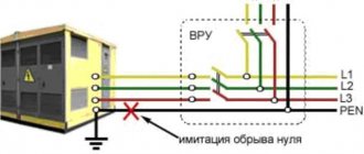
to ground the cable armor for its safety and the safety of everyone who is near the cable: these are steel strips that conduct current. This means that if such a cable is damaged (or it rots on its own like the lower sample), then dangerous voltage will appear on the armor, which the protection (default protection - I remind you of the post about RCD or short circuit protection - automatic) must be turned off. For the protection to work, it is necessary to create a path for leakage current or short circuit current. This means that the cable armor must be connected to the PE.
In old projects (multi-apartment residential buildings with gas), the working zero N O_o was transmitted through the cable armor (or its outer metal sheath). This can no longer be done: now all armor must be connected only to PE!
The armor is grounded at both ends of the cable. If an armored cable connects two large buildings (House and Bath), then each building must have its own ground loop! If an armored cable powers a small shield of a conventional gazebo or shed, then in the shield the armor is connected to the PE core of the same cable.
However, don’t you dare transmit PE over your armor! PE must be transmitted through a cable core whose cross-section is designed to withstand the short-circuit currents for which the cable is designed!
Previously, armor was soldered, welded, or simply pulled out one of the strips and screwed it to the PE/PEN busbar in the shields. Now there are technologies that are more elegant and easier to install - Constant Pressure Springs, which I will talk about in this post.
I cannot say that the cable armor is resistant to all external physical influences and such a cable cannot be broken with a shovel. It’s possible, and how (of course, it depends on the cross-section). The same VBBShV 3x10 that we bought for commissioning in 2010, my Partner then hacked it with a chisel and a hammer. I remembered this well, because I thought that the armor should be more resistant.
Small cross-section cables can be cut with cutters or powerful wire cutters. For professional cutting of large cross-section cables, there are special pruning shears. If you need to cut the cable once, then all means are good: from an angle grinder to a reciprocating saw.
We cut the armored cable with harsh cutters
You can lay the cable in the ground directly as is, if you know that you will not change it and, in case of damage, bury it in the ground - for example, VBShV 3x1.5 for small landscape lamps among the bushes on the site.
If you want to do everything even more severely and competently, then the cable should be laid in pipes: this will additionally protect it and make it possible to replace it. Most people use HDPE water pipes as pipes.
However, for proper installation, there are special double-wall pipes for electrical wiring from the booster compressor station:
Double-wall flexible pipes DKC for underground installation of electrical cables
I prepared the material for this post at the beginning of the year, but I doubted whether I cut the samples correctly. And then, just at the beginning of summer, ETM had another forum-party in the format of an exhibition. And ETM was also 30 years old. On this forum I hung out with everyone I knew (and then I sat down with the ABB people and started making fun of people there who came up and asked something about shields).
So I saw the guys from KVT and asked them all the questions.
Exhibition stand and personnel of the KVT manufacturer at the ETM 30 Years Forum
They had the most interesting stand, since you could touch and feel everything.
Exhibition stand and personnel of the KVT manufacturer at the ETM 30 Years Forum (samples of KVT products)
The guys explained to me that I had done everything correctly and gave additional information on how to properly terminate the cables so that moisture did not get into them. And now I can tell you everything!
KVT PPD springs (Constant Pressure Springs) and armor grounding with their help.
So, we are talking about a task that applies to my switchboards that I assemble: up to 63A, single-phase or three-phase, with cable cross-sections up to 16..25 sq. mm. In most of these projects, armored cables will be used for the Network/Generator inputs and power panels of other buildings. The armor of these cables must be grounded inside our shields (and connected to the busbar or PE terminals).
What does it mean? That the grounding of the armor should be compact (so that it fits into the shield and there is no need to leave half a meter of space in height for cutting and soldering) and technologically advanced: welding and soldering are inconvenient for a clean and beautiful shield on the terminals (I remind you of the assembly post about terminals in shields).
For this, KVT (and other manufacturers, but I love KVT) offers the following components (links lead to the KVT website):
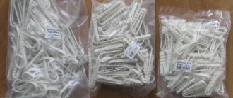
- PPD springs - Constant Pressure Spring . _ This is what I'm talking about: special springs that tightly press the ground wire to the steel armor strips of the cables. They are convenient and easy to install, and take up little space in the panel.
- fabric PML - P braided Copper Tinned . This is a flexible flat braid (I ordered PML-10-1000 - for 10 squares and 10 meters), which is convenient to press with the flat part to the steel armor strips. At the other end, the braid can be gathered into a bundle and terminated with an NShVI or TML tip.
You can buy them in bulk (in packs of 50 pieces) anywhere, and individually - for example, at ElektroMontazh (they also have PML braiding).
(added to the post) Of course, KVT has a lot of tools for terminating cables: these are end couplings (they also include PPD springs) and heat-shrinkable gloves (here is a link to the KVT catalog on their website). If you want (and their nomenclature suits your range of sections), then use them. An example of such products is on my collage:
Examples of cable terminations and heat-shrinkable gloves (photo from the KVT website)
The idea of PPD springs is very cool and simple. These springs are made of a special steel strip that springs and tends to curl into a tight roll. We roll this roll around the cable armor tapes and use it to tightly press the PML grounding braid. And since it is a spring, it continues to press on this connection, providing electrical contact.
The main points for installing springs will be as follows (below in the post there will be all the installation photos):
- Before winding the spring, the armor tapes must be cut so that they have a distance from the edge of the cable cut that is approximately 5 mm larger than the width of the PPD spring;
- All dirt from the armor must be sanded off so that the armor is shiny and has good contact;
- If you want, you can use contact paste, which improves contact and protects it from moisture and oxides;
- We secure the PML grounding braid twice: once we apply it to the armor and press it with a spring, and the second time, after making several turns, we bend it and again press it with a spring so that the braid does not break out when installing the cable. For this purpose, it is necessary to leave a gap along the armor strips, so that the bent section of the PML braid (it will protrude beyond the edge of the spring after the second bend) has somewhere to rest, and it does not hang in the air.
PPD springs are selected according to their dimensional grid. I copied the sign from the KVT website:
| Type | Width | Diameters |
| PPD-0 | 10 mm | 8-15 mm |
| PPD-1 | 16 mm | 12-25 mm |
| PPD-2 | 16 mm | 16-32 mm |
| PPD-3 | 20 mm | 19-45 mm |
| PPD-4 | 20 mm | 26-60 mm |
| PPD-5 | 20 mm | 36-80 mm |
| PPD-6 | 20 mm | 50-110 mm |
IMPORTANT! Do not forget that you need to select PPD springs not according to the outer diameter of the cable, but reduce it by the thickness of the external insulation (by 2-3 mm): after all, the spring will not be wound onto the cable, but onto the tapes of its armor, and it should not be there hang out.
For example, the VBShV 3x4 cable has an outer diameter of 14 mm. We reduce it by 3 mm and get 11 mm. This means we need a PPD-0 spring. And the VBShV 5x16 cable has an outer diameter of 28 mm. We reduce it by 3 mm and get 25 mm. This means we need a PPD-1 or PPD-2 spring.
Here, look at the photo below, in which the outer diameter of the cable seems to fit a spring with a number larger than it is required for the diameter of the cut part of the cable where the armor is located:
Selection of KVT PPD springs according to the internal diameter of the cut VBSHV cable
In this part of the post, I will show how to cut and ground the cable armor inside the shield - where protection of the cable cutting area from moisture is not required.
We arm ourselves with cables (the upper one is VBShV 5x4, the lower rotten one is VBShV 3x2.5), PPD springs (PPD-1 for the upper cable and PPD-0 for the lower one) and pieces of PML braid.
Kit for grounding cable armor: PPD springs and PML braid
First, let’s finish our braids (I remind you of the post about tips and the KVT tool):
The PML braid is terminated with tips of the required type (NSHVI and TML)
PPD springs look like this:
KVT PPD springs for grounding cable armor
On the side of the spring there is its number (model number) in the form of a number (you saw it in the photo where I showed how they relate to the diameters of the cables).
So that the spring can be conveniently wound around the cable armor, it has a small tongue. You can use it to pull back the spring and start winding.
The KVT PPD spring is very dense and is rolled in several layers from the factory
Carefully! The spring is sharp (since it is stamped) and can cut your hands!
Let's take care of our cables. First, let’s unwind both armor tapes (it’s also sharp, be careful):
Cutting the VBSHV cable: Unwinding the armor tapes with pliers
Now let's cut them so that they can be wound back, and we have an even cut of the armor in a circle. To do this, you need to cut at an angle, or immediately try on the cut in place like this:
Cutting the VBSHV cable: We cut the armor strips at an angle so that they lay in an even cut
After this, tightly (I used pliers) we wind the armor tapes back, obtaining a flat surface for our spring:
Cutting the VBSHV cable: We wrap the cut armor tapes around the cable core
Now we take our grounding braid, place it on the armor tape and press it with a spring like this:
Installing the PPD spring on the cable: Hook the edge of the spring onto the metal armor tapes
And then we blur the spring, pressing it tightly against the armor and braid:
Installing the PPD spring on the cable: We begin to unwind the spring, pressing the PML braid with it to the cable armor
Let's repeat the same thing with the rotten cable. We cut the armor (here it turned out better and more beautiful - I learned it) and clean it with sandpaper until it shines:
If the armor strips are rusty and dirty, they must be sanded
We prepare the braided wire and spring (the armor tapes are tightly laid using pliers):
The armor strips are sanded to a shine. The cable is ready for armor grounding
First, we wind the first layer of spring from the braid, and then we bend our braid and wind the second layer of the spring. Like this:
The process of installing the PPD spring on the armor of the VBSHV cable for grounding it with PML braid
We do the same on the first cable:
The PML braid is bent and pressed again with a spring to make contact more reliable
All the photos show how the spring rests on the armor and how it presses our braided wire. That's all the installation tricks!
We received our cables with grounded armor, yay:
VBSHV cables, cut for internal installation in a switchboard (without moisture protection)
Termination and grounding of armor of VBSHV (AVBSHV) cables for outdoor conditions with moisture-proof connections.
What was described above applies to the cutting of cables in dry panels or places where they are protected from moisture: input panels on poles or walls (IP65), inside panels that are located indoors. But what if you need to cut the cable on the street (or even in a lamppost)? But now we’ll find out, and I asked KVT about this.
The main idea of cutting cables is to prevent moisture from getting under the cable sheath. The theses and installation principles here will be as follows:
- Moisture flows from top to bottom. Since the cable is usually inserted from below (from the ground, since it was created to be buried there), moisture can get into its cut end, which is directed upward. Moisture can also flow through the PML braid, since the braid has a porous structure. Therefore, it is necessary to protect both the cable cutting site itself and the braided wire if it extends upward from the cutting site.
- To protect the cutting area, heat shrink with an adhesive layer is used. At KVT it is designated TTK (here is a link to their website).
- For the base for heat shrinkage, a special mastic sealant is used. For KVT this is KG-R (sealant kit on a roll). The sealant is made in the form of a tape, a piece of which is cut off and tightly wrapped around the place where the armor is cut and grounded with a PPD spring.
- To prevent moisture from being pumped through the PML braid, it must be soldered in the place where it will come out of the heat shrink and the cable cutting area. I couldn’t do this in the photos, since I worked without special fluxes, just like that. People in the comments advised to also soak it with silicone sealant - it also works.
In my example, I dug up a heat-shrinkable tube KVT TTK (4:1)-32/8, which has an initial diameter of 32 mm and shrinks up to 8 mm, from the availability in ETM. And it successfully matched the example of installation of both of my sample cables.
Set of sealant in tape (KG-R) and heat shrink with an adhesive layer for cutting VBSHV cables with moisture protection
First, we do everything the same as last time: we cut the armor (this time with the correct margin), sand it for good contact, install the PPD springs and the PML grounding braid: on one cable with the lead up, and on the other with the lead down .
Before protecting the end of the VBSHV cable from moisture, the PPD spring is installed on it in the usual way
Where the PML braid will come out from above, we must solder it so that in this place it does not allow moisture to enter our cutting area:
Soldering the end of the braid with PML (solder) at the exit point (so that water does not penetrate into the cable)
As I wrote above, I was unable to do this: my torch oxidized everything, and ordinary soldering solder did not fit here. In theory, you need to use some kind of flux that will remove these oxides. If anyone knows, please write in the comments to the post.
After everything is ready, cut off a piece of heat shrink and sealant. The sealant must be cut off so much that it can completely cover the PPD spring itself and the area around it. My cables are “children’s”. If you will be cutting cables with a larger cross-section, apply the sealant in two strips so that they overlap each other.
A prepared set of KG-R sealant and heat-shrinkable tube with an adhesive layer for sealing the VBSHV cable
The sealant is very soft and easily creased, adhering to the cable, spring and inner sheath of the wires. It really stinks like some kind of crap.
We wrap KG-R sealant tape around the installation site of the PPD spring on the armor of the VBSHV cable
We make dolls from our springs and cutting points:
Both VBSV cable termination points are ready for insulation using heat shrink
And then we put on the heat shrink:
Heat shrink with an adhesive layer is placed on the VBSHV cable termination points
And we warm it with a burner, sitting it in place:
We compress the heat shrink with a torch in order to finally seal the place where the armor of the VBSHV cable is cut and grounded
The glue on the heat shrink melts, filling all the voids between the tube and the cable:
You can see how the adhesive layer on the heat shrink melts, sealing the connection
After all the cutting, the following structures are obtained, ready for work:
An example of cutting, terminating and grounding armor of VBSHV cables for outdoor use
The glue from the heat shrink came out and sealed everything (except for the place where the PML braid came out):
The glue came out of the heat shrink (with the adhesive layer) and sealed the cable cutting area
Thus, the most important thing is to properly seal and lead the PML braid out so that water does not get through it into the cable cutting area. As I already said, this place needs to be soldered and additionally sealed with sealant.
Cooperation with Cablestar
If you need it, just call our company and place an order. We have a large selection of high-quality cable and wire products. In stock you can find VVGngLS cables, (including) and other brands of wires. If you need detailed professional advice, the company’s specialists are ready to provide it. Contact us by phone or leave requests on the website, online, and consultants will help you choose the appropriate cable, as well as place your order. We always focus on the needs and preferences of our clients.
In our company, favorable terms of cooperation await you. We offer all customers the best prices and guarantee full compliance of cable and wire products with all declared properties and characteristics.
the site responds
2.3.71. Cables with metal sheaths or armor, as well as cable structures on which cables are laid, must be grounded or neutralized in accordance with the requirements given in Chapter. 1.7.
2.3.72. When grounding or neutralizing the metal sheaths of power cables, the sheath and armor must be connected by a flexible copper wire to each other and to the housings of the couplings (end, connecting, etc.). On cables of 6 kV and above with aluminum sheaths, grounding of the sheath and armor must be carried out with separate conductors. It is not required to use grounding or neutral protective conductors with a conductivity greater than the conductivity of the cable sheaths, however, the cross-section in all cases must be at least 6 mm 2. The cross-sections of grounding conductors of control cables should be selected in accordance with the requirements of 1.7.76-1.7.78. If an external end coupling and a set of arresters are installed on the structure support, then the armor, metal shell and coupling must be connected to the grounding device of the arresters. In this case, using only metallic cable sheaths as a grounding device is not allowed. Overpasses and galleries must be equipped with lightning protection in accordance with RD 34.21.122-87 “Instructions for the installation of lightning protection of buildings and structures” by the USSR Ministry of Energy.
2.3.73. On oil-filled low-pressure cable lines, the end, connecting and locking couplings are grounded. On cables with aluminum sheaths, feeders must be connected to the lines through insulating inserts, and the housings of the end couplings must be insulated from the aluminum sheaths of the cables. This requirement does not apply to cable lines with direct input into transformers. When using armored cables for low-pressure oil-filled cable lines in each well, the cable armor on both sides of the coupling must be welded and grounded.
2.3.74. The steel pipeline of oil-filled high-pressure cable lines laid in the ground must be grounded in all wells and at the ends, and those laid in cable structures - at the ends and at intermediate points determined by calculations in the project. If it is necessary to actively protect a steel pipeline from corrosion, its grounding is carried out in accordance with the requirements of this protection, and it must be possible to control the electrical resistance of the anti-corrosion coating.
2.3.75. When a cable line transitions into an overhead line (OHL) and if there is no grounding device at the overhead line support, cable couplings (mast) can be grounded by attaching the metal sheath of the cable, if the cable coupling at the other end of the cable is connected to a grounding device or the grounding resistance of the cable sheath complies with the requirements of Chapter. 1.7.
An electric cable with a protective cover of metal tapes or one or more layers of metal wires is called armored (GOST 15845-80). This is a fairly effective way to protect conductors from mechanical damage and from destruction under the influence of temperature, moisture and ultraviolet radiation. In order for the equipment to serve for a long time and trouble-free, the laying of armored cables must be carried out in accordance with all the rules. The requirements for carrying out such work are set out in the “Rules for the technical operation of power plants and networks of the Russian Federation”, approved by the Ministry of Energy of the Russian Federation on June 19, 2003 and mandatory for execution throughout the Russian Federation.
Grounding an armored cable is a necessary condition for safe operation and maintenance of the cable line. Current regulatory documents require that all conductive parts of conductors be grounded.
Cable armor grounding device according to PUE rules
In accordance with the electrical installation rules (PUE) for cable armor, grounding is mandatory. The circuit includes other components of the product and supporting structures. The regulations established by the regulatory document for the implementation of protective measures in relation to main energy pipelines are aimed at the stability of the electrical supply. There are differences in design between armor protection in a cable channel, room and ground.
Grounded elements of the main line
The insulated cores of the cord are covered with metal sheaths and steel tapes in order to protect the transmission medium from mechanical damage, exposure to moisture, temperature and ultraviolet radiation. The rules require that all current-carrying parts of cable electric lines (CEL) be grounded. Brands of armored products contain the letters in the encrypted name: B - protection made of steel tape (AVBbShv, AAB2l); K - from round wire of an iron-carbon alloy (PvKShp, ASKl); P - from flat wire rod of the same material (AAPL).
Some protected cables are made in a different version - instead of steel armor, they are covered with an aluminum or lead sheath (AAShv, ASShv). This product with a modified design is inferior in strength, but is more resistant to aggressive environments and corrosion. The cables are also equipped with a shielding layer against electromagnetic radiation and to equalize static potential. The braiding material is aluminum wire or foil. The following are subject to grounding:
- metal shell of a group of power cores, armor and screen of the control cord;
- connecting coupling when splicing construction-length products;
- conductive structures of KEL: gallery, tray, box;
- cable supporting the line;
- a metal pipe that serves as a channel for armored cable in a room.
Protected cable lines must have a grounding loop according to the Electrical Regulations on both sides of the line. This requirement applies to branches longer than 200 m.
Grounding conductors for cable armor in the ground
The laying of main power supply lines in the ground depends on the properties and composition of the soil layer being opened .
In permafrost areas, places with rocky and unstable soil, a cable with wire armor is laid, in pliable, stable soil - with steel tape. Before placing the line in the trench, it is necessary to inspect the product along its entire length for the integrity of the shell. Current protection of the armor is carried out with a flexible, non-insulated wire.
The table shows the ratio of the cross-sections of the cable cores (top line) and the ground electrode (mm²):
1.7.85
Protective electrical separation of circuits should generally be applied to one circuit.
The maximum operating voltage of the separated circuit should not exceed 500 V.
The power supply for the separated circuit must be supplied from an isolation transformer that complies with GOST 30030 “Isolation transformers and safe isolation transformers”, or from another source that provides an equivalent degree of safety.
Current-carrying parts of the circuit powered by an isolating transformer must not have connections with grounded parts and protective conductors of other circuits.
It is recommended to lay conductors of circuits powered by an isolation transformer separately from other circuits. If this is not possible, then for such circuits it is necessary to use cables without a metal sheath, armor, screen or insulated wires laid in insulating pipes, boxes and channels, provided that the rated voltage of these cables and wires corresponds to the highest voltage of the jointly laid circuits, and each circuit protected from overcurrent.
If only one electrical receiver is powered from an isolation transformer, then its exposed conductive parts should not be connected either to the protective conductor or to the exposed conductive parts of other circuits.
It is allowed to power several electrical receivers from one isolation transformer if the following conditions are simultaneously met:
1) open conductive parts of the separated circuit must not have an electrical connection with the metal body of the power source;
2) open conductive parts of the separated circuit must be connected to each other by insulated ungrounded conductors of a local potential equalization system that does not have connections with protective conductors and open conductive parts of other circuits;
3) all socket outlets must have a protective contact connected to a local ungrounded potential equalization system;
4) all flexible cables, with the exception of those supplying equipment of class II, must have a protective conductor used as a potential equalization conductor;
5) the shutdown time of the protection device in the event of a two-phase short circuit to open conductive parts should not exceed the time specified in Table 1.7.2.
Signal Wire Shielding Methods
The signal wire (cable) is used to connect various elements (components) of the system. Most often, the signal wire contains several pairs of conductive wires with polyethylene insulation, as well as with a PVC sheath. Some types of signal wires have a special shield to protect against electromagnetic interference and are called “shielded signal cables.”
Shielding Signal Wires
Shielding is the protection of a signal wire from noise or unwanted signals.
Signal wires have high quality signal transmission due to their shielding and twisted pair construction to ensure better matching of their longitudinal impedance and ground impedance. At high frequencies, common-mode interference can occur due to the difference between the length of the wires and the frequency characteristics of their impedances.
Signal wire shielding methods take into account the path of interference.
To completely eliminate the adverse effects of parasitic capacitive coupling, an electrostatic screen made in the form of a conductive tube is used. In this case, it is correct to ground the electrostatic shield only from the side of the signal source. In Fig. Figure 1 shows how to improperly ground an electrostatic shield.
In Fig. Figure 2 shows hybrid grounding, which is the most popular method when transmitting a broadband signal from a distant source with high resistance.
Making a screen that will reliably protect against parasitic inductive couplings is much more difficult than a classic electrostatic screen. For manufacturing, you need a material with increased magnetic permeability. In addition, the thickness of such a screen should significantly exceed the thickness of electrostatic screens.
For frequencies less than 100 kHz, it is possible to use steel screens or screens made of permalloy (an alloy of iron and nickel). For higher frequencies, screens made of copper or aluminum are suitable.
Since shielding the magnetic component of interference is difficult, special attention must be paid to reducing the inductance of the signal cable and selecting suitable receiver and transmitter circuitry. In Fig. 3, 4, 5 and 6 show connection diagrams for the amplifier and screen, providing different rms noise amplitudes.
For most, for example, temperature sensors, the signal sources do not have a protective ground, and therefore an electrostatic shield is used along with a differential amplifier and output resistors. The screen grounding diagram in this case is shown in Fig. 3.
Double shielding of long cable
A double shield (Fig. 7) is used to improve the quality of shielding over a wide frequency spectrum. The internal screen is grounded on one side (the signal source) to prevent the passage of capacitive interference, while the second, external screen, is used to reduce high-frequency interference.
In any case, to prevent accidental contact of the screen with metal objects and the ground, it must be insulated.
In the case of a long cable, even with proper grounding, interference still passes through the screen, and therefore it is better to transmit the signal over a significant distance or with serious requirements for measurement accuracy either in digital form or via a fiber-optic cable. For this purpose, analog input modules with a digital RS-485 interface or fiber-optic converters of the RS-485 interface can be used.
Galvanic isolation
The above problems can be radically solved using galvanic isolation (Fig. with separate grounding of the digital, analog and power parts of the system. That is, the signal between electrical circuits is transmitted without contact between them.
Features and color of electrical wires
Painting in a variety of colors is needed to make it easier to distinguish conductors during installation of a multi-core cable. It may be noted that a couple of decades ago, color marking did not matter. Nowadays, most people adhere to the meaning of wire according to color scheme in everyday life.
There are cores running through the cable, each of them has its own purpose and its own characteristic color. With the current variety of colors, installation work is easy and calm. Coloring is a useful feature to avoid dangerous and unnecessary mistakes. The state has established rules and regulations for labeling:
- The phase is indicated by a red, black, gray or brown tint.
- The neutral conductor is identified by blue color.
- The ground (ground wire) is yellow-green in color.
In addition to the color difference of the cable, there is also a marking indicated by letters:
- N - neutral or middle conductor;
- PE - zero (protection);
- PEN - classic combination of wires, combined zero;
- L - phase conductor.
From time to time, three-core cables at home are laid from flat conductors of the same color; they are often made in white. In this type of use, the core running through the middle will be considered grounding. Manufacturers often designate the insulation of the ground conductor in yellow and green. It is also possible that the yellow-green coloring will be applied transversely.
When performing repair work yourself, it is advisable to choose what color the ground wire will be and use a marker to apply the selected color to the wiring yourself for easy identification of cables in the future. As an alternative to a marker, you can use silicone tubes of the desired color; they are sold in almost every electrical store.
Having decided what color the grounding wire will be, you need to select the material for making the core. For grounding in domestic conditions using a stranded or single-core wire, it is necessary to use copper conductors. The cross-section of the grounding cable is selected in accordance with the requirements of the home network.
Grounding of cable trays: elements, requirements and application features
At the stage of commissioning cable routes, electricians take some measures to increase the safety of the equipment. Such actions include grounding cable trays.
There are many types of trays, differing in the type of grounding. The most common type of trays is wire. They must be installed in accordance with the conditions set out in GOSTs and PUE (Electrical Installation Rules).
Some inexperienced users feel that connecting trays with screws ensures cable continuity. However, reliable metal communication, which is judged by voltage conductivity, is not achieved in all electrical installations. The route refers to grounding conductors only if there are additional jumpers or in the case of connecting trays according to certain standards. The connection requirements are set out in GOST 10434-82.
To simplify orientation in the grounding system, the jumpers should correspond to a certain color scheme. Most often we are talking about a combination of green and yellow colors. The cross-section limits are set from 4 to 6 square millimeters.
When organizing grounding using self-made jumpers, one should not forget about an important rule: the ends must be processed. Processing means crimping. The screws for fixing the protective conductors cannot be used to solve other problems, for example, for joining the tray end or mounting on a support.
In some product modifications, screw hardware for trays are equipped with washers or nuts. These elements have a “scratching” surface. Thanks to this feature, more reliable electrical contact is ensured, since the risk of loosening fasteners is significantly reduced. Small copper plates are also used (they are also called busbars).
Grounding systems (GS)
According to the main provisions of the PUE, the grounding of electrical installations and working equipment can be organized in several ways, depending on the neutral connection circuit at the transformer substation.
Based on this feature, there are several types of grounding systems, designated in accordance with generally accepted rules. Their classification is based on a combination of the Latin symbols “T” and “N”, which means the transformer neutral grounded at the substation.
The letters “S” and “C” added to this designation are abbreviations from the English words “common” - common gasket and “select” - separate. They indicate the method of organizing the grounding conductor along the entire length of the supply line from the substation to the consumer (in the first case - a combined PEN, and in the second - separate PE and N).
Combined with a hyphen “CS” means that on some part of the route the grounding conductor is combined with the working “zero”, and on the remaining section they are laid separately.
Nature and nature of interference
The frequency range of interference, its magnitude varies over a fairly wide range. Static electricity discharges amount to milliamps. And lightning strikes cause hundreds of kiloamps. To this are added industrial frequencies at short circuit currents (SCC). Their rapid growth under the influence of lightning or radio transmitting devices reaches several gigahertz. Such conditions create a very harsh electromagnetic environment (EME).
Electromagnetic interference affects various objects. The nature of dissemination and influence manifests itself in several ways. The impact is carried out on the body of a particular equipment through radiation. Through analog or digital interfaces and grounding ports, interference can enter the devices.
Often microprocessor equipment is surrounded by open switchgear (OSD), power buses and apparatus. In such places, the amount and magnitude of interference increases significantly. The main source of impact is switching in power networks, affecting secondary circuits.
The nature of the connections between secondary circuits and high-voltage systems is determined by their mutual location. The design of highways with secondary circuits must take into account geometric relationships. However, everyday practice leads to many cases of violation of this condition. This happens due to contradictions with other regulatory requirements.
In many of these situations, circuit shielding provides protection against interference. But such an operation is not able to solve all the problems of neutralizing the negative impact. For more reliable protection, you cannot do without grounding the screens. They are designed to reliably separate the conductors of one electrical circuit from the effects of other circuits and electromagnetic atmospheric phenomena.
Electrical Safety Protective Measures
If you strictly follow all the rules during operation, the use of electrical appliances does not pose any danger. Protection against electric shock is achieved in the following ways:
- the part of the electrical circuit through which the current passes must not be accessible to accidental touch;
- live parts that are open must not contain voltage dangerous to human life, even if the insulation is broken;
- such inaccessibility is achieved through protective shutdown, the use of low voltage, double insulation, equalization and potential equalization, the implementation of barriers, and the location of electrical equipment outside the accessibility zone.
The use of measures in combination to protect against electric shock should not reduce the effectiveness of each.
If the electrical equipment is located in the potential equalization area, and the highest operating voltage is no higher than 25V AC and no more than 60V DC, then there is no need for protection against direct contact.
Also, the protective functions of electrical equipment must be provided during the manufacture of the latter, or during installation.
Design
We’ve sorted out the approximate decoding of the markings, now let’s move on to considering the general design of armored cables. It consists of:
- A conductor made of aluminum or copper.
- A layer of insulation over the core, usually PVC, polyethylene or impregnated paper.
- Next comes a screen made of copper wires or various conductive tapes, for example, metal or conductive cardboard and paper.
- On top of the screen is another layer of insulation.
- Then comes a layer of armor, usually made in the form of tapes, then the top tape is applied so as to overlap the joints of the turns of the bottom tape. Tapes like a spiral on a cable.
- may in the center of the cable ; it can be a steel rope or a fiberglass rod, coated or uncoated. It plays a load-bearing role and relieves mechanical stress from the cores.
A special end coupling for an armored cable is installed at the end - it is needed to ensure that the layers of insulation and protection of the cable remain intact and safe, and the cores are separated from each other and reliably insulated.
End coupling, on the left you can see the grounding conductor for the armor, the conductors are separated and insulated, insulators are put on them
To connect building lengths of armored cables or connections during repair work in case of damage, they are also made in couplings, which are usually filled with bitumen or other dielectric solutions. More specifically, this point depends on what voltage the cable is designed for; the higher the voltage, for example 6-10 kV distribution networks, the more stringent the requirements for connections and insulation. At high voltages, the presence of air in the connection can be detrimental, as it ionizes, resulting in the development of discharges.