When repair and electrical installation work is carried out, there is often a need to quickly check for the presence of voltage in individual sections and elements of the electrical circuit. Also, quite often there are cases when you urgently need to make sure that there is reliable contact between different elements (parts) of an electrical circuit. The easiest way for such checks is special phase indicators, which are familiar to everyone, even a person completely far from electricians. Devices that allow you to “ring” a circuit are also often used; they are also called samplers
.
The sampler
is quite a convenient thing.
It takes up almost no space, and is also quite simple and reliable to use. The phase indicator
usually looks like an ordinary screwdriver with a simple electrical probe. The indicator circuit consists of series-connected resistors and a neon light bulb. When measuring a circuit for the presence of a phase, you should also connect the person’s own resistance by touching the contact located on the handle of the screwdriver with your finger. Below are 3 options for indicator screwdriver circuits.
LCD phase indicator circuit
It is worth separately noting several features that you should definitely remember when working with an indicator screwdriver:
Under certain conditions, the neutral working wire may become live and therefore should not be touched when working on the circuit. You can make sure that there is no voltage on the wire quite simply, just use an indicator screwdriver.
There are cases when the indicator turns out to be faulty (there are many examples, but let's say a light bulb burns out), and then it will show you the missing voltage. Therefore, we urge caution - be careful and always check the indicator before working in areas where voltage is known to be present.
An indicator screwdriver is needed only to determine whether there is a phase (potential) in a certain section of the circuit, and this cannot in any way tell us that there is operating voltage on the circuit between ground and phase. In the event that the wire of the “ground” indicator breaks (for example, is damaged), the indicator will definitely show you the presence of a phase, but the circuit itself still remains broken.
Also note that you should work especially carefully in bright sunlight (for example, in direct sunlight). In such lighting, the neon light of the bulb is almost impossible to see, and therefore you can easily make a mistake when determining whether phase voltage is present.
Before you start working with the socket of a chandelier or any other lighting fixture in your apartment, do not rely on the light switch (since the button is at the bottom, it must be “off”), but always check the presence of voltage with an indicator screwdriver. To do this, it is worth checking the central terminal of the socket and the contact that connects to the lamp base.
But there is a much more functional electrician's probe. This is a two-band voltage indicator, thanks to which you can check not only the presence or absence of voltage between different parts, but also between the “ground” and the parts. Unlike an ordinary indicator screwdriver, the two-line indicator has an auxiliary probe connected to the main unit using a meter cord. This probe is needed to be able to determine the voltage between points in the circuit.
Speaking of probes, it is perhaps worth including here the simplest one, which consists of a connected battery and a light bulb. The old name of this device is “Arkashka”. With the help of such a fairly simple device, you can “ring” absolutely any section of the circuit under study. Let's say this can be useful when you need to make sure that there are no breaks in the electrical circuit.
indicator lamp has also survived to this day.
.
By the way, it is prohibited by the rules of the PUE
.
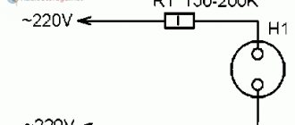
But today, many specialists have learned to circumvent these requirements by using a lower-power light bulb in the device (15 W, like in a sewing machine or refrigerator), which is placed in a special transparent case. Measuring technology
During electrical installation work, a phase indicator is often required. Previously, such devices used gas-discharge indicator lamps; today, instead of them, high-brightness LEDs can be used, which glow noticeably at a current of several tens of microamps. Galvanic isolation can be provided by capacitive coupling of the indicator with the user’s hand.
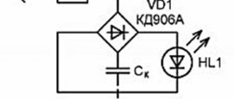
The diagram of the proposed phase indicator is shown in Fig. 1. Phase voltage
It is supplied to the diode bridge VD1 through the current-limiting resistor R1 and the structural capacitor CR. The rectified voltage is supplied to the HL1 LED, and it lights up, thereby indicating that the wire being tested is indeed a phase wire. The indicator is mounted in a plastic pen housing of a suitable size. The capacitor Sk is formed by a piece of aluminum foil rolled into a cylinder and glued to the inner surface of the housing and the user’s hand. The dielectric spacer of the capacitor is the housing wall.
A variant of the indicator design is shown in Fig. 2. A pin (probe) 1 is inserted into the tip 2 of the pen body - a metal rod with a diameter of 1.5...2 and a length of 20...25 mm, to which a current-limiting resistor 4 (R1) is soldered. The rod is fixed in the tip with epoxy glue 3. Instead of the button (or inside it), an LED 9 is installed in the housing cap 8, to the terminals of which a diode bridge 7 is soldered.
One of the free terminals of the diode bridge is connected by a thin insulated iron three times larger than the internal diameter of housing 5, and the length is 10.15 mm shorter than the length of its internal cylindrical part. To ensure reliable contact, the end of the wire is stripped to a length of 30.40 mm, wrapped several times with the edge of foil and clamped tightly with pliers. The foil is then rolled into a cylinder and glued to the inner surface of the housing.
When selecting a case, you should choose one with a larger diameter and thinner walls - this will provide a larger capacity of the structural capacitor. To increase its capacity, the indicator body should be held in the hand as tightly as possible, the brightness of the LED will depend on this.
The current flowing through the capacitor Sk in this design is very small (only a few microamps), so not every LED will glow noticeably. To make the indication more noticeable without increasing the current through the device, a relaxation generator based on a symmetrical DB3 dinistor or similar can be introduced into it (Fig. 3). In this case, when the probe touches the phase wire, capacitor C1 is first charged, and when the voltage across it reaches approximately 35 V, the dynistor opens and a current pulse flows through the LED, causing a flash of light, which is clearly visible. The frequency of flashes depends on the capacitance of capacitors Ck and C1: with an increase in the capacitance of the first of them, it increases, and of the second, it decreases. The generator parts are mounted directly on the terminals of the diode bridge.
A further increase in the brightness of the light signal is possible by increasing the current through the LED. To do this, the capacitor Sk is replaced with resistors R1, R3 (Fig. 4) and contact E1 (preferably made of metal with a stainless coating) is installed on the outer surface of the indicator body, electrically connected to the first of them. In this case, the foil is not needed; the relaxation generator on the VS1 dinistor can be left or eliminated (i.e., connect the LED directly to the terminals of the diode bridge). The appearance of the indicator is shown in Fig. 5.
The device uses resistors MLT, S2-23, ceramic capacitors K10-17v. A symmetrical DB3 dinistor can be found in a failed compact fluorescent lamp (CFL), and 1N4007 diodes can be removed from it to assemble a rectifier bridge to replace the one shown in the diagram. LED - any increased brightness in a housing with a diameter of 3.5 mm. It should be selected according to the brightness of the glow at low current. To do this, the existing LEDs are alternately connected to a 12 V power source through a 100 kOhm resistor and an instance with maximum brightness is selected.
Or a switch in an apartment, you need to have a phase indicator on hand. These devices differ in generator power. The models also have their own frequency and threshold resistance. There are quite a few phase indicators on the market.
They are produced with two or three clamps. The duty cycle of the models does not exceed 90%. When choosing a modification, it is important to pay attention to the protection class. In order to learn more about phase indicators, you need to consider the device diagram.
Homemade modification
If necessary, you can make an LED phase indicator yourself. First of all, a high-quality wire generator is selected for this. Its output voltage must be at least 12 V. You will also need a damper to assemble the device. There are different types on the market, and they vary quite a bit in sensitivity. If we consider a simple model, then it is more appropriate to select an element with a resistor. A microcontroller for the phase indicator will need a multi-channel type. At the end of the work, the LED is fixed, as well as the clamps.
Passive voltage and current indicators: operating features
The second sign of the classification of indicators is their division into active and passive devices. The basis is the functional features of the tools. Passive devices include those with the following characteristics:
- Not complicated. Single-pole, consist of one housing with elements placed in it.
- Limited functionality. The only thing that an indicator screwdriver of this type shows is whether there is voltage at a certain point in the electrical circuit.
- Unprofessional tool. Most often used in everyday life, it is unacceptable for electricians due to the lack of opportunities to provide the necessary inspection of the condition of electrically conductive cables.
The advantage of these indicators is that when determining the presence of voltage, a zero is not needed; its role is performed by a person holding an indicator screwdriver in his hands. The peculiarity of its device is also that the resistor, due to its significant resistance, does not detect the presence of voltage below 50 volts.
It is not difficult to understand how to find a phase with an indicator screwdriver of this type. You should touch the conductor with the sting, and press the plate on the device body with your hand. If there is voltage, the neon light will light up.
Passive indicators only determine the presence of voltage at a certain point in the electrical circuit.
Consumer reviews about the Extech DV25 model
The indicated phase indicators are produced with three clamps. In this case, the measurement accuracy is very high. The generator in the device is of the wired type. The maximum overload parameter is 3.3 A. The model has only one sensor installed. According to experts, it is not afraid of high humidity. To protect the device from voltage surges, capacitors are installed.
The model is ideal for home use. However, it is important to note that the conductors used are of short length. The model is not uniquely suitable for determining the phase in the power panel. According to experts, the battery is used at low power and only lasts for three hours. You can buy the presented phase indicator on the market at a price of 6,500 rubles.
How to check the phase without an indicator screwdriver
How to determine the phase without an indicator? There are several ways. They are sometimes the only way to correctly install a switch or replace a burnt out socket.
The first of them is the fastest, simplest and most reliable. It is based on a visual inspection of the wires. The fact is that the multi-colored braid is not random. It is the color that indicates neutrality or being under the phase of the vein. Remembering the correspondence is difficult, and it is not necessary. If necessary, just look at the marking table.
The second option allows you to determine the presence of voltage using the same control. One wire should be attached to the metal of the heating system, cleaned to a shine, and the other should touch the conductors where the phase needs to be determined. If you touch a live wire, the light bulb will light up. If you don't have an incandescent lamp on hand, you can use a neon lamp.
The third method, which tells you how to find a phase without an indicator screwdriver, may make you smile, since the diagram includes... potatoes. In addition, you will need two wires about 50 cm long and a 1 MΩ resistor. One cable must be connected to the heating metal, and the second cable must be probed for the core of interest. The ends of the wires must be inserted into the cut of the potato. If after a few minutes traces of darkening appear, it means the vein is phase. If not, then zero is determined. It is worth noting that the holding period should be 5, maximum 10 minutes. There is no point in drawing conclusions before the expiration of the extreme time threshold.
You can determine the phase without an indicator screwdriver by the color of the wire.
Opinion about Extech DV30 devices
This phase indicator (light) is very easy to use. It has three clamps in total. In this case, the generator is set to 3 A. According to experts, the capacitors used are of high quality. In total, the model has two sensors. Thus, the speed of phase determination is very high. The permissible humidity level is only 33%.
The capacitor in the device is of capacitive type. The operating frequency of the phase sensor is 500 Hz. In turn, the threshold resistance is 20 Ohms. The model is not suitable for working with power shields. However, when carrying out renovations in the apartment, it can be of great help. It is also important to note that the model has a calibration function. You can buy this phase indicator on the market for 6 thousand rubles.
Measuring instrument circuits
This section is devoted to the measuring and auxiliary equipment that is necessary for an amateur radio laboratory or workshop: various generators, ESR meters, auxiliary equipment necessary for a telemaster, homemade devices, and so on...
Homemade measuring instruments
Attachment to a multimeter for measuring ESR of capacitorsESR meter from a Chinese pointer instrumentSimple transistor tester (testing h21e)simple generator on OUAudio frequency generatorsActive probe for an oscilloscopeDouble-beam oscilloscope from a single-beamSimple ESR meter with a 1.5V power supplyRCL meterA device for checking battery parametersA device for measuring inductanceA device for testing capacitorsWhen boron for testing electrolytic capacitors Logic probe with a seven-segment indicator Device for determining turn-to-turn short circuits Device for testing field-effect transistors Indicator of bad contacts Capacitance meter for capacitors on an operational amplifier How to measure electromagnetic radiation with a multimeter Electric field indicator Frequency meter on an ATtiny2313 microcontroller Product length meter Substance identity meter Resonant frequency meter Oscilloscope from a TV Homemade counter GeigerRelay as a generatorSinusoidal signal generator on logic chipsLED oscilloscopeCapacitance meter and inductanceLC meter based on simple logicAmateur radio instruments for measuring inductanceGeiger counter made from a neon lampIndicator of high-frequency radiationMethodology for checking inductor or inductance for saturationPortable device for measuring resistance and capacitanceFM wave meterDetector for the presence of an audio signalTransistor probe with LED indicationLogic probe probeHigh-frequency generator (up to 15 mHz)Pulse generator triangular and rectangular shape Simple transistor audio frequency generator Device for testing transistors and diodes without desoldering LED transistor tester Universal measuring device Non-linear distortion meter Frequency meter - capacitance meter AC millivoltmeter Spark flaw detector Device for measuring soil humidity, temperature and illumination Wideband noise generator Function generator on XR2206LA borator audio frequency generatorA device for determining the parameters of a zener diodeThe simplest generator for TV repairThe simplest Ohm -meter Device for testing oxide capacitors without soldering Capacitance meter for capacitors Modification of the Ts435 avometer Probe generator for checking the radio receiving path Universal probe Light and sound probe Functional generator with electronic frequency tuning AF generator on the K174UN7 chip Tone pulse generator Capacitance meter - attachment for the DT-830B (M-830V) multimeter From battery capacity meterGenerator-probe for checking IF and AF paths Frequency meter from a radio receiver Device for testing remote controls Device for testing the functionality of quartz resonators Functional generator Logic probe without a power supply Operational amplifier tester Microvoltmeter for testing audio devices Digital voltmeter with LED indicator Periodic pulse generator LF generator based on K174UN7 Voltage indicator with automatic switching of measurement limits Phase meter G 50 Hz frequency generatorLogic probe with digital display
Schemes of industrial devices
Ts4317МTs4326 device Ts4342 device Ts4353Mastech М266F (C) circuitMastech MS2001Mastech m932Mastech MY6013 multimeterMastech MY61 multimeter circuitMastech MY62 multimeterMastech MY63 multimeterMastech MY64 multimeterMastech MY65mastech multimeter MY68Multimeter Mastech M300Multimeter Mastech M320Multimeter Mastech M3900Multimeter M830Multimeter MASTECH M-832Multimeter MASTECH M-838Multimeter MASTECH M-890Multimeter MASTECH MAS-830, 830L multimeter MASTECH MAS-838 multimeter MASTECH M 93 (93A) Multimeter DT9208A circuit and characteristics multimeter MASTECH M 9502 multimeter MASTECH MS 8220 circuit diagram multimeter MASTECH MS 8221 circuit diagram multimeter MASTECH MS 8222 circuit diagram Multimeters APPA107, APPA20 7 circuitOscilloscope OML-2MOscilloscope LO-70Teletest Laspi TT-03Generator GZ-118Oscilloscope VM556AOoscilloscope S1 -64Oscilloscope S1-49Oscilloscope S1-71Oscilloscope S1-73Oscilloscope S1-96Oscilloscope S1-103Oscilloscope S1-131Avometer (tester) Ts20. Scheme, improvements
Description of Extech DV45 models
This phase indicator has recently been in great demand. First of all, experts note its compactness. In this case, the holder is used with a rubber lining. The model has two clamps in total. The generator in the device is used at 4 A. The operating frequency of the phase indicator is 550 Hz. According to experts, the model is capable of carrying high current loads.
It is perfect for professionals. The capacitors in the device are of the pulse type. It is also important to mention a high-quality battery. The minimum permissible temperature of the presented phase indicator is -20 degrees. This device is not afraid of humidity. You can buy the model in the store for 7,200 rubles.
Tester. Operating rules
When and how to use an indicator screwdriver correctly, what are the requirements for the user’s personal safety?
Before checking hidden electrical wiring, the room should be de-energized. Exposed electrical wires should only be checked with a tester; do not touch them with your hands or conductors. Do not use the device in damp rooms, check the serviceability of electrical circuits with wet hands, the current passing through the body will be felt.
There should be no cracks, crevices or other damage on the tool body. If there is even minor damage, the device must be replaced. Repairing a damaged tester is not profitable; buying a new one will cost less.
Consumer reviews about the LUXEON EWR-5000 model
This phase indicator receives good reviews from customers. The device is ideal for home use. The model has three clamps in total. Its generator is of the wired type, and the element overload parameter is 3.5 A. Capacitors to protect the device are of the operational type. In total, the model has two sensors. The threshold sensitivity parameter is 5 mV. The operating frequency of the modification does not exceed 560 Hz.
The minimum permissible temperature of the phase sensor is -20 degrees. According to experts, the LED in the device rarely burns out. Also, the advantages of the model include high battery capacity. In offline mode it can work for more than 10 hours. The price of the presented phase sensor fluctuates around 6,500 rubles.
Types of voltage indicators: single-pole and double-pole devices
Modern industry produces a large number of different indicators. There is no specific standard classification for them. According to the characteristics of the technical device, devices can be divided into single-pole and double-pole, and they also distinguish between passive and active products. This section will discuss classification based on the first criterion.
Single-pole indicators. This type includes the simplest devices, the design diagram of which is described above: based on a tip and a neon lamp for indication. More advanced single-pole devices have an LED lamp, battery power, and an audible signal - in addition to the glow of the lamp. According to the principle of operation, such indicators are identical to the simplest devices, but it becomes possible to test the wires.
The most advanced single-pole models have a complex structure, although the principle of operation remains the same. In addition to the functions already listed, they have the ability to detect the break of hidden wires located under a layer of plaster.
The two-pole type of indicator screwdrivers is distinguished by the fact that it has not one, but two bodies. Each is made of dielectric material and has a backlight - neon or LED lamp. Some devices are equipped with a sound signal. The two housings are connected by a wire, the length of which usually does not exceed 1 m, and both have a sting. Such devices are considered professional and are used to check the presence of current between two contacts. Among the bipolar ones, there are models that determine not only the presence of voltage, but also its magnitude.
The two-pole type of indicator screwdrivers is characterized by the presence of two bodies.
Opinion about LUXEON EWR-5010 devices
This phase rotation indicator is sold for two terminals. It has an automatic calibration function. Also important to the advantages of the device is its compactness. The holder of the model is used with a protection system. The capacitors are installed pulse type. In total, the model has two sensors. Thus, the speed of phase determination is very high.
It is also important to mention their sensitivity. The specified parameter is at least 5.3 mV. The operating frequency, in turn, is at 650 Hz. The minimum permissible temperature of the phase indicator is -25 degrees. The clamps in the device are of high quality. Experts also note the strength of the conductors. There is no microcontroller in this case. Nowadays you can buy this phase indicator at a price of 7,200 rubles.
Why do you need a speed controller?
An engine speed controller, a frequency converter, is a device with a powerful transistor, which is necessary to invert the voltage, as well as to ensure smooth stopping and starting of an asynchronous motor using PWM. PWM – wide-pulse control of electrical devices. It is used to create a specific sinusoid of alternating and direct current.
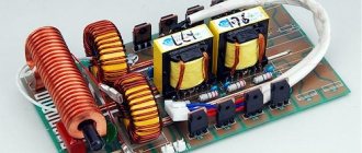
Photo - a powerful regulator for an asynchronous motor
The simplest example of a converter is a conventional voltage stabilizer. But the device under discussion has a much wider range of operation and power.
Frequency converters are used in any device that is powered by electrical energy. Governors provide extremely precise electrical motor control so that engine speed can be adjusted up or down, maintaining revs at the desired level, and protecting instruments from sudden revving. In this case, the electric motor uses only the energy needed to operate, instead of running it at full power.
Photo – DC motor speed controller
Why do you need a speed controller for an asynchronous electric motor:
- To save energy. By controlling the speed of the motor, the smoothness of its start and stop, strength and speed, you can achieve significant savings in personal funds. As an example, reducing speed by 20% can result in energy savings of 50%.
- The frequency converter can be used to control process temperature, pressure or without the use of a separate controller;
- No additional controller required for soft start;
- Maintenance costs are significantly reduced.
The device is often used for a welding machine (mainly for semi-automatic machines), an electric stove, a number of household appliances (vacuum cleaner, sewing machine, radio, washing machine), home heater, various ship models, etc.
Photo – PWM speed controller
Description of LUXEON EWR-5033 models
This phase indicator has many advantages. First of all, it is important to note that it has very convenient clamps. The model is well suited for working with power plants. The permissible humidity level of the device is 45%. The model's capacitors are of the pulse type.
Also, the advantages of the modification include a high-quality sensor. The generator in the phase indicator is used at 3 A. The model is also suitable for domestic use. However, it is important to note that it is quite expensive on the market. On average, the price of a phase indicator fluctuates around 8,300 rubles.
In any technology, LEDs are used to display operating modes. The reasons are obvious - low cost, ultra-low power consumption, high reliability. Since the indicator circuits are very simple, there is no need to purchase factory-made products.
From the abundance of circuits for making a voltage indicator on LEDs with your own hands, you can choose the most optimal option. The indicator can be assembled in a couple of minutes from the most common radioelements.
All such circuits are divided into voltage indicators and current indicators according to their intended purpose.
Let's consider the simplest option - phase checking.
This circuit is a current indicator light found on some screwdrivers. Such a device does not even require external power, since the potential difference between the phase wire and the air or hand is sufficient for the diode to glow.
To display the mains voltage, for example, to check the presence of current in the socket connector, the circuit is even simpler.
The simplest current indicator on 220V LEDs is assembled using capacitance to limit the current of the LED and a diode to protect against reverse half-wave.
Purpose of elements and principle of operation
Option for a car A simple circuit for indicating the voltage of the car's on-board network and battery charge. To increase sensitivity, a piece of insulated wire or a telescopic antenna can be used as an antenna. As an example, here is the simplest circuit on the ATMega controller
This option is suitable for circuits up to 12V. This indicator is suitable for testing wires and switches.
In addition to the display, such devices are equipped with a buzzer, which allows you to use the device without interference in conditions where the digital indicator is not visible. If a pulse voltage is applied to the probe input, the duty cycle of the pulses can be estimated by the brightness of a particular LED.
If the voltage is higher than the cutoff voltage of the field-effect transistor, it opens and pulls the gate of VT2 to ground, thereby closing it. And thanks to the constantly burning LED, it eats a lot.
Bolotnik and D.
Fine adjustment of the response threshold is set by resistor R2. The generator produces pulses with a duration of about 20 ms, followed by a frequency of 15 Hz.
Thus, despite its simplicity, the circuit allows you to know in advance that the battery has begun to run out. How to make a normal LED flasher from the circuit of a so-so working electric field indicator
Indicator for microcircuits (logic probe)
If there is a need to check the performance of a microcircuit, a simple probe with three stable states will help with this. If there is no signal (open circuit), the diodes do not light up. If there is a logical zero on the contact, a voltage of about 0.5 V appears, which opens transistor T1; if there is a logical one (about 2.4 V), transistor T2 opens.
This selectivity is achieved thanks to the different parameters of the transistors used. For KT315B the opening voltage is 0.4-0.5V, for KT203B it is 1V. If necessary, you can replace the transistors with others with similar parameters.
Controlling LEDs with Current Output Shift Registers
This article will focus on digital or alphanumeric displays for indicating various readings, which are often called indicators. Here we will focus on only one type of them - light-emitting diode (LED) seven-segment indicators and the nuances of handling them. In my opinion, one of the most ancient types of displays has been unfairly relegated to the periphery of development, although in many respects (contrast, readability, minimal unused window area, reliability and durability, finally) seven-segment LEDs give odds to any other varieties, including their closest competitors in the form OLED.
Their biggest obvious drawback is the limited number of available symbols. If you don’t get too sophisticated, then in fact these are only numbers and a small number of icons, like a minus, a degree or the letter E. To some extent, this drawback can be overcome if we take into account the 14- and 16-segment varieties. In addition, it can be bypassed almost completely if you remember about matrix LED indicators. But matrix indicators and their management are a subject for a separate discussion; here we will talk only about seven-segment ones. In a significant part of small projects at both the amateur and professional level - watches, weather sensors, various meters - only numbers and a minus sign are required to be displayed, so their capabilities are quite sufficient.
It’s strange, but there isn’t much literature about seven-segment LED indicators. The existing one is mainly divided into three parts - either these are ancient bulky dynamic display circuits based on counters and decoders, or educational examples of using Arduino with a single digit, or the use of ready-made modules (see below for the disadvantages and limitations of the latter). We will try to consider how to build a universal control unit for any such indicators on a more or less modern basis, without limiting ourselves to ready-made solutions.
Disadvantages of ready-made 7-segment modules
First, let's deal with ready-made modules. There are modules built either simply on a shift register like 74HC595 (which is not a very convenient option), or on special driver chips TM1637 (I2C interface) or MAX7219/MAX7221 (SPI interface). The convenience of using such drivers is that they organize dynamic display themselves, you don’t need to worry about it. That’s why such modules are popular in combination with Arduino - the connection diagram is extremely simple, and ready-made libraries will take care of the rest. The MAX7219/MAX7221 drivers also have a bunch of convenient options, which diversify the creation of a control program without complicating it too much. For some reason, the lion's share of such modules are produced in the “clock” configuration (with an additional colon in the middle), but it’s easy to purchase regular ones with decimal points and even eight-digit ones.
However, the disadvantage of ready-made modules on this basis is the very limited range of configurations of the indicators themselves. This is mainly due to the reluctance of manufacturers to stock up on different versions of the same device, which may never be in demand - for example, a combination of six standard sizes of indicators of different sign heights (within 0.3 - 0.8 inches) with six glow colors (red, green, yellow, amber, blue, white) gives 36 varieties to choose from, which, of course, no real seller can handle. Even on Ali you will find it good if there are three or four main colors and a couple of varieties in height, in the “bigger” and “smaller” options. In domestic online stores, the choice is even more limited.
And another small choice is due to the fact that the drivers are designed for 5-volt power supply, while large indicators (sign height 1 inch or more) require higher voltage control. Moreover, simply supplementing the above convenient microcircuit drivers with level converters is not easy - if you try to do this (which will require “increasing” the control of both bits and segments), then the circuit turns out to be too cumbersome, and the very use of these drivers degenerates, it is easier to use other solutions. If I'm not mistaken, no one dares to produce ready-made modules with large numbers.
If you want it done well, do it yourself
Next, I offer a universal solution for any standard sizes of indicators. Of course, this is not a ready-made module - you will have to tinker with manufacturing. But you are not limited by virtually anything, and you can choose indicators of the desired color and size with minimal changes in the circuit or without them at all. Difficulties will rather shift to the task of getting the right type of favorite color - the semiconductor crisis also affected this industry, and the offered range has sharply shrunk.
The circuit of the proposed solution does not contain current-setting resistors that clutter it up (which still need to be quite carefully selected for the supply voltage), and is as economical as possible in relation to other components. Moreover, the overall power supply of the circuit can be anything up to 16-17 volts without changes in the circuit, even unstabilized. The lower limit depends on the controller and indicators used, and we will talk about its selection later. Let us note right away that the solution is easily scalable for theoretically any number of digits (depending on the chosen option - see also below for this), and there are no fundamental problems in modifying it for matrix indicators.
But let's talk about everything in order.
LED driver MBI5167
All the solutions proposed below are based on a very convenient microcircuit - a driver for a line of 8 MBI5167 LEDs. A fairly sensible retelling of information from the datasheet can be found here. Purchasing MBI5167 is not a problem, but you can also find replacement analogs at the link provided. The microcircuit is available in two versions of a planar package (with a pitch of 1.27 and 0.64 mm), so for testing on a regular breadboard you will have to purchase an adapter with a pitch of 2.54.
MBI5167 is a combination of three functions in one device: a conventional 8-bit shift register, a latch register of its parallel outputs, and a line of separate current drivers to which LEDs are connected. In this case, the latch outputs are control signals for current drivers: if the corresponding position is one, the driver is on (the LED is on), if it is zero, it is off (the LED goes off). The supply voltage of the LED connected to the current output can be anything (up to 17 volts), as long as it exceeds the direct voltage drop across this LED.
Block diagram of MBI5167 current driver
The above is illustrated by the figure above, which is a copy of the block diagram from the datasheet with explanations translated into Russian. The driver outputs accept the incoming current, that is, they should be connected to the cathodes of the LEDs. So all further recommendations assume the use of indicators with a common anode.
MBI5167 pinout
The MBI5167 pinout is shown in the figure on the left. Before connecting, you must first decide what kind of current you want to set through the outputs. To set the current, use the pin designated R-EXT (pin 15 of the microcircuit). A resistor Rext (shown in the figure) is connected between this pin and ground. The current through each of the OUT pins is determined by the formula: Iout (mA) = 18.6/Rext (kOhm). That is, for a current of 5 mA, a resistor of 3.74 kOhm is needed, for 10 mA - 1.87 kOhm, for a current of 20 mA - 976 Ohms (the values closest to the calculated ones from the 1 percent series are given). Of course, it makes no sense to maintain the ratings with such accuracy (the error of the current sources themselves is ±3%), so 5% resistors of 3.6, 1.8 and 1 kOhm are quite suitable.
When drawing up a circuit, you will have to check the heat dissipation of the microcircuit, because excess voltage above the drop on the segment LED will drop at the current source, and this will cause the MBI5167 microcircuit to heat up. Let’s say right away that for average current values within 10 mA and LED supply voltages up to 15 volts, this is safe. In fact, let's roughly assume that the drop across the LED is 2 volts. Then, when the LED is powered at 15 volts, 13 volts will drop across each current source; at a current of 10 mA, this will lead to the release of 130 mW of heat. For seven segments this is almost exactly a watt, and the datasheet assures that the maximum heat dissipation value for the MBI5167 is about 1.5 watts. But, as you can see, these are almost the maximum values of the reserve base; exceeding them is undesirable. And if you want to increase the brightness, you will have to invent a lower voltage source.
Circuit and program for testing MBI5167
Connecting one digit to the MBI5167 chip
Connecting a register to a seven-segment indicator is shown in the figure above. The numbering of indicator pins here and in the diagrams below, of course, is omitted, since it can be very diverse - check the datasheet. The power supply to the microcircuit (pin Vcc) must match the power supply to the control microcontroller. It can be made from a general increased power supply using a low-power stabilizer, for example, type LP2950-5.0 or LP-2950-3.3. In the diagram, the power supply of the indicator anode is connected to a separate power supply U and, as we said, it can also be unstabilized.
To power indicators with one LED per segment (up to 0.8 inches inclusive) when using MBI5167, an unregulated power supply of 3-5 volts is sufficient, with two (1-1.5 inches) - 7-9 volts. The capabilities of the MBI5167 are sufficient for up to five or six LEDs per segment (three-inch indicators or more, direct drop - up to 12 volts, unstabilized power supply - about 15 volts). Well, probably, for street displays you need even larger indicators, but the solutions used there are clearly different.
Of course, for indicators of small sizes (up to 0.8 inches), you don’t have to isolate a separate power supply, simply connecting Ui to the same 5 volts, but then, on the contrary, this power supply must be well stabilized so that surges when switching segments do not affect the operation controller (the quality of the built-in Arduino stabilizer may not be enough!). And do not forget to check, in accordance with the selected current through the segment, whether the 100 mA stabilizer can withstand connecting 7-8 segments, or whether you will have to install something more powerful.
The codes for the seven-segment indicator are shown in the figure above. Note that in the diagram, segment a of the indicator is connected to the low-order bit of the register outputs (OUT0). Therefore, in the usual order of writing code from left to right from a to g (as in the table), it will have to be pushed through the register with the least significant bit first. The decimal point is in the least significant bit of the code (bit 0), but in the most significant output of the register (OUT7). That is, the codes of all digits will contain zeros in the least significant digit, and to illuminate the point, you just need to add one to the desired code when outputting.
The Arduino program for outputting one digit in one digit is called Shift_out_7seg_1dig. You will find it in the archive via the link at the end of the article. Arduino uses pins 10 (data - dataPin), 11 (overwriting - latchPin) and 12 (cycles - clockPin). Data output is carried out using the standard shiftOut() function.
Now let's move on to multi-digit indicators, which is much more interesting.
Static indication
You will be surprised, but to build the simplest static indication, and on indicators of any size, nothing else is required. Each seven-segment bit is connected by segment cathodes to a separate MBI5167 microcircuit. It is convenient to connect them into one long line by connecting the SDI input of the next digit to the SDO output of the previous one. Then, to control the entire line, three controller outputs are enough: to supply serial data to the first digit SDI input, to supply clock pulses (the CLK inputs of all microcircuits are combined) and to supply a rewrite pulse to the LE inputs (which are also combined with each other). Since the microcircuit is quite fast (the supply of clocks to the CLK input is up to 25 MHz, which is a couple of orders of magnitude higher than the frequency of, for example, the I2C bus), even taking into account the slow speed of the Arduino shiftOut() function, you will not experience any delays when updating data notice. The output speed using the shiftOut() function (of which there is no official information!) approximately corresponds to the actual output switching speed using digitalWrite() (see the discussion on this in my book, as well as in Monk's book). The clock frequency at the CLK pin is about 75 kHz, which means transferring a whole byte will take about 120 µs, taking into account the rewrite pulse at the LE pin.
Static indication 4 digits
This is illustrated by the diagram above, which shows the connection of four bits. If such a circuit is made for the specific purpose of indicating a temperature value within 99.9 degrees in absolute value, then it can be simplified by reducing the main part to three digits, and the degree icon (abfg segments) is permanently illuminated in the fourth digit using selected resistors. In any case, it doesn’t make sense to put a whole indicator for the minus sign (since it’s impossible to get a plus sign on seven-signal devices anyway) - it can be formed separately using a flat LED with a wavelength matched to the color of the indicator (don’t forget to paint the side edges of such an LED black marker). The same applies to the colon in the clock, which for blinking is simply powered from a separate pin of the controller (don't forget about color matching!).
The circuit will consume quite a lot of current. Usually we can assume that the necessary and sufficient current through one segment is 5 mA, then through four digits of seven segments each, in the extreme case (all eights), a total current of 5´7´4 = 140 mA will flow. At 10 mA per segment, it will already be 280 mA, not counting the decimal points. Which is not such a small value for low-power devices and it can create problems with heat dissipation inside the case. And while maintaining the selected brightness, it will not be possible to correct this by switching to dynamic display (see below for information on dynamic display).
The main disadvantage of this scheme is the large number of interconnections, which complicates and increases the cost of the board. With traditional static circuits controlled either from counters with decoders, or directly from the controller outputs, this drawback was decisive: in fact, to control 7 segments in 4 bits separately, 28 free controller outputs are needed. Replacing with a dynamic indication sharply reduces the number of control lines - for 4 digits only 11 of them are required (7 for segments and 4 for digits), so the dynamic option certainly won there. The shift register method reverses the situation with the control lines - as we will see, more is required for dynamic pin indication, although not too much in total. But in the static version, the individual connections of the MBI5167 registers to the cathodes of each of the indicators do not disappear, which still leaves the board quite bulky. And, most importantly, dual-triple-quad indicators (which can be cheaper and more compact than individual single-digit ones, and, in addition, dramatically simplify the board layout) cannot be used here; they are designed for a dynamic version.
Let me remind you that the link to the archive with test programs for Arduino is at the end of the article. The required static indication demo program is called Shift_out_7seg_4dig_static, the connection corresponds to the diagram above. The issue of the data source and its processing is ignored here; the program simply displays sequential numbers - first 1234, in the next cycle 5678.
Dynamic display and its features
Dynamic indication, first of all, allows you to reduce hardware costs: instead of a shift register (or a decoder with a latch in traditional circuits without a controller) installed for each bit separately, here you need one register for all bits. The number of connections on the board is also reduced - since all segments of the same name of different categories are combined, you can simply take double, triple or quad options, where the connections of the segments are already made inside a single case. We will not touch here on the above-mentioned case of using ready-made drivers such as MAX7219/MAX7221 or TM1637 - they, of course, allow you to reduce the number of required controller pins to a minimum (since they organize dynamic indication on their own), but, as we said, it is convenient to use them only within the 5-volt power supply of the indicators.
The price for the mentioned simplifications, firstly, is an increase in the number of control connections: now it is necessary not only to place the seven-segment code in the register, but also to power the required bit at the right time. For four digits, these are four additional lines. Usually, dynamic displays do not exceed 8 digits - if a larger number is needed, they simply install another similar module in parallel. The limitation here is connected not only with the control lines - as the number of digits increases, the fill factor (the relative glow time of each of the digits) decreases, which, in order to maintain brightness, forces the instantaneous current through the segment to increase, and this cannot be done indefinitely (see details below).
Connecting a bipolar transistor switch to control anodes
Secondly, to control the discharges you will need switches, in the general case (at an increased supply voltage of the indicators) - also equipped with level converters. In the simplest case, the keys (for indicators with a common anode, I remind you) can be PNP transistors connected to the power supply by the emitter. Level converters can be any low-power npn transistors, the collector circuit of which controls the inclusion of a pnp switch, and the base circuit is controlled by a controller. The corresponding diagram is shown in the figure.
The transistors in this circuit can be any, just take into account that the pnp switch controls the total current of all segments, and here, to achieve the same brightness, it can be several times higher than the optimal 5-10 mA per segment for the static version (see further section “ About the brightness of indicators"). In other words, for four bits, the pnp transistor VT2 must be selected with a permissible current of at least 0.5-0.6 A. The BC327 indicated in the diagram satisfies this condition, but if you have domestic ones lying around, you will have to install something from the average power - KT814/816 or even better, KT973. With small indicators and a 5 V power supply equal to the controller power supply, the level converter on the NPN transistor VT1 can be eliminated to simplify the circuit, but do not forget that the bit control logic must be inverted: the switched on bit will correspond to a logical zero at the controller output.
A circuit with bipolar transistors is the cheapest option, but not the best - firstly, the losses on the switches are high (both due to the voltage drop and due to their slow closing), and secondly, bipolar transistors require, as you can see from the diagram, corresponding resistors, so the circuit will be quite cumbersome.
I would like to note that for more than 20 years I have had a table clock with inch-high indicators successfully working, where the control keys for both digits and segments are made on Soviet bipolar transistors (which did not cost me anything at all then - as outdated, they were written off at some point). then the next inventory). Nothing happens to them, so the circuits are quite working. But I remember how I suffered, soldering a million MLT output resistors into the board, which, together with the transistors, took up half the board. Of course, if there are decoder drivers with current output, there is now no need to worry about segment control keys, and SMD components would take up three times less space, but why all this if there are more modern solutions?
MOSFETs are much more convenient as switches, especially in low-frequency circuits, where we can completely ignore dynamic losses. In addition, specifically for controlling these same MOSFETs, there is an immense assortment of standard level converters, the role of which is played by MOSFET drivers. And if we choose the field switch itself correctly (at the minimum threshold voltage VGS), then we can forget about any losses, regardless of the supply voltage.
Dynamic four-digit display
The corresponding diagram for four digits is shown in the figure. Dual TC4426A drivers with inverting output, convenient for p-channel transistors, are used as level converters. The IRFD9014 transistors shown in the diagram are produced in a “truncated DIP” (DIP-4) package, which is equally suitable for prototyping and installation on a board, where it does not take up too much space. Of course, you can choose from a million other options, including cheaper ones, but at low supply voltages, do not forget about the threshold voltage - VGS should be no more than 2-3 volts. As in the case of bipolar switches, with the same power supply to the controller and indicators, the TC4426A drivers can be eliminated (without forgetting to invert the bit control logic), but I would not recommend doing this: the circuit will work more reliably if everything is done strictly according to the instructions. Drivers do not load the controller outputs, and as an alternative to bipolar level converters, they simply take up less space on the board.
The demo program corresponding to this scheme is called Shift_out_7seg_4dig_dinam and it can also be found in the archive using the link at the end of the text. We also do not take into account the issue of the data source and its processing here; the program simply displays in each digit the figure corresponding to the digit number.
In the program, the bits are bypassed using the match interrupts of the 8-bit Timer 2. The timer is set to a frequency prescaler factor of 1024 (which gives 15625 Hz at the input), with the number 64 loaded into the match register, the interrupt frequency is equal to ~244 Hz. Each digit of a 4-digit number is lit for 1 period of this frequency, respectively, the refresh rate of each digit and the entire display is ~61 Hz. This is enough to prevent the eye from perceiving the flickering of the indicators. There is no need to significantly increase the switching frequency - we still need to receive data at some point and convert it into separate numbers, and also, possibly, perform all sorts of other actions. Dynamic display, carried out using separate driver chips, is about an order of magnitude faster (the MAX7219/MAX7221 have a bit scanning frequency of ~800 Hz), but they are busy only with this and are not distracted by anything else.
Please note that the power supply of the indicators, as already mentioned, may be unstabilized, but must be equipped with a good anti-aliasing filter - otherwise beats will inevitably occur between the power pulsation frequency and the bit switching frequency, as a result of which the brightness of the indicators will pulsate. The static indication method described above does not have this drawback: in it, a separate supply for the Ui discharges can even be an unsmoothed pulsating voltage directly from the bridge output.
About possible interruptions in dynamic display
Data preparation and conversion operations cannot interfere with dynamic display even in a slow Arduino, since language operators are still executed orders of magnitude faster (a few to tens of microseconds in the worst case) than updating the display bits (a few to tens of milliseconds). But the processes of receiving data through serial interfaces can slow down.
For example, the speed of a standard TWI (Wire library) is set by default at 100 Kbps, which gives an exchange speed of approximately 1 byte per 100 microseconds (taking into account all sorts of “starts” and “asks”), but in reality it is even less, since It takes some time to send device addresses and registers. We can assume that, for example, reading the complete contents of the DS1307 clock registers, consisting of 7 bytes (Seconds: Minutes: Hours: Day: Weekday: Month: Year) will take about 1 millisecond. This is comparable to the period of our discharge switching frequency (244 Hz - about ~4 ms), so you need to be quite careful about the correct organization of data exchange, which does not interfere with the indication. You won’t notice a single failure due to a delayed interrupt, but if the refresh period of the display bits starts to go off regularly, then a change or flickering in the brightness of the indicators will be noticeable to the eye. Moreover, increasing the exchange speed (the Wire library allows this) is not always possible: for example, the canonical DS1307 clock chip, as stated in its description, “operates in the regular mode (100kHz) only.”
Things are even worse with the UART interface. Fixed operating speeds from a predetermined range of values do not always allow the exchange to be organized without failures at a sufficiently high speed - the error in setting the bitrate turns out to be too large even at a 16 MHz controller frequency. That is why the preferred “default” speed in various projects is usually set to 9600 - this is a compromise value that works with sufficient reliability. But 9600 bps is ten times less than TWI, sending or receiving each byte takes about 1 millisecond. It is, of course, possible to increase it, but without subtle calculations and reservations it is still better to limit it to 38400, which does not fundamentally solve the problem. That is, when receiving data via UART, you have to think through the organization of exchange very carefully.
There are no problems with SPI speed; usually all devices easily support bitrates of 1 MHz and higher. But this interface is too rare among ordinary data sources: it is still, by nature, intended for board-wide exchange. Therefore, one way or another, the procedures for obtaining data have to be carefully timed.
About the brightness of indicators
The maximum permissible average current of one segment of indicators of conventional sizes (0.5-1.5 inches) approximately corresponds to the maximum current of signal LEDs, i.e. is about 30 mA. The usual value of the continuous glow current of a segment, at which any indicator will be clearly visible, is 5-10 mA (less for red ones, more for yellow and green). Moreover, to increase the visible contrast of a number, you should not stupidly increase the current through it - let us recall that drivers have their own limitations on the allocated power, and each type of indicator, in addition to the maximum permissible average current, also has a maximum dissipated power per segment, and what The further we stand from it, the more durable the scheme will be.
Therefore, the best way to improve the visibility of a number is to place the indicator under a smoky plexiglass filter, and at some distance deeper. The filter will make the background of the luminous segment, even with the usual milky-matte front surface of the case, visually completely black, and the overall contrast will increase, despite the fact that the filter itself will retain part of the emitted light. This is especially important when viewing the display from afar, for example, in a table clock or wall-mounted weather station. Note that a neutral gray smoky filter is the most universal, but if you have indicators of the same color, then you can choose a filter of the appropriate shade: for example, yellow indicators look better through brown plexiglass (but green indicators may lose color saturation). Instead of smoky or colored transparent plexiglass, which can be difficult to obtain, you can use filter films used in photography and theater.
Another nuance that should be taken into account is that the decimal point of larger-sized indicators usually differs from other segments by a reduced forward voltage drop (for example, for 1-inch-high indicators, the segment consists of two LEDs connected in series, and the decimal point of one). Therefore, if you want to illuminate the decimal point separately from the numbers through a resistor so that it does not stand out against the background of the numbers or does not shine too dimly, the value of this resistor will have to be adjusted individually - most likely, it will not be possible to calculate its exact value.
When the decimal point is connected to a driver with a current output, this circumstance ceases to matter, but an annoying error appears, which, it seems, absolutely all seven-segment manufacturers make. The round dot visually appears smaller than the other segments (having the shape of an elongated parallelogram or rectangle) and, with the same brightness, is lost against their background - from a distance you won’t understand where exactly the separator is. Therefore, it is not at all harmful to illuminate it separately and adjust the brightness so that the decimal point stands out a little. This problem is completely absent in varieties with a semicolon instead of a period, or in those rare cases where the period is not round but rectangular. Let us note in parentheses that in some LCD displays this problem is even more acute and it is not possible to somehow smooth it out at all. Well, display development companies have no idea about the need to attract type designers (and if only this were their only omission in terms of design!).
With dynamic display, a duty cycle is superimposed on all this. In our case, it is equal to the inverse of the number of indicators (in drivers like TM1637 and MAX7219/MAX7221 this is not the case!). The dependence of visible brightness on the fill factor is generally nonlinear, but we can assume that, within practically significant limits, it is inversely proportional to the number of indicators. Therefore, with two indicators, the current selected in static mode through the segment should be doubled, and with four indicators, it should be quadrupled. It is easy to calculate that already with 4 small indicators, if the initially selected current value is 10 mA, we seem to go beyond the maximum permissible current of 30 mA. But everything will fall into place if we remember that this is the maximum permissible average current, and the average value does not change depending on the duty cycle. But the peak current, of course, is limited, therefore, if there are a large number of indicators, it will be better for them if you divide the indicators into groups of no more than 4-5 pieces in each.
Brightness control
Drivers have special brightness control commands that regulate the relative duration of the discharge on state. The TM1637 has 8 brightness levels, the MAX7219/MAX7221 has 16 each. In reality, this number of steps is completely unnecessary - usually three values are important (low-medium-high), but these values themselves for different types of displays may differ, and also depend on the density of filters installed, as we said, to increase contrast.
In practice, in our case, the presence of initial software adjustment is not necessary: it is easier to pre-select the current value for specific conditions using the current-setting resistor Rext. The only time such adjustment is needed is the need to adjust the brightness depending on the external lighting. In some cases, this is an absolutely mandatory function (displays on the dashboard of a car, on ship control panels - in order to avoid illumination of the field of view and reflections in windshields at night), and you just often want to dim the brightness of the table clock at night.
In the case of static indication, pure software adjustment cannot be achieved; you will have to switch the Rext current-setting resistors in all categories simultaneously. This isn't very difficult to do with CMOS switches (like the 74HC4066, the vintage 590KH2, or low-power electronic relays), it just clutters up the circuit quite a bit.
Here the dynamic display wins - there are no problems with software adjustment. To implement this, it is enough to introduce a delay in each period to turn on the discharge within the duration of the period. There is no need to describe it in detail - practical cases can be very different, from manual installation with the “more or less” button to automatic smooth or step adjustment depending on the illumination measured by a photodiode. I note that in the case of manual adjustment, it’s a good idea to store the set brightness in the EEPROM so that you don’t have to press the button after every power outage.
And here is the promised link to the archive with the programs ( UPD : the dynamic display program has been corrected according to the fair comments of Serge78rus). I did not post assembler demo versions; anyone who needs low-level control (it is much more flexible and convenient) - please contact me.