DIY voltage converter 12-220 (simple circuit)
The initial goal for the project was to make a powerful 12 to 220 converter. The main advantage of this device is its ease of assembly, made using a push-pull circuit. Only 2 field-effect transistors, without any master oscillators. Even if you have experience in such a matter as assembling a converter, but there is a great desire to try, then there is nothing difficult about it, you can easily assemble it with your own hands.
It is not necessary to buy any parts for the device; all components can be found at home in old equipment.
Let's watch a video of the converter:
As for the converter parameters, unfortunately, the output frequency is variable, but you can easily turn it into direct current by installing a rectifier and a large capacitor at the output with a calculated capacitance of about 100 microfarats, at a voltage of 400 volts. The operating frequency depends on the LC circuit. We use the primary winding of the coil as a coil. 2 throttles installed. The winding has no tap.
As for the circuit, it will allow you to remove up to 500 watts or half a kilowatt of output power, without any master circuits or other structures.
On the generator board itself, in addition to the transistor, zener diodes are also installed to stabilize the gate voltage. There is also a 470 ohm shutter stop; for the design, anything from 100 to 670 ohms can be used.
In addition, 2 diodes are installed.
When using one common heat sink, they must be insulated with gaskets and insulating washers.
If the inductor overheats a little, you need to wrap it with a wire with a diameter of up to 2 mm.
The transformer used a ready-made 220 volt with a primary winding. The winding consists of 8 turns of thick wire.
The diagram can be without a midpoint or with a midpoint.
In our case, an 11-watt incandescent lamp is connected. We need to illuminate it with full heat.
All of the above devices can be powered from direct current. You cannot power a refrigerator, vacuum cleaner, or microwave. You can power the charger from your phone, laptop, or even your computer.
Electrical circuit of the inverter
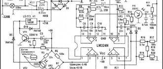
An integrated controlled multivibrator CD4047BD with elements for adjusting the repetition rate of generated pulses is used as a key component of the device; the power part is assembled on paired field-effect transistors. To obtain an output voltage of 220 V, a step-up transformer is used, the inputs of the primary windings of which are connected directly to the terminals D (drains) of the power transistor assemblies.
Power final stages A are assembled on paired field-effect transistors. The final stage circuit is shown below.
200-ohm resistors in the gate circuit ensure equalization of currents across individual transistors.
How to make inverters (converters) 12-220 V
To connect household devices to the car’s on-board electrical system, you need an inverter that can increase the voltage from 12 V to 220 V. There are sufficient quantities of them on store shelves, but their price is not encouraging. For those who are a little familiar with electrical engineering, it is possible to assemble a 12-220 volt voltage converter with your own hands. We will analyze two simple schemes.
Converters and their types
There are three types of 12-220 V converters. The first is from 12 V to 220 V. Such inverters are popular among motorists: through them you can connect standard devices - TVs, vacuum cleaners, etc. Reverse conversion - from 220 V to 12 - is required infrequently, usually in rooms with severe operating conditions (high humidity) to ensure electrical safety. For example, in steam rooms, swimming pools or baths. In order not to take risks, the standard voltage of 220 V is reduced to 12, using appropriate equipment.
Voltage converters are available in sufficient quantities in stores.
The third option is, rather, a stabilizer based on two converters. First, the standard 220 V is converted to 12 V, then back to 220 V. This double conversion allows you to have an ideal sine wave at the output. Such devices are necessary for the normal operation of most electronically controlled household appliances. In any case, when installing a gas boiler, it is strongly recommended to power it through just such a converter - its electronics are very sensitive to the quality of power, and replacing the control board costs about half the boiler.
Pulse converter 12-220V 300 W
This circuit is simple, the parts are available, most of them can be removed from a computer power supply or purchased at any radio store. The advantage of the circuit is its ease of implementation, the disadvantage is the non-ideal sine wave at the output and the frequency is higher than the standard 50 Hz. That is, devices that require power supply cannot be connected to this converter. You can directly connect not particularly sensitive devices to the output - incandescent lamps, iron, soldering iron, phone charger, etc.
The presented circuit in normal mode produces 1.5 A or pulls a load of 300 W, at a maximum of 2.5 A, but in this mode the transistors will noticeably heat up.
Voltage converter 12-220 V: converter circuit based on a PWM controller
The circuit was built on the popular TLT494 PWM controller. Field-effect transistors Q1 Q2 should be placed on radiators, preferably separate ones. When installing on one radiator, place an insulating gasket under the transistors. Instead of the IRFZ244 indicated in the diagram, you can use IRFZ46 or RFZ48, which are similar in characteristics.
The frequency in this 12 V to 220 V converter is set by resistor R1 and capacitor C2. The values may differ slightly from those shown in the diagram. If you have an old non-working power supply for your computer, and it contains a working output transformer, you can put it in the circuit. If the transformer is not working, remove the ferrite ring from it and wind the windings with copper wire with a diameter of 0.6 mm. First, the primary winding is wound - 10 turns with the output from the middle, then, on top - 80 turns of the secondary.
As already said, such a 12-220 V voltage converter can only work with a load that is insensitive to power quality. To be able to connect more demanding devices, a rectifier is installed at the output, the output voltage of which is close to normal (diagram below).
A rectifier is added to improve output characteristics
The circuit shows high-frequency diodes of the HER307 type, but they can be replaced with the FR207 or FR107 series. It is advisable to select containers of the specified size.
Inverter on a chip
This 12-220 V voltage converter is assembled on the basis of a specialized KR1211EU1 microcircuit. This is a generator of pulses that are removed from outputs 6 and 4. The pulses are antiphase, with a short time interval between them to prevent the simultaneous opening of both keys. The microcircuit is powered by a voltage of 9.5 V, which is set by a parametric stabilizer on a D814V zener diode.
Also in the circuit there are two high-power field-effect transistors - IRL2505 (VT1 and VT2). They have a very low open resistance of the output channel - about 0.008 Ohms, which is comparable to the resistance of a mechanical key. Permissible direct current is up to 104 A, pulsed current is up to 360 A. Such characteristics actually make it possible to obtain 220 V with a load of up to 400 W. Transistors must be installed on radiators (with a power of up to 200 W it is possible without them).
12-220 V boost converter circuit
The pulse frequency depends on the parameters of resistor R1 and capacitor C1; capacitor C6 is installed at the output to suppress high-frequency surges.
It is better to take a ready-made transformer. In the circuit, it is turned on in reverse - the low-voltage secondary winding serves as the primary, and the voltage is removed from the high-voltage secondary.
Possible replacements in the element base:
- The D814V zener diode indicated in the circuit can be replaced with any one that produces 8-10 V. For example, KS 182, KS 191, KS 210.
- If there are no capacitors C4 and C5 of type K50-35 at 1000 μF, you can take four 5000 μF or 4700 μF and connect them in parallel,
- Instead of an imported capacitor C3 220m, you can supply a domestic one of any type with a capacity of 100-500 µF and a voltage of at least 10 V.
- Transformer - any with a power from 10 W to 1000 W, but its power must be at least twice the planned load.
When installing circuits for connecting a transformer, transistors and connecting to a 12 V source, it is necessary to use large cross-section wires - the current here can reach high values (with a power of 400 W up to 40 A).
Inverter with pure sine wave output
The circuits of daytime converters are complex even for experienced radio amateurs, so making them yourself is not at all easy. An example of the simplest circuit is below.
Inverter circuit 12 200 with pure sine output
In this case, it is easier to assemble such a converter from ready-made boards. How - watch the video. The next video shows how to assemble a 220 volt converter with pure sine wave. Only the input voltage is not 12 V, but 24 V. And this video explains how you can change the input voltage, but still get the required 220 V at the output.
Inverter with pure sine wave output
The circuits of daytime converters are complex even for experienced radio amateurs, so making them yourself is not at all easy. An example of the simplest circuit is below.
Inverter circuit 12 200 with pure sine output
In this case, it is easier to assemble such a converter from ready-made boards. How - watch the video.
The next video shows how to assemble a 220 volt converter with pure sine wave. Only the input voltage is not 12 V, but 24 V. And this video explains how you can change the input voltage, but still get the required 220 V at the output.
Source
Voltage converter 12 220 circuit
The device is built on a push-pull inverter with two powerful field-effect transistors. Any N-channel field-effect transistors with a current of 40 Amps or more are suitable for this design, I used inexpensive IRFZ44/46/48 transistors, but if you need more power at the output, it is better to use more powerful field-effect transistors IRF3205.
We wind the transformer on a ferrite ring or an E50 armored core, or you can use any other one. The primary winding should be wound with a two-core wire with a cross-section of 0.8 mm - 15 turns. If you use an armored core with two sections on the frame, the primary winding is wound in one of the sections, and the secondary winding consists of 110-120 turns of copper wire 0.3-0.4 mm. At the output of the transformer we obtain an alternating voltage in the range of 190-260 Volts, rectangular pulses.
The 12 220 voltage converter whose circuit has been described can power various loads, the power of which is no more than 100 watts
Output pulse shape - Rectangular
A transformer in a circuit with two primary windings of 7 Volts (each arm) and a mains winding of 220 Volts. Almost any transformers from uninterruptible power supplies are suitable, but with a power of 300 watts or more. The diameter of the primary winding wire is 2.5 mm.
Transistors IRFZ44, if missing, can be easily replaced with IRFZ40,46,48 and even more powerful ones - IRF3205, IRL3705. The transistors in the TIP41 (KT819) multivibrator circuit can be replaced with domestic KT805, KT815, KT817, etc.
Attention, the circuit does not have protection at the output and input from short circuit or overload, the keys will overheat or burn out.
Two versions of the printed circuit board design and a photo of the finished converter can be downloaded from the link above.
This converter is quite powerful and can be used to power a soldering iron, grinder, microwave oven and other devices. But do not forget that its operating frequency is not 50 Hertz.
The primary winding of the transformer is wound with 7 cores at once, with a wire with a diameter of 0.6 mm and contains 10 turns with a tap from the middle stretched across the entire ferrite ring. After winding, we insulate the winding and begin to wind the step-up winding, with the same wire, but already 80 turns.
It is advisable to install power transistors on heat sinks. If you assemble the converter circuit correctly, it should work immediately and does not require any configuration.
As with the previous design, the heart of the circuit is the TL494.
This is a ready-made push-pull pulse converter device; its complete domestic analogue is 1114EU4. High-efficiency rectifier diodes and a C-filter are used at the output of the circuit.
In the converter I used a ferrite W-shaped core from the TPI TV transformer. All the original windings were unwound, because I re-wound the secondary winding 84 turns with 0.6 wire in enamel insulation, then a layer of insulation and move on to the primary winding: 4 turns oblique from 8 0.6 wires, after winding the windings were ringed and divided in half, we got 2 windings of 4 turns in 4 wires, the beginning of one was connected to the end of the other, so we made a tap from the middle, and finally wound the feedback winding with five turns of PEL 0.3 wire.
The 12 220 voltage converter circuit that we examined includes a choke. You can make it yourself by winding it on a ferrite ring from a computer power supply with a diameter of 10 mm and 20 turns of PEL 2 wire.
There is also a drawing of a printed circuit board for a 12,220 volt voltage converter circuit:
And a few photos of the resulting 12-220 Volt converter:
Again, I liked the TL494 paired with mosfets (This is such a modern type of field-effect transistors), this time I borrowed the transformer from an old computer power supply. When laying out the board, I took into account its conclusions, so be careful when choosing your placement option.
To make the case, I used a 0.25L soda can, which I had successfully snatched up after a flight from Vladivostok, cut off the top ring with a sharp knife and cut out the middle of it, and glued a circle of fiberglass with holes for a switch and connector into it using epoxy.
To give the jar rigidity, I cut a strip the width of our body from a plastic bottle, coated it with epoxy glue and placed it in the jar. After the glue had dried, the jar became quite rigid and had insulated walls; the bottom of the jar was left clean for better thermal contact with the radiator of the transistors.
To complete the assembly, I soldered the wires to the cover and secured it with hot glue; this will allow, if the need arises, to disassemble the voltage converter by simply heating the cover with a hairdryer.
The design of the converter is designed to convert 12 volt voltage from the battery into 220 volt alternating voltage with a frequency of 50 Hz. The idea for the circuit was borrowed from an old issue of radio magazine from November 1989.
The amateur radio design contains a master oscillator designed for a frequency of 100 Hz on the K561TM2 trigger, a frequency divider by 2 on the same chip, but on the second trigger, and a power amplifier using transistors loaded by a transformer.
Taking into account the output power of the voltage converter, transistors should be installed on radiators with a large cooling area.
The transformer can be rewound from an old network transformer TS-180. The mains winding can be used as a secondary winding, and then windings Ia and Ib are wound.
A voltage converter assembled from working components does not require adjustment, with the exception of the selection of capacitor C7 with a connected load.
If you need a printed circuit board drawing made in the sprint layout program, click on the PCB drawing.
Signals from the PIC16F628A microcontroller through 470 Ohm resistances control the power transistors, forcing them to open one by one. The half-windings of a transformer with a power of 500-1000 VA are connected to the source circuits of field-effect transistors. There should be 10 volts on its secondary windings. If we take a wire with a cross-section of 3 mm2, then the output power will be about 500 W.
The whole design is very compact, so you can use a breadboard without etching the tracks. You can catch the archive with the microcontroller firmware at the green link just above
The 12-220 converter circuit is made on a generator that creates symmetrical pulses that follow out of phase and an output block implemented on field switches, the load of which is connected to a step-up transformer. Using elements DD1.1 and DD1.2, a multivibrator is assembled according to the classical scheme, generating pulses with a repetition frequency of 100 Hz.
To form symmetrical pulses traveling in antiphase, the circuit uses a D-trigger of the CD4013 microcircuit. It divides by two all impulses entering its input. If we have a signal going to the input with a frequency of 100 Hz, then the output of the trigger will be only 50 Hz.
Since field-effect transistors have an insulated gate, the active resistance between their channel and the gate tends to an infinitely large value. To protect the trigger outputs from overload, the circuit has two buffer elements DD1.3 and DD1.4, through which the pulses travel to the field-effect transistors.
A step-up transformer is included in the drain circuits of the transistors. To protect against self-induction, high-power zener diodes are connected to the drains. RF interference suppression is carried out by a filter on R4, C3.
The winding of the inductor L1 is made by hand on a ferrite ring with a diameter of 28 mm. It is wound with PEL-2 0.6 mm wire in one layer. The most common network transformer is 220 volts, but with a power of at least 100 W and having two secondary windings of 9 V each.
To increase the efficiency of the voltage converter and prevent severe overheating, field-effect transistors with low resistance are used in the output stage of the inverter circuit.
On DD1.1 – DD1.3, C1, R1, a rectangular pulse generator with a pulse repetition rate of 200 Hz is made. Then the pulses arrive at a frequency divider built on elements DD2.1 - DD2.2. Therefore, at the output of the divider 6, the output of DD2.1, the frequency is reduced to 100Hz, and already at the 8th output of DD2.2. it is 50 Hz.
The signal from pin 8 of DD1 and pin 6 of DD2 goes to diodes VD1 and VD2. To fully open the field-effect transistors, it is necessary to increase the amplitude of the signal that passes from the diodes VD1 and VD2; for this, bipolar transistors VT1 and VT2 are used in the voltage converter circuit. The field-effect output transistors are controlled through VT3 and VT4. If no errors were made during the assembly of the inverter, then it starts working immediately after power is applied. The only thing that is recommended to do is to select the value of resistance R1 so that the output is the usual 50 Hz.
The transformer for the voltage converter circuit 12 220 can be made with your own hands. To do this, you will have to slightly remake the old power transformer from a domestic TV. We remove all windings, except the network one. Then we wind two windings with PEL wire - 2.1 mm. Field-effect transistors must be installed on the radiator.
In this converter circuit, the generator generates rectangular pulses with a repetition frequency of about 50 Hz with protective pauses that prevent the simultaneous opening of field-effect transistors VT5 and VT6. When output Q1 (or Q2) goes low, transistors VT1 and VT3 (or VT2 and VT4) open, and the gate capacitances begin to discharge, and transistors VT5 and VT6 close. The converter itself is assembled according to the classic push-pull circuit. If the voltage at the output of the converter exceeds the set value, the voltage at resistor R12 will be higher than 2.5 V, and therefore the current through the DA3 stabilizer will increase sharply and a high-level signal will appear at the FV input of the DA1 chip.
Its outputs Q1 and Q2 will switch to the zero state and field-effect transistors VT5 and VT6 will close, causing a decrease in the output voltage. A current protection unit based on relay K1 has also been added to the voltage converter circuit. If the current flowing through the winding is higher than the set value, the contacts of the reed switch K1.1 will operate. The FC input of the DA1 chip will be high and its outputs will go low, causing transistors VT5 and VT6 to close and a sharp decrease in current consumption.
After this, DA1 will remain in a locked state. To start the converter, a voltage drop at the input IN DA1 will be required, which can be achieved either by turning off the power or by short-circuiting capacitance C1. To do this, you can introduce a non-latching button into the circuit, the contacts of which are soldered parallel to the capacitor. Since the output voltage is a square wave, capacitor C8 is designed to smooth it out. The HL1 LED is necessary to indicate the presence of output voltage. The T1 transformer is made from TS-180; it can be found in the power supplies of old CRT televisions. All its secondary windings are removed, and the network voltage of 220 V is left. It serves as the output winding of the converter. Half-windings 1.1 and I.2 are made from PEV-2 wire 1.8, 35 turns each. The beginning of one winding is connected to the end of the other. The relay is homemade. Its winding consists of 1-2 turns of insulated wire, designed for a current of up to 20.30 A. The wire is wound on the reed switch body with making contacts.
By selecting resistor R3, you can set the required frequency of the output voltage, and resistor R12 - the amplitude from 215 to 220 V.
Half-bridge power module
Now it's time to take a closer look at today's hero.
The module is universal and allows you to work with Mosfet and IGBT transistors, both low-voltage and high-voltage switches up to 1200V. Module features:
- Galvanic isolation of the control (digital) side from the power side. Insulation breakdown voltage 3 kV;
- The upper and lower switches are independent, each has its own galvanically isolated driver and galvanically isolated dc/dc;
- A modern driver from Infineon is used - 1EDC60I12AHXUMA1. Opening/closing pulse current - 6A/10A. Maximum frequency - 1 MHz (tested up to 1.5 MHz stable);
- Hardware current protection: shunt + op-amp + comparator + optocoupler;
- Maximum current - 20A. It is limited not by the keys, but by the size of the radiator and the thickness of the copper polygons.
The article mentions the 1st revision of the module, it is fully working, but there will be a 2nd revision, in which purely design flaws will be eliminated and the connectors will be changed to more convenient ones. After completing the creation of the documentation, I dropped the gerber into PCBway and 6 days later the courier knocked on my door and handed me this beauty:
Another week later, the dogs finally brought the components from an excellent domestic store. In the end everything was installed:
Before moving further, let's look at the circuit diagram of the module. You can download it here - PDF.
There is nothing complicated or magical here. Regular half-bridge: 2 keys at the bottom, 2 at the top, you can solder one at a time. The driver, as written above, is from the 1ED family, very evil and immortal. There is an indication of the power supply everywhere, including +12V at the dc/dc output. The protection is implemented on the AND logic element; if the current exceeds, the comparator will output +3.3V, they will light up the optocoupler and it will pull one of the AND inputs to ground, which means that log.0 will be established and the PWM signal from the drivers will disappear. AND with 3 inputs was used specifically; in the next revision I plan to also add protection against overheating by the radiator and send an error signal there. All sources will be at the end of the article.
DIY voltage converter 12 220 simple circuit 500 watts
This version of the voltage converter can be used for independent repetition. The main advantage is reliable operation, simplicity and, of course, power. Many who see the diagram will probably not believe that such a simple inverter can deliver such power, but in fact it is. Speaking of power, during the tests it was possible to obtain a modest 200 watts from a 12 Volt source, but of course this is not the limit, the inverter can also operate from a voltage of 24 volts, without any replacements in the circuit, in this case the output power is pure will be around 300 watts, but this is not the limit - the power can be increased to 500 watts! And these are very real indicators.
Converter circuit 12-220
The circuit is quite often found on the Internet, I noticed errors on some resources, so once again I will provide a fully WORKING version of the converter. The inverter works exactly like any other push-pull converter. It does not contain additional frequency generators; the power element in the circuit is powerful N-channel field switches operating on the multivibrator principle.
Working at a certain frequency, a high-frequency alternating voltage is generated in the primary winding of a pulse transformer, and then everything follows according to the induction method.
The keys overheat during operation, since the efficiency of the circuit is not at a high level (no more than 65%), therefore, the keys must be installed on heat sinks, and do not forget about the mica gaskets.
You can not wind the transformer, but take a ready-made one from a computer power supply, and ANY transformers from any power supply will do, regardless of the brand and date of manufacture of the unit.
Video of converter operation
The zener diodes in the circuit are preferably 1 watt with a stabilization voltage of 12-15 Volts; they are needed to stabilize the voltage on the gates of the switches, otherwise there is a danger of overvoltage, and as we know, field-effect transistors are controlled by voltage and increasing the permissible voltage at the gate can lead to failure transistor. Diodes - any fast and ultra-fast diodes with a current of 1 Ampere or more; you can use UF4007, HER107, HER207, HER307, MUR460, BYV26, etc. from the available diodes. I will not provide calculations for the transformer, since the best option is to use a ready-made transformer from a computer power supply.
Universal converter type
In order to make a step-up voltage converter with your own hands combined with a step-down voltage converter with your own hands, you will need to make some improvements and elements such as:
- high-voltage converter device up to 400 kiloVolt;
- module for enhancement;
- low-voltage conversion device 5Volt to 1.5Amp;
- 500W boost converter;
- voltage regulation kit.
The compact device produces high power with a single-cycle operating mode. Typically, such standard devices are capable of performing only one function. Increase or raise the voltage. A universal proprietary solution can combine these two features.
To test self-made devices, a variety of power supplies are used. The devices can be charged and used for various tasks.
DIY voltage converter 12 220 simple circuit 500 watts
Download the board in lay format. The board without parts is shown only as traces.
About diodes: any, put CD 103, CD 521, any low-power pulsed ones. The circuit is not critical to details. Everything that came to hand was installed. Output power transistors, depending on the required power and the transformer used, from KT 805. KT 827 (KT 817 + KT 819), germanium P210 to powerful field-effect transistors. Sometimes the circuit was turned to a different polarity, forced by the lack of details. The output was set to CT 825, and the build-up CT was set to 972 (but in such a circuit it was necessary to fine-tune the base currents, select the transistors themselves, which is very unstable). Usually the circuit operated at a frequency of 50 hertz, although reconfigurations are allowed, I did it at 4 kHz (change the frequency by selecting capacitors in the circuit of the microcircuit and using a transformer with ferrite cores).
Transformer is a different story. Mainly I rewound television TS250, TS270, TS280 and the like with two reels, they are easy to disassemble. I wound up all the windings, leaving only the network one, while winding up I determined the number of turns per volt and wound it with a wire 1 - 2 mm in diameter, depending on the power (for vehicles with 280 and 200 watts of power I took copper no thinner than 1.5) to obtain a voltage of approximately 10.5 -11.5 volt. Sometimes I used ready-made transformers from decommissioned military equipment TN-61, TN-48, one with a power of 180 watts, the second up to 100, sometimes I paralleled them in 2 pieces for greater output power. The output voltage of these transformers is 4x6 volts, with additional control taps on both the primary and secondary windings. I connected the secondary (for the converter they will become part of the primary winding) in parallel - 2x2 in series to obtain one winding with a tap from the middle, control pins on the primary (for the converter this is the secondary, output winding) I achieved a higher voltage, so with a 12x220 layout the output will always be 200 -210 volts (for this reason I always wound up the transformers at 10.5 - 11 volts).
In principle, if the output voltage is not critical (it was critical for powering tube TVs; at lower voltages, the sensitivity of the radio path and image contrast decreased), then you can use 9-13 volt windings in any transformers (the lower the voltage the trans was designed for, the more get a higher one at the output of the converter), the winding must withstand a current of 8-12 amperes and higher.
Options: Global
A 12-220 V voltage converter to power a load up to 1000 W or more can generally be made independently in the following ways (in order of increasing costs):
- Place a ready-made unit in a case with a heat sink from Avito, Ebay or AliExpress. Search for "inverter 220" or "inverter 12/220"; you can immediately add the required power. It will cost approx. half the price of the same factory one. No electrical skills required, but - see below;
- Assemble the same one from the kit: printed circuit board + “scattered” components. It can be purchased there, but diy is added to the request, which means self-assembly. Price still approx. 1.5 times lower. Basic skills in radio electronics are required: the ability to solder, use a multimeter, knowledge of the wiring (pinouts) of the terminals of active elements or the ability to look for them, the rules for including polar components (diodes, electrolytic capacitors) in the circuit and the ability to determine what current and what cross-section wires are needed;
- Adapt a computer uninterruptible power supply (UPS, UPS) to the inverter. A working used UPS without a standard battery can be found for 300-500 rubles. You don’t need any skills - you simply connect the car battery to the UPS. But you will have to charge it separately, also see below;
- Choose a conversion method, a diagram (see below) in accordance with your needs and the availability of parts, calculate and assemble completely yourself. It may be completely free, but in addition to basic electronic skills, you will need the ability to use some special measuring instruments (also see below) and perform simple engineering calculations.
From a finished module
Assembly methods according to paragraphs. 1 and 2 are actually not that simple. The housings of ready-made factory inverters also serve as heat sinks for powerful transistor switches inside. If you take a “semi-finished product” or “loose”, then there will be no housing for them: given the current cost of electronics, manual labor and non-ferrous metals, the difference in prices is explained precisely by the absence of the second and, possibly, the third. That is, you will have to make a radiator for powerful keys yourself or look for a ready-made aluminum one. Its thickness at the location where the keys are installed should be at least 4 mm, and the area for each key should be at least 50 square meters. see for each kW of power output; with blowing from a 12 V computer fan-cooler 110-130 mA – from 30 sq. cm*kW*key.
Ready-made 12/220 V voltage inverter modules
For example, there are 2 keys in a set (module) (they can be seen, they stick out from the board, see on the left in the figure); modules with keys on the radiator (on the right in the figure) are more expensive and are designed for a certain, usually not very high power. There is no cooler, the power required is 1.5 kW. This means you need a radiator of 150 sq. see. In addition to this, there are also installation kits for keys: insulating heat-conducting gaskets and fittings for mounting screws - insulating cups and washers. If the module has thermal protection (there will be some other piece sticking out between the keys - a thermal sensor), then a little thermal paste to glue it to the radiator. Wires - of course, see below.
From UPS
The 12V DC/220V AC 50Hz inverter, to which you can connect any devices within the permissible power limit, is made from a computer UPS quite simply: the standard wires to “your” battery are replaced with long ones with clamps for the car battery terminals. The wire cross-section is calculated based on the permissible current density of 20-25 A/sq. mm, see also below. But because of a non-standard battery, problems can arise - with it, and it is more expensive and more necessary than a converter.
UPS also uses lead-acid batteries. This is today the only widely available secondary chemical power source capable of regularly delivering large currents (extra currents) without being completely “killed” in 10-15 charge-discharge cycles. In aviation, silver-zinc batteries are used, which are even more powerful, but they are monstrously expensive, are not widely available, and their service life is negligible by everyday standards - approx. 150 cycles.
The discharge of acid batteries is clearly monitored by the voltage on the bank, and the UPS controller will not allow the “foreign” battery to be discharged beyond measure. But in standard UPS batteries the electrolyte is gel, while in car batteries it is liquid. The charging modes in both cases are significantly different: the same currents cannot be passed through the gel as through a liquid, and in a liquid electrolyte, if the charge current is too low, the mobility of the ions will be low and not all of them will return to their places in the electrodes. As a result, the UPS will chronically undercharge the car battery; it will soon become sulfated and become completely unusable. Therefore, a battery charger is required for the inverter on the UPS. You can make it yourself, but that's another topic.
Simple inverter 12V - 220V 50Hz
What distinguishes this converter is that it provides a full sinusoidal voltage with a frequency of 50 Hz. The inverter converts 12 V DC to 220 V AC, frequency 50 Hz. It has a minimum number of components and small size. The power of the inverter is determined by the power of its transformer and in my case it lies in the range of 30-50 W. The output voltage has a sinusoidal waveform. You can power lamps, laptops, charge cell phones, electric razors, etc. from the inverter. Since the inverter frequency is 50 Hz, you can connect any devices with a power consumption of up to 30 W. List of components:
Converter circuit
The microcircuit contains a multivibrator that generates rectangular pulses with a frequency of 50 Hz. Transistor Q1 is inverting, as a result, the output stages on transistors Q2 and Q3 operate alternately. This circuit is called push-pull. The load of the output stages is a step-up transformer, which converts the voltage to 220 V and generates a sinusoidal signal from rectangular pulses.
Inverter assembly
The inverter is assembled on a breadboard. The elements are inserted and sealed at the bottom with jumpers. The transistors of the output stages are installed on small heat sinks. With proper assembly and serviceable components, the converter begins to work immediately and does not require adjustment. The circuit is simple, does not contain complex electronics and has proven itself well. The inverter works well from a car battery. As a matter of fact, I made this inverter for the car. Video:
sdelaysam-svoimirukami.ru
Battery and power
The suitability of the converter for a particular purpose also depends on the battery. A boost voltage inverter does not take energy for consumers from the “dark matter” of the Universe, black holes, the holy spirit, or anywhere else just like that. Only from the battery. And from it he will take the power supplied to consumers, divided by the efficiency of the converter itself.
If you see “6800W” or more on the body of a branded inverter, believe your eyes. Modern electronics make it possible to fit even more powerful devices into the volume of a cigarette pack. But let’s say we need a load power of 1000 W, and we have a regular 12 V 60 A/h car battery at our disposal. The typical value of inverter efficiency is 0.8. This means it will take approx. 100 A. For such a current, wires with a cross-section of 5 square meters are also needed. mm (see above), but that’s not the main thing here.
Car enthusiasts know: if you run the starter for 20 minutes, buy a new battery. True, new machines have time limiters for its operation, so perhaps they don’t know. And certainly not everyone knows that the starter of a car, once spun up, takes a current of approx. 75 A (within 0.1-0.2 s at startup - up to 600 A). The simplest calculation - and it turns out that if the inverter does not have automatic equipment that limits the battery discharge, then ours will run out completely in 15 minutes. So choose or design your converter taking into account the capabilities of the existing battery.
Note: this implies a huge advantage of 12/220 V converters based on computer UPSs - their controller will not allow the battery to drain completely.
The service life of acid batteries does not noticeably decrease if they are discharged with a 2-hour current (12 A for 60 A/h, 24 A for 120 A/h and 42 A for 210 A/h). Taking into account the conversion efficiency, this gives a permissible long-term load power of approx. 120 W, 230 W and 400 W respectively. For 10 min. load (for example, to power a power tool), it can be increased by 2.5 times, but after this the ABC must rest for at least 20 minutes.
Overall, the result is not entirely bad. Of the ordinary household power tools, only the grinder can take 1000-1300 W. The rest, as a rule, cost up to 400 W, and screwdrivers up to 250 W. A refrigerator from a 12 V 60 A/h battery will work through an inverter for 1.5-5 hours; quite enough to take the necessary measures. Therefore, making a 1 kW converter for a 60 A/h battery makes sense.
Purpose and parameters of inverters
An inverter is a device that is designed to convert the amplitude and shape of a signal. It transforms AC network voltage into DC voltage. Signal converters are often connected to vehicle electrical networks, generators or stationary battery packs. This is necessary to obtain alternating current used in power supply: household appliances, power tools, radio equipment. The options for using the inverter are varied:
- ensuring continuity of power supply to electrical devices and instruments in the event of an accident in the 220 volt network;
- organization of complete autonomy from power grids;
- during long trips on vehicles that use generators or batteries, for example, a boat, an airplane, a car.
Inverters differ from each other primarily in the shape of the output signal and power. It determines the maximum load that can be connected to the device.
Manufacturing of car inverter
An inverter device capable of converting 12 volts to 220 becomes indispensable when traveling by car. Many types of household appliances will be able to operate without stationary power sources. The only serious limitation is the maximum permissible load, which is within a few hundred watts. Of course, you can use more powerful inverters, but in this case the battery will drain very quickly.
Depending on the current consumption, the load can be active, with maximum energy consumption, and reactive, when the energy received from the battery is partially consumed. The nature of the load is necessary in order to calculate the maximum power. For example, the largest load planned for connection is 300 W. The inverter itself should have 25% more power. According to calculations, the device’s power output is 375 W, so the device closest to this value would be a 400 W inverter.
Using the same scheme, a converter manufactured in-house is calculated. A normally assembled device or a simple inverter circuit provides the needs for lighting, charging phones, connecting a TV and other essential devices. As already noted, it is not recommended to use powerful devices that drain the battery very quickly.
To make a simple converter you will need power transistors and a multivibrator. Such devices can operate normally even under conditions of sudden temperature changes. In hot weather conditions, you will need an additional cooling system for the transistors to avoid overheating and failure. In most cases, you can get by with a regular computer cooler installed on a cooling radiator.
Today, inverter designs no longer use conventional transformers, which provided high-frequency conversions to 220V. Converters use pulse circuits that provide the same result. For a homemade device, the K561TM2 microcircuit with two D-triggers is suitable. One trigger DD1 is a master oscillator, and the second - DD1.2 - serves as a frequency divider. Voltage conversion is carried out by power transistors KT827 or KT819. Higher quality conversion is performed by IRFZ44 field-effect transistors, which produce the purest sine wave.
To obtain a circuit with a frequency of 50 Hz, a secondary winding with parallel-connected electrolytic capacitors and a load are used. Without this load connected at the output, the device will not work. Only after connecting any consumer will the voltage conversion from 12 volts to 220 begin. A significant drawback of such circuits is the not very high-quality output voltage. To increase the power of the device, more efficient, but also more expensive transistors will be required. The capacitor connected to the output is designed for a minimum voltage in the range of 250 to 300 volts.