For home network
A distinctive feature of the household network and the devices connected to it is the supply voltage of 220V. Therefore, all spare parts for testing should be selected based on this value.
For spare parts you will need:
- two wires - if you need the control for one-time use, you can also use aluminum wires. If you plan to use it repeatedly, it is better to take stranded copper wire, as it is not afraid of kinks and is more convenient to use.
- light bulb socket - choose only closed models made of insulating material; there should not be any exposed current-carrying elements to which access would be open.
- control light - selected according to the size of the socket base, and if there is a protective casing, according to the dimensions of the cap.
- Probes are not a mandatory element of the control lamp, but they greatly simplify the work, and if there are stops, they also increase safety. As a probe, you can install not only factory products, but also any available means - bolts with screwed nuts, knitting needles, etc.
- a cap or protective casing is also not a mandatory element, but reduces the likelihood of damage to particularly fragile parts. The design can be solid or lattice.
The last two points are relevant for reusable testing; if you want to test the electrical circuits once, you can assemble the tester without probes and a casing.
Production of control for 220V
To assemble the control, you will need the following tools: a screwdriver, a soldering iron, wire cutters or pliers. Depending on the situation, you may only need some of these tools. For example, if soldering is not expected, you can do without a soldering iron. It should be noted that the wires can be soldered to the cartridge rather than screwed, this will make it more reliable.
The manufacturing process consists of the following stages:
- Disassemble the cartridge into its component elements to gain access to the connection points;
- Connect the wires to the terminals of the cartridge, to do this, insert them into the terminal clamp and clamp them tightly with a screwdriver, and if such a connection is not possible, solder the wires to the terminals;
- Assemble the cartridge, lead the control wires into a hole specially designed for this;
- Connect or solder the probes to the wire terminals, insulate the connection or soldering points, the probes themselves must have sufficient insulation to prevent the possibility of touching exposed live parts during work;
- Screw the lamp into the socket and, if necessary, cover it with a protective cover.
Rice.
1: Ready test for 220V The test for 220 V is ready for use for testing wires and electrical circuits. When constantly operating such a control, do not forget to periodically check its functionality in a known-good network that is energized.
For auto
An automobile tester, unlike a household one, performs measuring operations in DC circuits with a supply voltage of 12 V. Therefore, you cannot use a 220 V tester as an automobile probe. But the manufacturing principle will be identical, although it is very convenient to use LED controls instead of light bulbs to diagnose a car.
Due to the technical features of the car's electrical wiring, testing at 12 V, performed according to the principle described above, does not provide complete information about the state of affairs in the circuit. Because of this, auto electrician control can be equipped with the following functional additions:
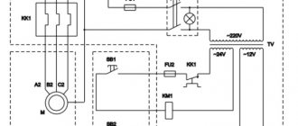
Rice. 2: modernized auto control
Such a circuit, in addition to monitoring the state of the circuits, allows you to determine the plus or minus at the terminals and the signal intensity. Thanks to the multi-polarity of the LEDs, one of them will light up when touching the positive terminal, and the second will signal when contacting the negative terminal.
To implement such autotest control you will need:
- Connecting wires are selected according to your needs, but professional auto electricians recommend making the length at least 2 m, since the probe has to be installed in hard-to-reach places;
- The probes can be plugs or alligators; for one-time use, you can simply strip the edges of the wires from insulation and do without probes;
- The socket for the light bulb and the light bulb itself are 12V , if the lighting device has a different connection principle, a socket of the appropriate type is installed or the wires are soldered to the terminals of the lamp (LED);
- Button – designed for switching in the control circuit, selected according to the value of the switched current;
- Two LEDs - in this example, multi-colored models are used (red for signaling the positive terminal and blue for the negative);
- Housing – designed to accommodate all the parts and install indicator lights in a visible place; a marker, felt-tip pen or plastic tube of glue can be used as a housing.
The choice of auxiliary elements is limited only by your imagination and the available tools that you find in your garage, apartment or workshop. If you are making a car tester for a specific purpose, you can exclude certain elements from the circuit, thereby greatly simplifying the device. Thus, the simplest control is considered to be a model with one light bulb or low-voltage LED.
The simplest 12V control to indicate the circuit
To make such a device, you will need a disposable syringe, a 12 V light bulb (you can replace it with an LED), wire, rubber band, utility knife, and pliers.
The manufacturing process consists of the following stages:
- disassemble the needle from the syringe and thread it into the plastic base so that one end is completely immersed inside the syringe - it should act as a contact for the light bulb.
Rice. 3: needle position in plastic base - measure the length of the wire so that it is convenient for you to wrap it around the base. Strip this area of insulation, wrap it around the lamp and tighten it with pliers. This procedure can be replaced by soldering to ensure more reliable contact.
- If the lamp base moves freely inside the syringe, put a rubber band on top of it to seal it. Insert the lamp so that the unused contact makes contact with the needle.
Rice. 4: Insert the light bulb into the syringe - Cut the plunger from the syringe so that it covers the lamp flush with the body. Make a hole in the piston for the wire, otherwise production may be very difficult.
How to find phase and zero
Let us recall the voltage distribution diagram in a three-phase network made using the TN-C grounding system.
During military service, during exercises, I had to practically solve a similar problem in the field conditions of a training ground. It was necessary to find phase and zero in a six-core power cable connected to voltage in order to power the lighting circuit from them.
There was no indicator or measuring instruments. A messenger was sent for the light bulbs, and we made do with an ordinary electric razor and a piece of insulated wire.
The test was carried out in two stages:
- determination of phase ends;
- search for zero.
Measurement of phase voltages
The work proceeded according to the following scheme:
- they hammered a piece of metal into the ground next to the cable;
- they attached one contact of an electric razor plug to it;
- a piece of wire was screwed to the second pin and secured with threads;
- with the free end of this conductor we touched all the cores of the cable in turn;
- We marked the three wires on which the razor motor started working - this is how we identified the phase ends and chose the one where it would be easier to install the subsequent circuit.
Search for zero
The electric razor plug was removed from the homemade grounding and, using the freed pin, a contact for current was created alternately on the remaining three wires of the cable with a section of wire connected to the selected phase.
When the engine started, it indicated a working zero, and the other two ends were simply in reserve.
Experienced electricians will see many safety violations in our actions. But this example is given for a different purpose - to show the technical feasibility of solving such a task and its implementation with awareness of the risks and dangers. And in a critical situation, a control lamp or indicator can be replaced with any power tool, for example, a home craftsman’s drill.
To better understand the principles of troubleshooting in electrical wiring, I recommend watching the owner’s video “Tips from an Electrician” about the practice of searching for short circuits with a test lamp. I think that they will be useful when using an ordinary voltmeter.
Varieties
There are two types of controls: for home and car. They differ significantly from each other; for a home you can use 220 Volts, while for a car you can only use a 12 Volt control. They are assembled in a similar way, the only difference is the light source that is used. Let's figure out how to make a control with your own hands, and what we need for this. Also read: automatic cabinet lighting
Operating principle of the voltage indicator
Let's consider two options: double-pole/single-pole voltage indicators.
This indicator consists of two insulated wires with probes and a housing with a built-in LED or neon indicator. The condition of the electrical network is checked with probes: if there is a break, the indicator will not light up.
Current flow diagram when checking with a two-pole meter
The principle of operation and the flow of electricity is similar to a control lamp with one fundamental exception: resistance is added inside the indicator housing. The resistor minimizes the amount of current that flows through the two-pole pointer.
A single-pole pointer or indicator screwdriver works on a different principle.
In it, due to the built-in current-limiting resistor, a minimum current strength is created at the output. It is safe for humans. The path of electricity looks like this:
Current flow diagram when checking with an indicator screwdriver
An electric current circuit when checked with an indicator screwdriver: current source - wire - screwdriver - human body - ground. The presence or absence of a glowing indicator will indicate an existing break.
How to make a control with your own hands for a car, at home for 12 and 220 Volts
Due to a large amount of dirt, electrical equipment can also become unusable. An indicator screwdriver or a car light bulb will help identify the malfunction. Also, at the time of a breakdown, the necessary tools and materials must be in the car.
Expert opinion
Strebizh Viktor Fedorovich, leading construction foreman
It was necessary to find phase and zero in a six-core power cable connected to voltage in order to power the lighting circuit from them. If you need an explanation of unclear points, write to me!
We do home inspections
To make a test for home use, you need to prepare the following materials:
- Electric cartridge.
- 220 Volt lamp.
- Copper wires (others are possible), the length of the wires should be at least 50 cm.
- Insulation tape or other protection.
- Probes.
The control connection diagram is as follows.
You just need to connect the wires to the socket and screw in a regular lamp. As you can see, a homemade 220-volt control light has a fairly simple design; even a small child can assemble it with his own hands.
Remember! It is necessary to make high-quality insulation, preferably winding it at the end, so it will be convenient to use. Do not make the tips too large, as they can be accidentally caught by your hand.
See how the professionals do it.
Do-it-yourself auto electrical repairs
Auto electrics is not a difficult matter at all, you just need to understand a little about electricity and be able to recognize faults. They must be eliminated in time so that the car can move unhindered.
A common problem with a car's electrical system is faulty fuses. If the fuse fails, it must be replaced with a new one. The duplicate must be exactly the same denomination as the new one.
You can also fix some other simple breakdowns yourself. If you cannot cope with more complex problems, then it will be easier to seek help from the nearest auto repair shop, where specialists will diagnose and identify all breakdowns. Afterwards they will make a quality repair.
If there is a burning smell in the car interior, it means that there is a short circuit or fire in the electrical wiring. You cannot move in this state; you must stop and open the hood. After this, disconnect the terminals from the battery and call a tow truck, which will take you to a car service center.
Useful tips Connection diagrams Principles of operation of devices Main concepts Meters from Energomer Precautions Incandescent lamps Video instructions for the master Testing with a multimeter