Types of voltmeters
There are electromechanical and electronic devices. Each of them has its own characteristics. The common thing is that when measuring voltage, a series connection of such devices in a circuit is not used. In the diagram, a voltmeter is indicated by a circle with the letter “V” inside it.
Electromechanical devices
There are instruments for determining voltage for direct current and alternating current. Their work is based on the application of the magnetoelectric principle. The device consists of a permanent magnet and a steel core. The arrow is attached to a frame on which a thin wire is wound. When current passes through it, an electromagnetic field is created that deflects the needle.
The angle of rotation of the frame corresponds to the potential difference at the terminals. To reduce needle vibrations, a compensator is used in the device. This can be an induction or air damper, a system of counterweights, etc. Such elements help improve the accuracy of the measurement result and compensate for the influence of gravity on the pointer.
Electronic devices
There are two types of such devices - analog and digital. In the first case, the circuit contains a converter of the measured value into the angle of rotation of the arrow. When an analog voltmeter is connected to an electrical circuit, the alternating voltage is converted to direct voltage. The signal arrives at the detector. It influences the arrow and it deviates at a certain angle.
Digital instruments are more accurate than analog instruments, so the latter are currently practically not used. A digital voltmeter has a display and a converter, with the help of which the measured parameter takes on a digital form. The display of a device connected to a DC network displays the polarity of the connection. The accuracy of readings when measuring voltage with a digital voltmeter largely depends on the quality of the converter.
Why should the ammeter resistance be significantly less than the circuit resistance?
In order for the ammeter not to noticeably change the total resistance of the circuit, its own resistance, as follows from formula (54.2), must be small compared to the resistance of the circuit. Therefore, ammeters are made with very low resistance (a few tenths or hundredths of an Ohm).
Interesting materials:
How many characters are on one Word page? How many story missions are there in Metal Gear Solid 5? How many fairy-tale heroes have pulled turnips? How many declensions do creatures have? How many syllables are pencils? How long do service dogs last? How long does it take to become a police captain? How long does mascara last? How long to serve in the army with a bachelor's degree? How much tar and nicotine is in Winston blue cigarettes?
How does a voltmeter work?
There are two types of voltmeters: analog, which indicate the value by tilting the needle of a mechanical device, and the increasingly used digital ones, equipped with complex electronic circuits.
Analog voltmeters are usually ammeters with a resistor RV in series with a very large electrical resistance value. That is, in essence, they measure the current IV flowing through it, and the scale shows the value, which is the result of the calculation: UV = IV * RV .
Digital instruments, as a rule, have the opposite design (that is, they are voltmeters, not ammeters). This is because making a digital voltage meter is relatively simple. If we connect it in parallel with a low resistance resistor, we get an ammeter. The indicator value can be calculated using the equation: UV = IV * RV .
There is, however, a type of analog voltmeter that does not operate on the same principle as an ammeter. This is an electrostatic voltmeter. In practice, this is a capacitor with one fixed plate and another movable one. The electrical interaction of the plates causes the movement of the pointer attached to the moving part. Using such a voltmeter, you can measure even very high electrical voltages, and the value of its internal resistance is almost infinite.
BY42A connection diagram
Setting up a digital voltmeter and ammeter In general, it is not at all difficult. It was not immediately and at the right time that it became clear that its power input was galvanically connected to the minus input of the shunt. First, without connecting the load, by adjusting resistor R5 we set its readings to zero. The composite resistor turned out to be exactly as much as needed due to the error of one of them: As a result, it now measures, starting from 50mA, up to 50A with a minimum step of about 20mA, 0 also shows.
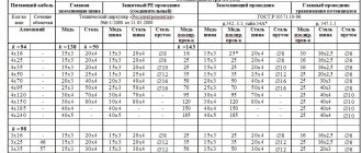
The design and quality of the voltmeters considered are unlikely to be suitable for beautiful tuning. Digital voltmeter circuit. When transmitting high voltage, less current is required for the same power. According to accuracy classes, shunts are divided into: 0.02, 0.05, 0.1, 0.2 and 0.5 - this is the permissible error in fractions of a percent.
An AC voltmeter shows the actual voltage value.
For this method you will need: any 4 or 5-pin automotive relay, for example, I got µV at the input of the op-amp. The voltmeter is assembled on an STM8 microcontroller.
Otherwise, the pointer will point in the opposite direction to the correct direction. Also, in addition to the standard circuit, we will describe how to connect a voltammeter to a charger. How to connect a voltammeter to a charger - a selection of circuits. We have selected the 4 most common voltammeters that craftsmen use in their devices. Installing a voltmeter on a VAZ 2106 part 2
Security measures
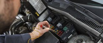
Unlike other devices, such as an ohmmeter or a megometer, when working with a voltmeter, you have to deal with voltage. At small values it does not pose a danger to humans. Great care must be taken when measuring voltages that can create a dangerous current flowing through the human body.
Voltage measurements must be accompanied by full compliance with safety regulations and operating regulations. This will prevent electrical injury. It is prohibited to work without protective equipment, such as rubber gloves and mats. Upon completion of the work, there should be no exposed live parts that could cause accidental contact by maintenance personnel.
The widespread use of voltage measurement in electrical engineering has led to the creation of voltmeters of various designs. They differ both in operating principle and in accuracy. The most popular are universal devices that can automatically select not only the limit, but also the type of controlled value.
Principle of operation
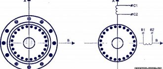
Electromechanical type meters were the first to be created. They operate using the magnetoelectric principle. A permanent magnet is fixedly fixed, and a steel core is installed between its poles. This structural element is installed in such a way that a constant electromagnetic field can be formed in the annular air gap.
A frame made of aluminum is installed in the gap on the axle shafts. She is able to move freely. There is also a spool of thin wire on the frame. The indicator arrow of the device is attached to the frame using springs. As soon as an electric current begins to pass through the device, an electromagnetic field appears in the winding. The frame interacts with it and deflects along with the arrow to a distance corresponding to the voltage value.
The design of the meter also contains an induction damper - an aluminum plate mounted on a frame with an arrow. In accordance with Lenz's rule, eddy currents arising in the damper interact with the magnetic field that generated them and slow down the oscillations of the device pointer. To achieve the required measurement accuracy, the device must not be exposed to gravity during operation.
To solve this problem, the moving part of the meter is equipped with a system of weights moving on rods. In addition, to ensure accurate measurements, it is necessary to reduce the friction force of the steel tips. This is achieved through the use of special wear-resistant steels. Parts made from them are polished.
Before starting the measurement, the user needs to set the indicator arrow to the zero position.
For this purpose, the design of the device includes a special adjustment screw connected to a spring. This is a classic design, but today there are devices containing magnets of different shapes. Moreover, in some designs the magnet is movable.
We recommend reading: Experiment: can chokes conduct electric current
Features of the use of voltmeters in various cases
To get an accurate voltage reading, you need to turn on the measuring device correctly. The connection must only be parallel. It is important to observe polarity. It can be determined by the diagram, which indicates how to correctly connect the measuring instruments. Theoretically, an ideal voltmeter will be as accurate as possible when the internal resistance is very high. In this case, a minimum current will pass through it.
In a real situation, this condition is not met, so the measurement is made taking into account the expected voltage value. In this case, you need to set the voltmeter switch in accordance with the desired range.
The choice of a voltmeter for measuring DC voltage depends on the value of the latter:
- If the voltage does not exceed 1 millivolt, then use devices with a built-in amplifier.
- Up to 1000 volts, conventional measuring instruments of various types can be used.
- If you need to check this parameter in a high-voltage area, then it is necessary to use special electrostatic devices designed to operate in electrical networks with voltages above 1000 V.
To increase the measurement limit, you can use a series connection of additional resistance to the device. In this case, a directly proportional dependence is observed, that is, in order to increase the measurement limit by N times, the resistance should also be increased by N times.
The type of voltmeter for an alternating current network is selected depending on the voltage and frequency of the current:
- To measure a potential difference of less than 1 V, a voltmeter with an amplifier is connected.
- Voltages up to 1 kV and up to 10 kHz in an electrical circuit are measured using conventional instruments.
- When measuring high-frequency alternating voltage, electrostatic and thermoelectric devices are used.
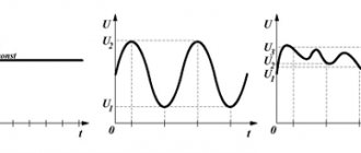
When measuring AC voltage, the device displays the value indicated on the diagram. It is approximately 1.7 times less than the amplitude. If the correct connection diagram is used, the voltmeter will show the most accurate value. When carrying out measurements in electrical networks with alternating current, both resistors and voltage transformers can be used as additional resistance.
Why is the voltmeter in parallel and the ammeter in series?
To measure small currents and voltages, a highly sensitive galvanometer is used - this is the basis and prototype of any pointer measuring instruments. If you connect an additional resistance in series with a galvanometer, you get a voltmeter, and if you connect a shunt in parallel, you get an ammeter.
Despite the fact that digital meters have become very widespread in recent decades, there are still areas of application in which the advantages of pointer instruments are needed, for example, for observing the dynamics of a changing quantity during some transient processes, for measuring changing signals, and so on.
In this article we will talk about connecting voltmeters and ammeters to measure voltages and currents.
How to connect a voltmeter and take measurements?
Voltmeters should always be connected in parallel with the electrical device or element on which the electrical voltage is measured (Figure 2).
Rice. 2. Method for measuring electrical voltage at the ends of element R
The key idea is that the voltmeter terminals are connected to those points in the electrical circuit between which the electrical voltage must be measured .
However, it should be remembered that with such a connection, part of the current IV will flow through the voltmeter, and not through the element being tested R. Thus, we are dealing with a situation where the action of measuring a physical quantity changes the value of this quantity. This is not the only similar example in physics.
As can be seen from the previous discussions, to measure the true value of the electrical voltage at the ends of a circuit element, we need a voltmeter with infinite resistance. Then no electric current will flow through the measuring device, so the measurements will be undistorted. In practice, it is impossible to realize infinite electrical resistance in a voltmeter. However, voltmeters are now sold with extremely high internal resistance, exceeding 100 TOM.
It is worth noting that the read voltage value is always less than the true value. This is an example of systematic measurement error.
The true value of the voltage at the ends of the element R in Fig. 2, according to Ohm’s law for a section of an electrical circuit, is: U = I*R
But, since the voltmeter has internal resistance, it shows the value: UV = IV * RV = IR * R.
After simple transformations, we find that the real value of the electrical voltage at the ends of the circuit element being tested R has the value: U = UV * (1 + R/RV)
This formula confirms our previous statement that an ideal voltmeter should have infinite internal resistance. Since the resistance coefficient in this formula tends to infinity, the measured value of UV tends to the true value of U. Since in reality there is no device that satisfies this ideal condition, when making measurements, it is necessary to select a voltmeter in such a way that the magnitude of the error it introduces is within the expected error measurements.
Conclusion: The higher the internal resistance of the voltmeter, the smaller the measurement error; Therefore, voltmeters always have a very high electrical resistance.
Like an ammeter, a “ + ” sign is placed at one terminal of a voltmeter. This clamp must be connected to the wire coming from the positive pole of the current source. Otherwise, the instrument needle will deviate in the opposite direction. And the negative clamp, accordingly, is connected to the wire coming from the negative pole of the current source.
History of invention
The Italian scientist Alessandro Volta, after conducting a series of experiments with electricity, comes to the conclusion that electric current can be obtained by combining metals with liquid.
By placing copper plates coated with zinc in acid, in 1800 he created the first electrochemical energy source, later called the “voltaic column”. He also establishes that when two different metals are joined, a force is generated, which is expended in the work of moving an electric charge from one point to another. In this case, the displaced charge changes its potential (the amount of energy) it possesses. The difference between the initial potential and the final potential is called “voltage”.
To measure the amount of electricity, Volt uses a metal rod inserted into a rubber stopper and placed in a bottle. He puts straws on the lower end, located in the bottle, and a ball on the other. The scientist observes that when the ball comes into contact with an electrified substance, the straws repel. This allows him to judge the degree of charge of the material.
Volt proved the existence of voltage by conducting the following experiment. A copper and zinc disk was placed on the electroscope (a device that records charge). A thin layer of dielectric is laid between them. For a short time, the physicist connected the metals together with a wire. The petals on the electroscope moved slightly apart. Next, the disks moved apart to a greater distance, while the recorder petals diverged even more.
In fact, this was the first experiment to measure, albeit in rough form, voltage. In 1830, the English scientist Michael Faraday discovered the phenomenon of electromagnetic induction, which was subsequently used to create a number of electrical measuring instruments.
In 1881, French physicist Arsene D'Arsonval created a device consisting of a coil and a pointer placed in a constant magnetic field. Electric current was supplied to the coil, causing the needle to deviate from its initial position. In the same year, the International Electrotechnical Congress was held, at which the designations of electrical quantities were adopted. The device designed to measure potential differences was called a voltmeter, and voltage began to be measured in volts.
How to use a multimeter
When working with the tester, you must follow the recommendations specified in the operating instructions.
Constant pressure
The chain is pre-broken.
- The red probe is connected to the “V Ω ma” connector.
- Black – connects to the “COM” socket.
- The rotary switch selects the estimated DC voltage limit “DCV”.
- If the value is unknown, the maximum is set, then successively decreased by one position.
- The free ends of the probes are connected to the circuit.
- The voltage shown on the display is recorded.
If there is a “HOLD” button, it can be used to “freeze” the current value on the display.
AC voltage
The operating algorithm is similar. Only the rotary switch is moved to the ACV position.
Additional resistor
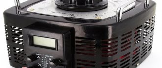
Modern measuring instruments are supplied with an additional resistor connected in series with the winding of the tester or voltmeter. It reduces the load on the coil, part of the voltage falls on the resistance. This value is known in advance and is also proportional to the resistance of the resistor. If there is no such resistor on old laboratory voltmeters, it is connected separately, and then calculations are carried out. Digital measuring devices do this automatically - turning the knob sets the appropriate multiplier.
The maximum measured voltage value depends on the resistance of the additional resistor. For most household testers, the peak voltage is:
- constant – 1000 V or 1 kV;
- alternating – 200 V.
To manufacture the resistor, a material with low temperature resistance is used, which eliminates the dependence of the device readings on thermal parameters.
Share on social networks: October 21, 2022, 14:10 Physics 0.00% 00
Application of a multimeter
In most cases, it is convenient to use specialized instruments to carry out measurements. There are a large number of varieties, the use of which allows serial and parallel connection in a circuit. The connection diagram of the voltmeter implies only a parallel connection.
In some cases, you can use a multimeter. This measuring device operates on a universal principle. It can be used to measure various electrical quantities, including DC and AC voltage. To do this, you need to take the following steps:
- Set the switch to the appropriate mode for measuring DC or AC voltage.
- Select measurement range. To do this, you need to point to the nearest value that exceeds the expected one.
- Connect the black and red probes. The first is inserted into the COM socket, the second into the adjacent one marked V.
- The probes are connected in parallel to the part being measured, maintaining the correct polarity.
- The display shows the measurement result.
After finishing work, the mode switching knob should be moved to the “Off” position. The advantage of using a multimeter is its versatility and ease of use.
Measuring current with an ammeter
An ammeter measures the current in a circuit, through a load or through an individual element. Therefore, to measure current, an ammeter is connected in series
, otherwise similar to the voltmeter:
— When measuring direct current, you need to take into account the polarity, that is, the plus of the ammeter to the plus of the power source, and the minus to the load. You can connect the other way around - the plus of the ammeter to the load, and the minus to the minus of the power source.
— When measuring AC current, polarity does not need to be taken into account.
— When choosing a device, it is also important to pay attention to the type of quantity being measured.
How to connect a voltmeter in a car?
As mentioned above, the easiest voltmeter to connect is one designed for installation in the cigarette lighter socket. You just need to plug in such a device instead of the cigarette lighter itself, and that’s it. You can also use an extension cord or tee for the same connector to install it. This will be convenient if you use the cigarette lighter socket for something else - to power the DVR, charge your smartphone, or for its intended purpose.
With wired models you will have to tinker. First consider a voltmeter that has only two wires. Typically, they always come in two different colors, such as red and black. If the voltmeter you bought is not an outright fake, then the red wire is “plus”, and the black wire, respectively, is “minus” or “ground”.
Any voltmeter in the car is connected directly to the battery. It is better if through a fuse. This is how, by the way, almost all cigarette lighter sockets are connected - directly to the battery through a fuse. It is best to extend the corresponding wires for connecting the voltmeter to the battery yourself. As an alternative, you can try to find the “plus” and “minus” under the instrument panel trim, or in the place where the car radio is connected. However, we repeat, it is best to run separate two wires directly to the battery, installing a fuse in the gap in the positive wire.
How to use a voltmeter in a car?
Now the most interesting thing is how to find out all the information that was listed at the beginning of the article using simple numbers on a voltmeter? Let's go in order.
What % is the battery charged?
The percentage of battery charge can be determined by how many volts it produces at rest. The latter is a very important condition that must be fulfilled. That's why we'll start with it. How to bring the battery to rest? You just need to let it sit for 8-12 hours. The battery is usually in this state in the morning if the car was previously used yesterday and was not parked late in the evening. Overnight, the battery “calmed down”, the voltage on it leveled out, and from it you can determine how many percent it is charged.
How it's done? A fully functional car battery at rest should produce a voltage from 11.7 V to 12.7 V. Moreover, if the voltmeter shows 12.7 V, then the battery is 100% charged, and if 11.7 V, then it is on the contrary, it is discharged to zero. Let us remind you that the battery must be settled, and no load (music, dimensions, gadgets, etc.) must be turned on at the time of measurements.
The beauty of this method is that from the voltage of the battery, which is at rest and without load, intermediate values can be determined as a percentage. To do this, it is enough to compare tenths of a volt with tens of percent. For example, if the battery voltage is 12.6 V, then subtract 10% from 100%, and we get the battery charge to 90%. Accordingly, 12.5 V is 70%, and so on, until completely discharged.
Before you start using this technique, it would be a good idea to check the leakage current when the car is turned off and all devices are turned off. If any consumers are in sleep mode, they can draw quite a lot of current from the battery. This will cause a voltage drop, and the data obtained using the described method will be inaccurate. The most accurate % can only be found when the battery is completely disconnected from the on-board network. If the leakage current is normal (50-100 mA), then the charge percentage will be very accurate.
How does the battery hold the load while starting the engine?
During operation of the starter, the battery experiences the greatest load, incomparable to other consumers of the car. The currents at this moment reach hundreds of amperes, which causes a very noticeable voltage drop even on a new and fully charged battery.
So here it is. If you pay attention to the voltmeter while starting the engine, you can find out how well your battery can handle a heavy load. If the battery is fully operational and not very worn out, then the drawdown should be no more than 2-3 tenths of a volt. That is, if you got into the car in the morning and the voltage was 12.5 V, and during the process of starting the engine it dropped to 12.3 V, then this indicates that the battery is holding the load perfectly.
This method, by the way, allows you to determine not only the health of the battery, but also the starter itself. If, for example, you have a completely new (or relatively fresh) battery installed, which you are confident in, and the voltage drop at start is still huge (drops to 11-10 V or lower), then this means that there are obvious problems with the starter . It either jams, or there is wear on the brushes, or a short circuit in the windings. Poor contact at the starter terminals can also cause specific voltage drops.
Is the battery charged normally from the generator?
When the engine is up and running, the alternator must produce electricity, some of which is returned to the battery, charging it. To determine that charging actually occurs and allows you to determine the device in question here.
How much should the voltmeter show when the car is running? Here the indicators vary quite a lot on different cars. If we take the ideal voltage, which indicates a fully charged battery, then it corresponds to 14.4 V. But there are several nuances.
- Firstly, if the battery was heavily discharged before starting the engine, then in the first minutes the charge voltage will be slightly lower than it should be. It may even be less than 14 V (13.7-13.8, for example). This is fine. Over time, it will increase and reach the specified parameter.
- Secondly, normally the charge voltage differs on different cars. It depends on the generator, and on the speed of rotation of the crankshaft, and on the characteristics or serviceability of the relay regulator. In general, if the charge voltage is very different from the ideal 14.4 V, then you should take your car to a good auto electrician.
- Thirdly, at negative ambient temperatures, it is believed that the battery is generally not able to accept a charge from the generator for the first half hour. It follows that immediately after starting in severe frost, the charge voltage will be far from ideal. If the entire system is working properly, then after warming up the engine compartment and the battery itself, the voltmeter readings will level out.