Single-phase asynchronous electric motors with a power of up to 1 kW, rarely up to 2 kW, are widely used in conditions where there is only a single-phase network, for example, to drive mechanisms of various devices, electrified tools, in household mechanisms, etc. If the motor winding is powered with single-phase current, then the electromagnetic field in it will not be rotating, as in three-phase machines, but pulsating, the energy performance will be worse than that of three-phase machines, but. the starting torque will be zero, i.e. the engine will not start without special devices. Therefore, in the stators of single-phase motors, two windings are installed, which are often also called winding phases. One of them is main, or working, the other is auxiliary. The windings are located along the stator slots so that their axes are shifted relative to each other in space by an electrical angle of 90° (Fig. 1).
Fig.1. Winding axes of two- and single-phase motors: a - location of coils of different phases in the stator slots; b - conventional representation of the winding phases.
If the phases of the winding currents are not the same, i.e., shifted in time, then the electromagnetic field in the motor stator becomes rotating. The energy performance of the engine improves and starting torque appears. When the phases of the currents are shifted by an electrical angle of 90° and the MMF windings are identical, the field becomes circular and the efficiency of a single-phase motor will be greatest. This can be achieved by making both motor windings identical and connecting a capacitor in series to one of them (Fig. 2.a). Such motors are called single-phase capacitor motors.
Rice. 2.. Switching circuits for single-phase motors: a - with a permanently switched on capacitor (capacitor motors); b - with working and starting capacitors; c - with a starting element; Ср - working capacitor; Sp - starting capacitor; PE - starting element.
The capacitance of the capacitor required to obtain a circular field depends on the active and inductive resistance of the motor windings and on its load. For single-phase capacitor motors, the capacitor is designed so that the field is circular at rated load. It is connected in series with one of the phases of the windings for the entire operating time. This capacitor is called the working capacitor and is designated Wed. When starting the engine, the capacitance of the working capacitor is insufficient to form a circular field and the starting torque of the engine is small. To increase the starting torque, a second starting capacitor (Cn) is connected in parallel with the working capacitor. The total capacitance of the starting and operating capacitors ensures that a circular rotating field is obtained during engine starting and its starting torque increases. After the engine accelerates, the starting capacitor is turned off, and the working capacitor remains turned on (Fig. 2.b). Thus, the engine starts and runs at rated load with a rotating circular field.
Rice. 3. Scheme of a single-layer concentric winding with m = 2, z = 16, 2p = 2, made in a waddling manner.
The stators of most single- and two-phase motors use random single-layer windings with concentric coils (Fig. 3). They have either four terminals - the beginnings and ends of the main and auxiliary phases, or only three. With three outputs, the ends of the main and auxiliary phases are connected to each other inside the housing and a wire is led out from the place where they connect to the common point of the winding.
Rice. 4. Scheme of a single-layer concentric winding with m = 2, z = 24, 2р = 4, q = 3, made with “combed” coils.
To reduce the overhang of the frontal parts of the coils, single-layer windings are often waddled. If the number of slots per pole and phase is even, then the waddling windings are essentially no different from the same windings of three-phase machines. If the number q is odd, then the large coils in groups are made “combed”, that is, the frontal parts of half of their turns are bent in one direction, and the other half in the other direction (Fig. 4). The need to install capacitors increases the cost of single-phase motors, increases their size and reduces reliability, since capacitors fail more often than motors. Therefore, most single-phase asynchronous motors are designed to operate with only one - the main winding. However, in order for them to be started, a second winding is also installed - an auxiliary winding, which is often called a starting winding. It is intended only to create a rotating field when starting the engine. Such single-phase motors are called motors with a starting phase (or with a starting winding). The phase shift of the currents of the main (working) and starting windings is achieved by changing the resistance of the starting winding by connecting in series with it the so-called starting element (Fig. 2.c) - a capacitor or resistor (most often a cheaper one is used - a resistor). Starting windings, as a rule, differ from working windings in the number of turns, the number of coils, and the cross-section of the wire. They usually occupy 1/3 of all stator slots. The remaining 2/3 of the slots contain the working winding. The connection diagrams and number of poles of the working and starting windings are the same (Fig. 5).
Features of repairing an asynchronous machine
Engine problems of any type can be mechanical or electrical in nature. In the first case, strong vibration and characteristic noise may indicate a malfunction; as a rule, this indicates problems with the bearing (usually in the end cover). If the malfunction is not corrected in time, the shaft may jam, which will inevitably lead to failure of the stator windings. In this case, the thermal protection of the circuit breaker may not have time to operate.
“Burnt” wires of the stator winding
Based on practice, in 90% of failures of asynchronous machines, problems arise with the stator winding (break, interturn short circuit, short circuit to the frame). In this case, the short-circuited armature, as a rule, remains in working condition. Therefore, even if the damage is mechanical, it is necessary to check the electrical part.
Tools and accessories
In order to independently rewind the armature of an electric motor with your own hands, you will need the following tools and devices.
- A multimeter or voltage indicator, as well as a 12 V lamp (power no more than 40 W), a megger.
- Winding wire, its diameter must be exactly the same as on the failed electric motor.
- Dielectric cardboard 0.3 mm thick.
- Electric soldering iron.
- Thick cotton threads.
- Epoxy resin or varnish.
- Sandpaper.
Before starting work, it is necessary to accurately determine the damage. To do this, you need to visually inspect the electric motor and check whether there is voltage going to the collector. Carry out diagnostics of the start button, ring it using a multimeter. Only if the power circuit is fully operational, it is necessary to disassemble the electric motor and repair it.
Winding check
In most cases, the problem can be detected by its appearance and characteristic odor (see Figure 1). If the fault cannot be determined empirically, we proceed to diagnostics, which begins with a continuity test. If one is found, the engine is disassembled (this process will be described separately) and the connections are thoroughly inspected. When no defect is detected, a break can be established in one of the coils, which requires rewinding.
If the continuity test does not show a break, you should proceed to measuring the winding resistance, taking into account the following nuances:
- the insulation resistance of the coils to the housing should tend to infinity;
- for a three-phase drive, the windings must show the same resistance;
- For single-phase machines, the resistance of the starting coils exceeds the readings of the working windings.
In addition, it should be taken into account that the resistance of the stator coils is quite low, so to measure it it makes no sense to use devices with a low accuracy class, such as most multimeters. You can correct the situation by assembling a simple circuit using a potentiometer with the addition of an additional power source, for example a car battery.
Circuit for measuring winding resistance
The measurement procedure is as follows:
- The drive coil is connected to the circuit presented above.
- The potentiometer sets the current to 1 A.
- The coil resistance is calculated using the following formula: , where RK and UPIT were described in Figure 2. R is the resistance of the potentiometer, and is the voltage drop across the measured coil (shown by a voltmeter in the diagram).
It is also worth talking about a technique that allows you to determine the location of the interturn short circuit. This is done as follows:
The stator, freed from the rotor, is connected through a transformer to a reduced power supply, having previously placed a steel ball on it (for example, from a bearing). If the coils are working, the ball will move cyclically along the inner surface without stopping. If there is an interturn short circuit, it will “stick” to this place.
Steel ball testing
Creating a platform and establishing contacts
Warm up the glue gun for 10 minutes, this is necessary so that the glue has good properties and sticks well to the surface of the plywood.
Take a piece of plywood and make 4 drops along the edges; in our case, this is necessary for the stability of the platform. Then take the battery, squeeze the glue onto the platform and press it firmly until the glue hardens.
We will use ordinary pins as contacts for the coil; they can be found in any store. Take electrical tape and attach the pins so that they are perpendicular to the board.
If you are not sure that it will hold the wire spool well, you can also secure it with hot glue. Attach a small magnet to the top of the battery with glue; if it has a metal case, the magnet itself will stick to the battery.
How to make an electric motor with your own hands: 120 photos and videos of creating and manufacturing an electric motor
The phase and zero potentials are applied to the beginnings of two windings, and the third is connected through capacitors. They are divided into two chains: a working chain, permanently mounted, and a starting chain, activated via a switch.
Expert opinion
Viktor Pavlovich Strebizh, lighting and electrical expert
Any questions ask me, I will help!
To rewind electric motors with your own hands, you must have at least a minimal understanding of how to connect motor windings. If there is something you don’t understand, write to me!
Features of repair of commutator drives
This type of electric machine is more likely to experience mechanical failures. For example, brushes worn out or commutator contacts clogged. In such situations, repairs come down to cleaning the contact mechanism or replacing graphite brushes.
Testing the electrical part comes down to checking the resistance of the armature winding. In this case, the probes of the device are applied to two adjacent contacts (lamellas) of the collector, after taking readings, measurements are taken further in a circle.
Checking the armature winding of a commutator motor
The displayed resistance should be approximately the same (taking into account the instrument error). If a serious deviation is observed, then this indicates that there is an interturn short circuit or open circuit, therefore, rewinding is necessary.
Electric motor winding diagrams. Rewinding the stator of a grinding machine
- U - with a limit of 90 ⁰C, materials - paper, cotton fabric, silk and yarn without impregnation.
- A - with a limit of 105 ⁰C, the same materials, but with impregnation.
- E - with a limit of 120 ⁰C, materials - organic and synthetic film.
- B - with a limit of 130 ⁰C, materials - fiberglass, mica, asbestos with organic binders.
- F - with a limit of 155 ⁰С, the same materials, but with synthetic impregnating and binding materials.
- H - with a limit of 180 ⁰С, the same materials, but with organosilicon impregnating and binding materials.
- C - with a limit above 180 ⁰C, materials - glass, ceramics, quartz, mica with or without inorganic binders.
Motor winding data
This is a reference data, so the most reliable way to obtain this information is to consult the appropriate sources. This data can also be provided in the product passport.
You can find advice online that recommends manually counting the turns and measuring the diameter of the wire when rewinding. It's a waste of time. It is much easier and more reliable to find all the necessary information using the engine markings, which will indicate the following parameters:
- rated operating characteristics (voltage, power, current consumption, speed, etc.);
- number of wires for one slot;
- Ø wire (as a rule, insulation is not taken into account in this indicator);
- information on the outer and inner diameter of the stator;
- number of grooves;
- with what step the winding is performed;
- rotor dimensions, etc.
Below is a fragment of a table with winding data for electric machines of type 5A.
Example of a table with winding data
Step-by-step instructions for rewinding an electric motor with your own hands
It is necessary to immediately warn that without special equipment and operating skills, rewinding reels will most likely be a useless task. On the other hand, negative experience is also experience. Understanding the complexity of a process is the best explanation of its cost.
The first stage is dismantling
We present an algorithm of actions for asynchronous machines, it is as follows:
- Disconnect the drive from the network (380 or 220 V).
- We remove the electric motor from the structure where it was installed.
- Remove the rear cooling fan shroud.
- We dismantle the impeller.
- We unscrew the fastening of the end covers, and then remove them. It is advisable to start from the front part; after dismantling it, the rotor will easily “come out” from the rear cover.
- We take out the rotor.
This process can be greatly simplified if you use a special device - a puller. With its help, it is easy to free the motor shaft from a pulley or gear, and also remove the end covers.
Puller for dismantling
We will not provide instructions for disassembling a commutator motor, since it is not particularly different. The structure of an electric machine of this type can be found on our website.
Stage two - removing the winding
The sequence of actions is as follows:
- Using a knife, remove the bandage fasteners and insulating coating from the wire connections. Some instructions recommend recording the wiring diagram, for example, by taking a photograph. There is no particular point in doing this, since this is reference information and finding it out by engine brand is not a problem.
- Using a chisel, knock off the tops of the wires from each end of the stator.
- We release the grooves using a punch of the appropriate diameter.
- We clean the stator from dirt, soot, and impregnation varnish.
At this stage, we recommend stopping, picking up the housing and taking it to specialists. Independent dismantling will reduce the cost of restoration work. As mentioned above, without special equipment it is quite difficult to rewind reels efficiently. To understand the complexity of the process, we will describe its technology, which will make the choice easier.
Stator rewinding (final phase)
The process consists of the following steps:
- Installation of insulators in each groove (sleeving).
- The thickness of the material and its characteristics are selected from the reference book.
- Winding data is determined by motor brand.
- A special machine is used to wind the required number of turns of loose coils. You can find photos and parameters of homemade manual machines on the Internet, but the quality of their work is quite questionable.
Bulk Winding Machine - The coil groups are placed in the grooves, after which they are tied and connected. These processes are quite complex and are performed manually.
- Impregnation is carried out. To do this, the body is heated to a temperature of 45°C - 55°C and completely immersed in a container with impregnating varnish. It makes no sense to varnish the wires, since in this case there will still be voids.
- After impregnation, the body is placed in a special chamber, where drying is carried out at a temperature of 130-135°C.
- Final testing of the coils with an ohmmeter.
- Assembly and test run (if only the body, but also other parts and fasteners were transferred for repair).
If only the body was submitted for restoration, we recommend checking the coils before turning on the motor.
Disassembling an asynchronous motor
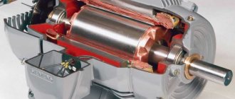
Before rewinding the stator of an asynchronous electric motor, it is necessary to completely disassemble it. To do this, you will need to use a puller, since the covers are mounted on the bearings very tightly. Try to carry out all work as carefully as possible to prevent destruction of the cover and damage to the winding.
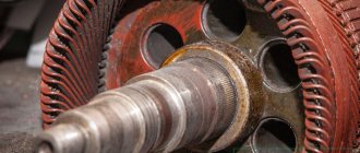
Squirrel-cage rotors very rarely break, so there is no need to touch it during repairs. Only the windings on the stator need to be changed. If there is blackening on the wires, this indicates a breakdown in the engine. All connections in asynchronous motors are practically invisible, since they are very well insulated, because they are fastened with a bandage.
Rewinding the armature
The process of replacing the winding of a commutator motor is somewhat similar, with the exception of small nuances associated with the design features. For example, the armature is sent for rewinding, not the housing, provided that the problem does not arise with the excitation coils. In addition, there are the following differences:
- For winding, a special machine with a more complex configuration is used.
- Grooving, balancing of the armature (in the final part of the process), as well as its cleaning and grinding are required.
- The manifold is cut using a special milling machine.
The above processes require special equipment; without it, rewinding electric motors is a waste of time.
Checking the electric motor after repair
Next we carry out the verification procedure. First, you need to “ring” the device again, as described at the beginning of the article when diagnosing the problem. It is necessary to exclude the possibility of breakage, lack of contact and short circuit of any kind. If the engine passes these checks, it's time to start testing for functionality. To do this, do not immediately connect it to the existing power supply. In industrial facilities, the voltage is 380 V. This is quite a lot. Using a step-down transformer, you should test the operation of the motor.
If it rotates without problems and does not smoke, then the job was done correctly. The engine can be used for its intended purpose.
Thus, the instructions for rewinding an electric motor at home are complete. Good luck to everyone in your new achievements!
Useful tips Connection diagrams Principles of operation of devices Main concepts Meters from Energomer Precautions Incandescent lamps Video instructions for the master Testing with a multimeter

