Recently, “out of production necessity,” I was looking for a circuit for a homemade power regulator, and made the device itself. I was quite pleased with the result, and then I’ll tell you how to make a power regulator with your own hands.
Source ytimg.com
A little about the triac power regulator and how to use it
Triac power regulators, which should now be called dimmers, have flooded our radio market.
Today, such devices can be found even in departments selling distillers, because dimmers are sometimes used to regulate the heating temperature of the material in distillation apparatuses.
These power regulators are also used in electric heaters for water tanks, incubators, vulcanizers for sealing car tubes, in tools - soldering irons for smoothly adjusting heating, in drills and grinders for controlling rotation speed, in simple incandescent lamps for adjusting brightness and even in moonshine stills.
In short, there are a huge number of ways to use power regulators; dimmers are very useful in economic and technical activities and are necessary devices for every workshop.
Source electronoff.ua
What does its power depend on?
Next we will talk about the nuances, of which there are only three, and on which the power of a dimmer, both factory and homemade, can depend.
The first nuance is the power reserve of the triac.
It should be about 30% for high-quality work, and the difference in their price will be insignificant.
For example, we can take a standard situation - you order a triac from a seller, who, in turn, will claim that its power reaches 4 kW.
At the same time, he will use various tricks, for example, he will take a close-up photo to deceive the eye and the heat sink will appear larger than it actually is.
Of course, if you turn on such a dimmer for half a minute, it can and will withstand it.
However, usually incandescent lamps or heating elements are connected to it, which work for hours at this power.
Such regulators will not withstand it, even at 3 kW they will heat up to the maximum, and then they will simply burn out.
You must understand what 40 kW is, and also that the regulator will have to pass 18 amperes through itself and what cross-section the wires must have in order to pass such a current.
The second nuance was touched on a little in the last paragraph, but still - the cross-section of the wires is more expensive than the printed circuit board.
The wider and thicker the cross-section of wires and tracks, the better, and the shorter the tracks and wires themselves, the better.
When soldering them, you must tin them with tin or solder a copper core along the tracks.
Additionally, if you are working with a device of 3,000 W or more, then it is better to abandon the various clamp terminals and any connectors.
After all, these places become vulnerable areas - if the contact weakens a little, then they heat up, and then the wires burn, which, of course, is undesirable.
Source stroykadoma.org
The third nuance is the heat sink.
If the heat sink for your home-made dimmer is not large enough, then after long-term use the entire device will become extremely hot (the temperature can reach 90 degrees Celsius and higher), it will be a real oven.
Therefore, I advise you to use a radiator from a computer with a cooler as a heat sink.
Such replacements for the heat sink, even small ones, will show good results during long-term operation at a power of 4,000 W, while Chinese radiators in the heat sinks will allow the device not to fail in the next few minutes after starting at such power.
Additionally, I’ll tell you a little about glass fuses.
Briefly about the main thing! I do not advise.
I somehow brought the fuse holder with a cap to the rear panel, set the fuse to 15 amperes, the load was about 3 kW.
As a result, the entire assembly became so hot that you couldn’t touch it with your hand.
Therefore, it is better to install automatic switches instead of glass fuses (if the load is 3,000 W, then a 16-amp switch).
Source evse.com.ua
The schematic diagram of the power regulator shown in Figure 14 has been published, in one form or another, more than once, and in more than one publication. Its difference from its predecessors is that it incorporates the most successful components, namely: the load is turned on only at the moment of transition, the sinusoid of the supply voltage through zero, which makes it possible to get rid of interference on the 220 V power supply network. A triac of arbitrary power is used as a power switch. The internal supply voltage stabilizer has increased reliability and noise immunity.
Figure 14 Schematic diagram of the power regulator of heating devices
An analogue of a multivibrator with an adjustable duty cycle, which depends on the position of the variable resistor R1, is assembled on elements DD1.1 and DD1.2. Resistors connected from the extreme terminals of R1 determine the minimum operating/resting time of the heating elements, however, reducing them to less than 620 ohms is not recommended (the device may lose operation stability). The driver is assembled on elements DD1.3 and DD1.4. You can use K561LA7 or K561LE5 as DD1, because the elements are used as ordinary inverters (for more stable operation of the multivibrator, it is better, of course, to use K561TL1). The disadvantages of this kind of power regulators include the fact that they have a relatively small time constant. The intervals between turning on/off the load cannot exceed 1-1.5 minutes. Increasing the timing resistor and capacitors usually leads to a decrease in operating stability, because The leakage currents of the electrolytic capacitor begin to affect. From all of the above, it is not difficult to guess that with a sufficiently large load power, household members are doomed to observe a minute-by-minute increase/decrease in the brightness of lighting fixtures. Constant changes in illumination tire the eyes very much, especially when reading. To increase the work/rest time of the load, it is necessary to introduce additional timing elements, which means an increase in the current consumed by the device. This fact no longer allows the use of a small-sized capacitor shunt to power the device, and the use of a power transformer can significantly expand the functionality of the device. Trying to take into account all the mentioned facts, an automatic power control device for medium and high power heating devices was developed, used in conjunction with water (oil) heating systems. TECHNICAL CHARACTERISTICS OF THE POWER REGULATOR: Supply voltage 180-260 V; The switched load power is determined by the triac or starter used; Work/rest time minimum 5 minutes; Work/rest time maximum 4 hours; The range of set temperatures of the working fluid is 60-100°C; Temperature capture range 30°C; The operating mode is continuous, around the clock. In Fig. Figure 15 shows a schematic diagram of the control device for the electric heating system, Figure 16 shows the location of the conductors on the printed circuit board, Figure 17 shows the location of the parts.
Figure 15 Schematic diagram of a power regulator for high-power heating devices
Figure 16 Drawing of the power regulator printed circuit board (scale 1mm=4px, view from the parts side)
Figure 17 Location of parts on the power regulator printed circuit board
When the contacts of switch SA1 are closed, the mains voltage is supplied to transformer TV. The alternating voltage from the transformer, 25-27 V, is rectified by a diode bridge assembled on diodes VD1-VD4, smoothed by capacitor C5 and stabilized by DA1. A stabilized 24 V voltage serves to power the starter control relay, which in turn supplies power to the heating elements. This voltage is also supplied to the integrated stabilizer DA2, which powers the control circuit. A master oscillator with two operating frequency control circuits is assembled on elements DD1.1 - DD1.3. This made it possible to independently adjust the time of load operation and rest. On DD2, DA3 there is a timer that significantly increases the time constant, on DA3 there is a thermostat that turns off the load when the temperature of the circulating liquid reaches close to boiling. When supply voltage is applied to the 11th pin (input “R”) of the DD3 microcircuit, through the charging capacitor C3, a log level is briefly formed. “1”, which in turn sets the counter to the “zero” state (at all outputs the level is logical “0”). Thus, a log level prohibiting operation appears at the input of element DD1.1. "0". At the output of DD1.4 a log level is formed. “1”, current will begin to flow through the base-emitter junction of transistor VT1 and it will open, relay K1 will turn on and supply voltage to the starter, and it, in turn, to the heating elements. Resistor R6 and capacitor C4 are introduced to reduce current consumption in heating mode. Log. “1” from the output of DD1.4 will also go to the input of DD1.3, thereby allowing its operation, and the clock generator will begin to produce rectangular pulses. The frequency of these pulses depends on the capacitance of capacitor C2 and the sum of resistances R2 + R4. Resistor R4 limits the maximum frequency of the generator, R2 regulates it. The frequency change factor can be approximately calculated using the formula R2/R4 (according to the scheme - 47k / 1.5k = 31, i.e., with the upper position of the R2 engine, according to the diagram, the frequency will be 31 times greater than with the lower one). The pulses generated by the clock generator are supplied to the input of the DD2.1 counter, where their frequency is reduced by 16 times. From the output of the 4th digit of the counter DD2.1 (pin 14), the pulses arrive at the input of DD2.2 and again their frequency decreases by another 16 times. Thus, at a generator clock frequency of 1 kHz, pulses with a frequency of about 4 Hz are formed at the output of the 4th bit (pin 6). This frequency is supplied to the input of the counter DD3 and, through the current-limiting resistor R20, to the LED VD5. Diode VD5 serves to roughly control the frequency of the clock generator. With the appearance of pulses at input “C”, the counter DD3 begins counting them and as soon as a log appears on its 13th bit (pin 3). “1” element DD1.4 will turn off the relay and prohibit the operation of element DD1.3. However, the clock generator will continue to operate, because with the appearance of “1” on the 3rd pin of DD3, the operation of element DD1.1 will be allowed. Now the frequency of the clock generator depends on the capacitance C1 and the position of the resistor R1. After some time, a log will appear on the 3rd pin of DD3. "0" and the cycle will repeat. The DA3 chip contains a thermostat that prevents the working fluid from reaching boiling point. Resistors R17, R18 are installed at the outlet of the water/oil heating boiler, directly on the pipe. Resistor R9 sets the temperature control limit, R10 regulates the maximum temperature itself. As the temperature increases, the total resistance of resistors R17 and R18 will begin to decrease, and as soon as it reaches a value at which the voltage at pin 2 of DA3 becomes less than at pin 3 at the output (pin 6), a log level will be formed. "1". This voltage will open transistor VT2, and it in turn will close VT1, the relay will turn off and the heating will stop. DA3 is covered by an adjustable positive feedback (R12+R14), thereby making it possible to regulate the on/off temperature difference. When using an automatic machine to control oil heaters, it should be taken into account that the oil temperature can reach 120-160°C, and the destruction temperature of semiconductor elements can reach 100-120°C. Almost all thermistors are based on a semiconductor, therefore, to increase the reliability of the device, it is recommended to install the thermistor through a small heat insulator, for example, a newspaper folded into 8-12 layers. Of course, the accuracy of the temperature sensor will decrease, but those 10-20°C parameters will not play a big role. DA1 and DA2 are mounted on a common heat sink, which can be used as an aluminum strip 25-30mm wide and 120-150mm long. The strip is bent until it comes close to the heat-transfer plates m/s DA1 and DA2. The remaining length is bent at a right angle to the edge of the board so that the strip covers part of the perimeter of the board. Almost any type of case is suitable for the device; all controls and buttons are fixed on the front panel, and the fuse panel and starter connection terminals are fixed on the rear panel. Button SA2 without fixation serves to force heating on and is used to increase the duration of the first heating system activation. If you use a latching button as SA2, then it will serve as a switch for the type of work - turning on the load depending on time or the temperature of the working fluid. On the printed circuit board, the DD3 input, as well as the output, “hangs” in the air. This is done to increase the versatility of the device and allows you to change the capacitance C1, C2 within a wide range (install what is available), and adjust the timing diagrams to almost any heating system. After determining the required time intervals, the input and the required output of DD3 are connected by a jumper wire to the required pad.
Site administration address
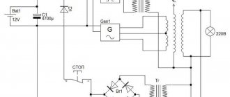
Power regulator circuit
The main control element is the BTA06-600 triac, which is also a triac.
You can replace it with almost any triac from the BTA series, for example BTA12-60, BTA24-600 and others.
In this case, it is possible not to recalculate the nominal values of the elements.
When buying a triac, keep in mind that the first numbers are the maximum current that it passes in the open state.
The second group of numbers is the maximum reverse voltage of this triac.
For example, let’s take the BTA06-600 triac - it turns out that its current is 6 amperes and the voltage is 600 V.
It is enough to adjust a device whose load will be 800 W.
Source motronix.co.il
I also advise you to take a current reserve when choosing a triac - changes in price will be insignificant, but the reliability of the design will increase.
The power of resistor R1 should be 0.25 W so that even when using a 3000 W regulator, the resistor will be cold.
There are no special requirements for a variable resistor, so you can take any one you like.
Capacitor C1 must be film and with a voltage of 400 V.
The fuse should be selected depending on the load current.
The LED can not be installed in the circuit, but then instead of the VD1 diode you will have to install a jumper.
Fuse F1 can be installed on a separate block or on the wire itself, with the cap of its housing located on the rear panel of the device.
Regulator for powerful heater
On the pages of the magazine “Radio” and in other amateur radio literature, many different designs of power regulators are described, from simple ones based on a single thyristor to rather complex ones with microcontroller control. However, the vast majority of designs of these regulators use a phase method for controlling output thyristors, so such regulators inevitably create impulse noise, the intensity of which increases with increasing load power.
To control loads that have significant inertia, such as electric heaters, another method of power control is more suitable - changing the number of full periods of mains voltage passing through the load. This method, unlike the phase method, allows the output thyristors to open at the very beginning of each half-cycle of the mains voltage, which significantly reduces the level of interference created by the power regulator.
An additional advantage of this method is the possibility of using a triac solid-state optoelectronic relay as an output switching element, which contains a detector for the network voltage zero crossing. Such relays are controlled by constant voltage and allow switching currents of tens and hundreds of amperes, so an output node built using a solid-state relay is relatively simple.
The power regulator described in [1] operates on the principle of changing the number of half-cycles of the mains voltage passing through the load, and a modified version of this design, described in [2], allows you to control power by changing the number of full periods of mains voltage passing through the load, which eliminates the appearance of a constant component of the current flowing through the load. Both designs of regulators are built using two CMOS structure microcircuits, and power regulation is carried out in ten steps by changing the division coefficient of the counter, the input of which receives pulses at the network frequency.
When the author needed a regulator for a 4 kW electric heater, the choice fell on the design described in [2], but the device circuit was redesigned taking into account the available parts. The result was a regulator built on a single chip and having sixteen stages of power control. A triac solid-state relay is used as an element that switches the load power circuit, and the elements of the regulator control device do not have a galvanic connection with the 230 V network.
Rice. Regulator circuit
The regulator diagram is shown in the figure. During each positive (relative to the neutral wire) half-cycle of the mains voltage, current flows through the emitting diode of the optocoupler U1, so the phototransistor of the optocoupler opens at the beginning and closes at the end of each positive half-cycle, forming almost rectangular pulses at the input C2 (pin 2) of the DD1.1 counter, the next ones with a frequency of 50 Hz. As each pulse falls, the DD1.1 counter increases its state by one, and a binary code is formed at its outputs, corresponding to the number of calculated full periods of the mains voltage. After the 16th pulse arrives at the input, the counter overflows and the counting of pulses begins again.
The DD1.2 counter works as an RS trigger and ensures that the number of full periods of mains voltage required for the set power level is passed into the load. After each overflow of the DD1.1 counter, a voltage drop is formed at the C2 input (pin 10) of the DD1.2 counter, as a result of which the DD1.2 counter increases its state by one and is self-blocking by applying a high logical level to the C1 input (pin 9) from output Q1. The voltage at this output opens the field-effect transistor VT1, the drain circuit of which includes the emitting diode of the triac solid-state relay U2, which supplies mains voltage to the load. When a high logical level counter DD1.2 appears at input R (pin 15), it returns to its original state, the field-effect transistor closes and the load is disconnected from the network.
Switches SA1-SA4 are used to set the power allocated to the heater. Each of the switches connected through an isolation diode to the corresponding output of the meter DD1.1 has its own weight, corresponding to the number of full periods of mains voltage supplied to the load as a percentage of the total power. If only switch SA1 is closed, the load will receive only one of the sixteen periods of mains voltage, which corresponds to 100/16 or 6.25% of the full load power. When switch SA2 is closed, two out of sixteen periods will be supplied to the load, i.e. 12.5% of the power, and when several switches are turned on simultaneously, the power will be determined by the total weight of these switches. Thus, the device provides 16 stages of load power regulation, starting from 0 (all switches are open) and up to 93.75% (all switches are closed) in steps of 6.25%.
The regulator works as follows. With each overflow of the counter DD1.1, the counter DD1.2 goes into the single state at output Q1 and turns on the solid-state relay U2, which remains on for the number of full periods of the mains voltage specified by switches SA1 - SA4. When the outputs of counter DD1.1 reach a binary number corresponding to the power level set by switches SA1-SA4, a high logical level appears at pin 15 of counter DD1.2 and the trigger built on this counter returns to its original state, turning off the solid-state relay. The next time counter DD1.1 overflows, the trigger switches again to the single state, and the process repeats.
Diode VD6 is used to ensure correct operation of the regulator at a set power of 50%. The fact is that if only switch SA4 is turned on, the drop in the high logical level at pin 10 of counter DD1.2 will coincide with the drop in the high logical level at its reset input, so the counter DD1.2 will not be able to switch and the power on the load will be zero. The presence of the VD6 diode ensures that a low logical level appears at the R input of the DD1.2 counter immediately after the reset signal passes, thereby ensuring correct operation of the counter at a set power of 50%.
Switch SA5 is used to control the operating mode. In the “Regulator” position, the negative terminal of the solid state relay U2 is connected to the output of the power regulator, in the “Off” position. the load is turned off, and in the “Full power” position, the load receives all the mains voltage and the regulator does not work. By the frequency of flashes of the HL1 indicator LED, you can roughly judge the amount of power supplied to the load. Capacitors C2-C4 suppress noise at the corresponding inputs of the DD1 microcircuit, capacitor C1 is a blocking capacitor in the power circuit of this microcircuit.
The device is powered by a stabilized voltage of 5 V coming from the output of the switching power supply A1 (a charger for a cell phone model WTCS2 with a load current of up to 700 mA is used). To power the device, you can also use any suitable stabilized source with an output voltage of 5...14 V and a load current of at least 50 mA, increasing the resistance of resistors R1, R3, R5 in proportion to the value of the supply voltage. In the case when the power source is located at some distance from the regulator board, an oxide capacitor with a capacity of 220 μF for a rated voltage of 16 V should be connected in parallel with capacitor C1.
The device can use resistors of any type, but the power of resistor R2 must be at least 1 W. Non-polar capacitors - K10-7V or K10-17, diode VD1 - with a permissible reverse voltage of at least 400 V, the rest of the diodes - any low-power rectifier or pulse, for example, the KD521 or KD522 series. Instead of the K561IE10 microcircuit, you can use the imported MC14520 microcircuit, the 2N7000 field-effect transistor can be replaced with transistors BS170, KP501, or use a bipolar transistor of the npn structure, for example KT315 or KT3102, increasing the resistance of resistor R4 to 5.6 kOhm. Transistor optocoupler U1 - any with an insulation voltage of at least 1000 V, switches SA1-SA5 - any suitable in size.
The BDH-25044.ZD3 solid-state relay used by the author is controlled by a constant voltage of 3.32 V and is capable of switching current up to 250 A with an active load. For load currents up to 5 A, this relay can be used without a heat sink, and for higher currents, the relay should be installed on a heat sink using heat-conducting paste. In place of U2, you can also use any solid-state relay with a null detector and the required load current, or use a unit based on a triac optocoupler and two thyristors, as was done in [2]. If the regulator is used to control an inductive load, you should follow the recommendations given in the technical documentation of the solid-state relay used, and, if necessary, use surge protection elements (damping RC circuits or varistors).
In the author’s version, the device was made “in a hurry”, and a cardboard box was used as the housing of the control unit. The device showed reliable operation. When assembled correctly and from serviceable parts, the power regulator begins to work immediately and does not require adjustment. If there are no pulses at the output of the regulator (LED HL1 does not light or lights constantly), the resistance of resistor R2 should be reduced, achieving stable opening of the phototransistor of the optocoupler U1. If necessary, the brightness of LED HL1 can be changed by selecting resistor R5, and if indication is not necessary, the LED and this resistor can be excluded.
Using the described regulator, you can control the power of not only a single-phase, but also a three-phase load by installing a three-phase solid-state relay (necessarily with a null detector) in place of the U2 optorelay. The author conducted experiments with a three-phase heater with a power of 15 kW (heating elements are connected in a star with a midpoint output), using a solid-state relay HT-12044.ZD3. However, when using this method of regulation, it should be remembered that an integer number of periods of the mains voltage passes only through the phase to which the mains voltage control circuit is connected (optocoupler U1), therefore, in the other two phases, the appearance of a direct current component is inevitable, which negatively affects the operating mode networks.
When setting up and operating a power regulator, it should be taken into account that some of its elements are under mains voltage, so safety regulations must be observed. To protect the regulator from a short circuit, install a circuit breaker or fuse with a rated current equal to or slightly higher than the current consumed by the load in its power supply circuit (in the phase wire).
Literature
1. Lukashenko S. Power regulator that does not create interference. - Radio, 1987, No. 12, p. 22, 23.
2. Moroz K. Improvement of the power regulator. - Radio, 2014, No. 5, p. 30, 31.
Author: A. Melnikov, Barnaul
Circuit operation
During connection, the triac VD4 is closed, and current flows through fuse F1 and resistors R1, R2, while capacitor C1 is charged.
As soon as the voltage on capacitor C1 rises to 32 V, dinistor VD3 opens, through which current will flow, opening triac VD4.
The triac will pass the load current through itself and will close as soon as the sine wave passes zero potential.
After which the whole cycle repeats.
Source stoppanic.ru
Security measures
The entire process of assembling a homemade power regulator must occur strictly according to the diagram and instructions while observing safety rules.
The dimmer operates at a high voltage of 220 volts; for safety reasons, do not touch the device with a tool, much less with your bare hands.
However, know that the flange and, accordingly, the triac does not generate current - this has been tested from personal experience.
The performance of the dimmer should be checked on incandescent lamps with a power of 60 to 80 W.
It is not recommended to connect energy-saving, LED or other lamps in which starting devices and pulse converters are included.
A little about cooling
For cooling, oddly enough, a cooling radiator is required.
It should be attached to the flange of the control element, and a layer of heat-conducting paste should be applied between them.
It is necessary to select the surface area of the radiator through trial and error.
From experience, I must say that if your homemade dimmer is installed on a soldering iron, incandescent lamp or other object with a power of up to 80 W, then you can do without a radiator.
If the regulator is used in a device whose controlled load power reaches 1000 W, then a radiator with an area of 200 square centimeters will be required; during long-term operation (5 hours), such a radiator heated up to 90 degrees Celsius.
Well, for long-term work with a 3 kW load, I took the same radiator, and installed an additional fan-cooler from the computer to cool the processor, which was powered by a miniature rectifier. At the same time, the radiator temperature was room temperature.
Source prom.st
I recommend the following video, in which the author independently makes a power regulator with his own hands:
How to regulate AC power
One day my father decided to assemble a certain device for his dacha, in which, according to him, it would be possible to cook cheese. This device looked powerful and was an iron box, suspiciously reminiscent of an old washing machine. Three heating elements of 1700 watts each were installed inside the box (everything is also sound!). In general, there should have been enough cheese for a small village.
The product (which looks like something out of Mad Max) must be very technologically advanced and maintain the set temperature within the narrowest possible limits. To do this, another box with triacs appeared nearby, to which heating elements were connected and a circuit that outputs a high level when the sinusoid passes through zero. And I have an interesting project.
So we need to reach the set temperature and maintain it, the PID controller algorithm must cope with this. I won’t go deeply into how it works, I’ll just say that it receives the current error as input, and outputs a number within specified limits. For me, this number will be the power output to the heating element, although in principle, this can be any inertial process, for example, engine speed. What is important for a PID controller is that the output value has a linear effect. Therefore, let’s try to understand the methods of power regulation and their linearity.
How is power generally regulated?
Power is the product of current and voltage. If we represent this product graphically, then for direct current it will be the area of a rectangle with sides equal to voltage and current
Since with constant resistance and voltage the current will also be constant, we will replace the current axis with the time axis. I take the resistance constant to explain the principle of regulation.
Then, at a given voltage (12 V) and a resistance of 12 Ohms, according to Ohm’s law: I=U/R, we obtain a current equal to 1 A, and accordingly the power per unit time will be equal to 12 W. With a different resistance, the power will naturally also change.
Now, if we want to regulate the power per unit of time, we need to somehow change the area of the figure per unit of time. The cleanest way would be to simply change the voltage, then the power will change proportionally. But the controller, like any digital devices, cannot smoothly change the voltage on the legs; it can either “raise” them to a high level or “lower” them to a low level. It makes up for this shortcoming in speed; even the tiniest modern MK can operate at frequencies of millions of cycles per second. To regulate the power, the controller will very quickly “bounce” the leg, thereby changing the resulting pulse area per unit time.
Pulse width modulation, also known as PWM, is based on this principle. By changing the time (width) of the pulse per period, we change the output power. The figure above shows two PWM periods. Each period has a ratio of the pulse area to the area of the entire period of 0.5; half the time of the period the controller produces a high signal level, the other half a low one. The ratio of the time of a high signal level to the time of a low signal is called duty cycle. The red line on the graph reflects the resulting power per unit of time; it shows that with a duty cycle of 0.5, the power also dropped by half (from 12 to 6 W). The good news is that PWM in controllers is implemented in hardware. So, to regulate something, it is enough to start it and, if necessary, change the duty cycle.
For direct current, the PWM mode is optimal, and the more inertial the device we connect to it, the lower the PWM frequency can be used. For a large heating element, almost one hertz is enough, but for LEDs it is better to use a higher frequency. By the way, the PWM frequency in the backlight of a laptop screen often turns out to be almost the decisive factor when purchasing, since if the frequency is too low, the eyes will quickly get tired.
If we try to do the trick with PWM for alternating voltage, we will see that everything is broken and the power is no longer regulated linearly
identical periods of time began to give us different areas, and therefore different power. However, if you divide the resulting segments into even smaller ones, then the percentage ratio of the pulse width to the width of the piece will be leveled out.
If we take an equal percentage of the output power from each piece, the result will be the same percentage of the power of the entire wave, and the output will be a linear power regulator for alternating current. Moreover, the higher the frequency of the PWM, the more pieces it will break the sinusoid into, which means we will get greater linearity.
This would be a solution to all problems, but in my case the device that switched the load was not a fast transistor, but a triac - a slow device, with maximum operating frequencies within a few hundred hertz, besides, the triac can only be opened, it will close itself when crossing zero . At such frequencies, it will not be possible to control an alternating voltage with a frequency of 50 Hz linearly. Therefore, here it is necessary to use some other approach, and it was for this that, in addition to triacs, a zero-crossing circuit was installed.
In the case of triacs, it is better to break the sinusoid into pieces with equal areas and record the time of each such piece in a table. Then each subsequent value from the table will linearly increase the power.
In the graph above, the half-wave of a sinusoid is divided into parts that differ in time, but have the same area, and therefore carry the same power. All we have to do is load the table with time intervals into our controller, synchronize one of its timers with the sinusoid frequency, for this we use a zero-crossing circuit, and simply take the desired value from the table, during which the level will be high. The essence of the method is similar to PWM, but slightly modified and synchronized with an alternating voltage source.
Power table calculation
Now you can proceed directly to the calculation.
Initially, the task is to split the sinusoid into the number of pieces we need, each of which will have the same area. At this point, a cold sweat usually breaks out, since the area under the graph is the geometric definition of the integral. Accordingly, we will need to take the integral of the function and determine the limits of integration that will give the same result. Then (as if calculating integrals wasn’t enough!) the resulting limits will need to be translated during the delay (the time during which the high level will remain). After that, convert the resulting time into a number understandable to the controller - the number of timer ticks. It sounds scary, but let’s look at the facts now:
Firstly, the function itself - as was written above, power is the product of current and voltage, for alternating current (without phase shift), this statement is also true, but since both current and voltage change over time, P=IU turns into P=I *sin(t) * U*sin(t). Since the amplitude of the sinusoid does not concern us much, the equation degenerates to P=sin^2(t).
Indefinite integral of sine squared
Now we need to find limits for certain integrals. Let's choose how many parts we want to break up our sine wave: I chose one hundred so that we could adjust the power in 1% steps.
So we found what the indefinite integral would be equal to and even chose a step. Now we need to choose the limits of integration. The point of selecting them is to ensure that the value of a certain integral remains constant when they are changed. Let me remind you that an indefinite integral is a formula, and a definite integral is a very specific number. The definite integral is calculated using the formula:
That is, we take the indefinite integral, substitute the upper number into it, then the lower one, and subtract the second from the first.
Our indefinite integral is a mixed trigonometric function, which means it does not have a general analytical solution. Most often, such functions are solved either by numerical or graphical methods. The graphical method is that we build graphs for the right and left sides of the equation, their intersection will be the solution to the equation. The figure shows the solution to the equation for 0.2
Along with the graphical method, you can use the numerical method, that is, the selection of a solution. We will substitute numbers into the indefinite integral until we find a solution). You can use a sheet and paper to practice math, you can use an online calculator, but I will use Python and the numpy libraries:
import numpy as np rad_arr=list() #write the indefinite integral integral=lambda rad: (rad/2)-(math.sin(2*rad)/4) #compose a simple loop to select solutions for x in np.arange( 0, 0.78, 0.015): #matching step for xx in np.arange(0, 3, 0.00001): if func(xx) >= x: print(xx) rad_arr.append break;
Great, we got an array of numbers (limits of integration!), the validity of these numbers can be checked by substituting them into the integral. The result should be an area equal to the selected step! Now, if you substitute the resulting numbers into the power graph, you should get the following picture:
If everything comes together, then you can move on and give the resulting numbers the dimension of time, because now they are in radians. To do this, you need to find out the angular velocity for the network frequency, that is, the number of radians per second.
Then we will find out how long one radian lasts
Now, let’s turn the delay values in radians into time by multiplying each value by the radian period (T). Let's check our train of thought: will the delay time really be obtained if we multiply the delay by the period? The delay is in radians, the period is in seconds per radian, we want to multiply them. Then rad * (sec/rad) = sec. We have time, which means the train of thought must be correct.
For calculations, I again prefer python:
#standard network frequency frequency = 50 #find the frequency in radians rad_per_s=frequency*(2*math.pi) #find the radian period s_per_rad=1/rad_per_s #find delays using the previously obtained array delay_arr=[x*s_per_rad for x in rad_arr]
At this point, we have received a universal delay table; now we need to convert it specifically for the microcontroller.
MK timer calculation and table translation
The time must be converted into a value understandable to the MK - the number of timer overflows. But first you need to decide on the frequency of the timer: the higher the frequency, the more accurately it will measure time, but on the other hand, the less time will be left to complete the rest of the program. Here it is necessary to find a middle ground.
To determine the minimum allowable frequency of the timer, you need to find the numbers in the array with the minimum difference between them. The closer we move to the maximum of the sinusoid, the smaller the difference. Then we take the delay at which the sine wave reaches one and the number in front of it, after which we find their difference:
5 ms - 4.9363 ms = 0.0636 ms
The resulting number is the maximum allowable period between timer interrupts, then we will use it to find the minimum allowable frequency
1 / 0.0636 = 15 KHz
This means that for a given accuracy of 1%, a timer with a frequency of 15 KHz will be sufficient. The MK frequency is 16 MHz, which means there will be 1000 processor cycles between interrupts, this is enough to execute the rest of the program, so you can safely set the timer to a given frequency.
To set the timer to a specific frequency that is not a multiple of the clocking frequency, use the CTC timer mode - Clear Timer on Compare. In this mode, the timer counts up to a specified number and is reset, after which the operation is repeated. The number at which a match will occur is calculated using the formula
Number = MCU clock frequency / timer prescaler / selected frequency
The frequency has been selected, now you need to convert the table into timer ticks. I will do this again in Python
#set the timer frequency generator_freg=15000 #get the time of one timer period one_tick=1/generator_freq #get an array with timer ticks tick_arr=[x/one_tick for x in delay_arr]
In general, this completes the entire calculation; all that remains is to mirror the resulting array for the second half of the half-wave and load it into the MK. Next, following the interrupt from the clock pulse, you need to apply a low level to the control leg of the triac, start the timer and count its overflows (coincidences, since we have CTC mode). As soon as the number of overflows reaches the desired number from the plate, we apply a high level to the control leg. This completes the linear AC power regulator!
Conclusion
I hope the article was clear and interesting to read. In addition, the zero crossing signal does not arrive perfectly on time, so additional correction may be required to correct this.
Calculation code in python
import math import numpy as np rad_arr=list() integral=lambda rad: (rad/2)-(math.sin(2*rad)/4) for x in np.arange(0, 0.78, 0.015): for xx in np.arange(0, 3, 0.00001): if func(xx) >= x: print(xx) rad_arr.append break; frequency = 50 rad_per_s = frequency * (2 * math.pi) s_per_rad = 1 / rad_per_s delay_arr = generator_freg = 15000 one_tick = 1 / generator_freg tick_arr = print(tick_arr)
Also, if anyone is interested, I can share the source code of the finished controller for Arduino.
As a result…
Making a homemade power regulator for a 3 kW heating element is not difficult. You can verify this yourself, having at the same time a basic set of technical skills and abilities, as well as design components. Use the diagram above to make such a useful device that can be used in many devices, for example, electric heaters, incubators, vulcanizers, soldering irons, drills, grinders, just incandescent lamps and much more.
Question
Write in the comments what do you think is a better and more reliable regulator – homemade or factory-made?
Power regulator for heating elements. Why do you need it and which one to choose?
Greetings, my dear readers!
This article will be relevant for those who choose tubular electric heaters or heating elements as a source of heating for the distillation cube of their moonshine still.
Most manufacturers of moonshine stills initially conceive some part of their models with built-in heating elements, or with the ability for the consumer to install them themselves.
But if everything is more or less clear with heating elements, then with power regulators everything is not so rosy. Some manufacturers complete heaters with only, at best, a cable and an electrical plug, others install automatic switches, and the most advanced, and I would say the least greedy, install full-fledged power regulators.
I had no luck with the seller. Or maybe the time for heating elements had not yet come, but in 2022, when ordering a distillation cube from a seller (who was also a manufacturer of components), I not only could not persuade him to make an outlet for heating elements, but the heaters themselves were not sold in his stores .
I had to do everything myself. Thanks to the good people.
A tubular electric heater outlet was welded into the cube, the heater itself was purchased, all that was left was to assemble a power regulator.
But since I’m not friendly with electrics, from the word AT ALL, knowledgeable people showed me what I needed to buy, what parts, and they assembled the regulator.
On a well-known Chinese website, I actually purchased a power regulator and a wattmeter, in an electrical store I bought a circuit breaker and a mounting box for all this, and in a computer workshop the guys gave me a fan from the system unit.
Now about what a power regulator is needed for.
In my case, a 6 kW heating element is installed in the distillation cube. Naturally, the wiring of an ordinary city apartment does not allow for such power, so with the help of a regulator I limit the heating to 4.5 kilowatts. The maximum power of my regulator is stated as 10 kW, but I think that the Chinese manufacturer slightly overestimated the figures, and it will actually handle no more than 8 kW.
The selection of the head fractions during the second, fractional distillation must be carried out at the minimum possible power of the heating element. It is not possible to achieve a minimum load without a power regulator.
The installed Wattmeter has a function for monitoring consumed kW/hour, which allows you to monitor electricity consumption. This is especially useful for those who think about the cost of the final product.
In the event of a sudden power surge or an overload in the network, the circuit breaker will interrupt the power supply to the still heater, thereby preventing it from being damaged.
My plans are to carry out a small modernization of the electrical power regulator and install an additional network voltage stabilization device and a residual current device; the very names of these elements indicate what they are needed for.
Interesting, do you use power regulators for heating elements? Write in the comments what is the best and cheapest way to assemble a power regulator so that it meets all the requirements.
Do you want to know more about the everyday life of a moonshiner, about moonshine and moonshine? Subscribe to my channel. Put ?. Share links on social networks, this will support the development of the channel. A lot more interesting things await you ahead.
Read other articles on my blog:
Budget moonshine still. Honest Review
Why does a moonshine still spit?
What is the difference between a steam steamer and a reflux condenser?
- Previous: Recipe: Flatbread in a frying pan + options for fillings for them
- Next: “I can’t refuse people...”