One of my friends gave me the idea to make an electric bicycle with my own hands. At first the idea seemed strange to me, but then I got into it and even got excited. At the final stage of assembly, I had almost everything ready, all that was left was the PWM regulator. For some reason I also wanted to make it myself. I’m quite pleased with the result, so next I’ll tell you how to make a PWM controller for an electric motor with your own hands.
Source prom.st
About PWM regulator
PWM (PWM) controller for wide application - a device designed for smooth switching on, off and adjustment of power, speed, brightness and more.
Previously, to regulate the speed of electric motors, the supply voltage was changed. However, in modern electrical engineering this has been abandoned. Now the adjustment occurs by applying current pulses to the electric motor, which have different durations. This is what PWM (pulse width modulated) regulators do, which have recently become more and more popular.
PWM controller circuits are universal - they are suitable for adjusting the brightness of lamps, and for adjusting the speed of motor revolutions, and even for regulating the current strength in the charger.
The scope of application of PWM regulators is very wide.
Review of the board
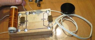
Assembled homemade PWM regulator board:
Source prom.st
The board is controlled manually and is carried out by a variable resistor or external voltage in the ranges:
0.45 V – device is turned off, duty cycle is 0%
0.5/3.5 V – smooth regulation, duty cycle from 0.1% to 99.9%
3.6 V – device on, duty cycle – 100%
The device operates at a constant voltage of 10 to 28 Volts.
The maximum voltage is limited by the maximum permissible voltage of the power switches, as well as the reverse voltage of the high-power diode in the load, when separate from the additional 15 V control power supply.
I advise you not to install a stabilizer if the voltage does not reach 15 Volts.
Instead, some kind of diode or regular jumper would be better.
If the voltage is from 15 to 28 Volts, then it is worth installing a linear (for example, 7815) or pulse stabilizer in the form of a ready-made module on the MP2307, and you must set the voltage on it to 15 Volts.
You can order them on the same Aliexpress.
If necessary, you can adjust the frequency with a continuously variable resistor.
To do this, you need to connect it to the board instead of a jumper.
Schmitt trigger converter
Those pulse stabilization devices that use a Schmitt trigger no longer have such a large number of components as in the previous type of device. Here the main element is the Schmitt trigger, which includes a comparator. The task of the comparator is to compare the voltage level at the output and its maximum permissible level.
Stabilizer with Schmitt trigger
When the output voltage has exceeded its maximum level, the trigger switches to the zero position and opens the switch. At this time, the inductor or capacitor is discharged. Of course, the characteristics of the electric current are constantly monitored by the aforementioned comparator.
And then, when the voltage drops below the required level, phase “0” changes to phase “1”. Next, the key closes and electric current flows into the integrator.
The advantage of such a pulse voltage stabilizer is that its circuit and design are quite simple. However, it cannot be applied in all cases.
It is worth noting that pulse stabilization devices can only work in certain directions. What we mean here is that they can be either purely downward or purely upward. There are also two more types of such devices, namely inverting and devices that can arbitrarily change the voltage.
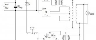
Homemade controller circuit
This circuit contains a minimum number of components in the circuits of the microcircuits:
Source usamodelkina.ru
The main PWM controller from 0% to 100%, which will control all the power in the load, is assembled on a TL494 chip.
With this switching option, the internal offset is compensated to create dead time.
When switching high currents, strong interference occurs.
An isolated +15 Volt -12 Volt power supply with additional overload protection is assembled on the NE555 chip.
The main task is to regulate secondary voltages by changing the frequency.
Depending on the load, it operates at a frequency in the range of 120-480 kHz.
In case of overload, the pulse width, as well as the frequency, is reduced.
If there is no load, the positive arm on the transformer tends to 25 volts, and the negative voltage decreases until it reaches zero.
If there is no load on the transformer, then either the driver is not connected or it is idle.
To reduce noise and load on the wires by cutting off reactive energy, you should install a freewheeling load diode in close proximity to the load itself.
In this case, you can use conductors whose cross-section is smaller than those used when installing the diode away from the load.
Source ytimg.com
PWM – pulse width modulation
PWM is predominantly used to generate a sinusoidal signal. PWM is often used to control the operation of an inverter converter. The inverter is designed to convert DC energy into AC energy.
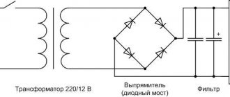
Let's consider the simplest voltage inverter circuit.
At one point in time, a pair of transistors VT1 and VT3 opens. A path is created for the flow of current from the battery GB through the active-inductive load RнLн. At the next moment, VT1 and VT3 are locked, and diagonally opposite transistors VT2 and VT4 are open. Now current flows from the battery through RnLn in the opposite direction. Thus, the current across the load changes its direction and is therefore variable. As you can see, the load current is not sinusoidal. Therefore, PWM is used to obtain a sinusoidal current waveform.
There are several types of PWM: unipolar, bipolar, one-way, two-way. Here we will not dwell on each specific type, but will consider the general approach.
A sinusoid is used as a modulating signal, and a triangular signal is used as a reference signal. As a result of comparing these signals, the durations of pulses and pauses are formed (lower graph), which control the operation of transistors VT1...VT4. Please note that the voltage amplitude across the load is always equal to the amplitude of the power supply. The pulse repetition period also remains unchanged. Only the width of the opening pulse changes. Therefore, when a load is connected, the current flowing through it will have a sinusoidal shape (shown by the dotted line in the lower graph).
So, the main difference between WIDTH and PWM is that with pulse-width control, the pulse and pause times remain constant. And with pulse-width modulation, the durations of pulses and pauses change, which makes it possible to realize an output signal of a given shape.
Controller testing
One way to use this controller is to smoothly control the speed of an electric motor.
In this case, you don’t have to remove the standard discrete speed control circuit - it remains, is not disturbed and continues to work.
The circuit is connected with only three wires: plus at 12 volts, ground and the wire of the electric motor itself.
The board can also be used to replace the switch and quenching resistor in the original circuit.
First of all, when testing, make sure that all parts are in place and securely fastened.
Next, the manufactured PWM controller for the electric bicycle motor must be simultaneously connected to both the battery and the bicycle motor, which will set it in motion.
Use a set of lithium battery cells with a nominal voltage of 80 Volts (these batteries are used in electric bicycles).
By turning the potentiometer clockwise, your bike's engine will gradually begin to rotate, and its speed will increase in proportion to the rotation of the handle.
If everything is in order, then your homemade PWM controller is assembled correctly.
Source ytimg.com
I recommend the following video, in which the author makes a PWM regulator with his own hands:
Pulse width control WID
In Western literature, there is practically no distinction between the concepts of pulse-width regulation of WID and pulse-width modulation of PWM. However, we still have a difference between them.
Nowadays, many microcircuits, especially those used in DC-DC converters, implement the WID principle. But at the same time they are called PWM controllers. Therefore, now there is practically no difference in name between these two methods.
In any case, to form a certain pulse duration supplied to the base of the transistor and opening the latter, reference and setting voltage sources, as well as a comparator, are used. Let's consider a simplified circuit in which the battery GB supplies the consumer Rн in a pulsed manner through the transistor VT. I’ll say right away that in this circuit I specifically did not use such elements necessary for the operation of the circuit: a capacitor, an inductor and a diode. This is done to simplify the understanding of the operation of the PWM, and not the entire converter.
To put it simply, a comparator has three terminals: two inputs and one output. The comparator works as follows. If the voltage value at the “+” input pin (non-inverting input) is higher than at the “-” input (inverting input), then the output of the comparator will be a high level signal. Otherwise - low level.
In our case, it is the high level signal that opens the transistor VT. Let's consider how the required pulse time duration ti is formed. To do this, we will use the following graph.
With WID, a sawtooth signal of a given frequency is supplied to one input of the comparator. It is also called the support. The second input is supplied with a reference voltage, which is compared with the reference voltage. As a result of the comparison, a pulse of the appropriate duration is formed at the output of the comparator.
Recommended reading: Running fire with controlled speed
If there is a reference signal at the non-inverting input of the comparator, then there will be a pause first, and then a pulse. If a master signal is applied to the non-inverting input, there will first be a pulse, then a pause.
Thus, by changing the value of the specified signal, you can change the duty cycle, and, accordingly, the average voltage at the load.
They strive to make the frequency of the reference signal maximum in order to reduce the parameters of the chokes and capacitors (not shown in the diagram). The latter leads to a reduction in the weight and dimensions of the switching power supply.
As a result…
Do-it-yourself PWM controller is ready. Assembling it will not be difficult for anyone who has at least a little knowledge of radio engineering. I built my controller for use in an electric bike motor, but it can be used for more than just motors. This is a universal device - suitable for adjusting the brightness of the lamps, the speed of the motor, and the current in the charger.
Question
Write in the comments how reliable do you think PWM controllers from Aliexpress are?
Reasons and applications of PWM
The principle of pulse width modulation is used in speed controllers of powerful asynchronous motors. In this case, a modulating signal of adjustable frequency (single-phase or three-phase) is generated by a low-power sine wave generator and superimposed on the carrier in an analogue way. The output produces a PWM signal, which is supplied to the switches of the required power. Then you can pass the resulting sequence of pulses through a low-pass filter, for example through a simple RC chain, and isolate the original sinusoid. Or you can do without it - filtration will occur naturally due to the inertia of the engine. Obviously, the higher the carrier frequency, the closer the output waveform is to the original sine wave.
We recommend reading: Questions about programming microcontrollers
A natural question arises: why can’t the generator signal be amplified immediately, for example, by using powerful transistors? Because the regulating element operating in linear mode will redistribute power between the load and the switch. In this case, significant power is wasted on the key element. If a powerful control element operates in switching mode (thyristor, triac, RGBT transistor), then the power is distributed over time. Losses will be much lower, and efficiency will be much higher.
In digital technology there is no special alternative to pulse width control. The amplitude of the signal there is constant; the voltage and current can only be changed by modulating the carrier along the pulse width and subsequently averaging it. Therefore, PWM is used to regulate voltage and current on those objects that can average a pulse signal. Averaging occurs in different ways:
- Due to load inertia. Thus, the thermal inertia of thermoelectric heaters and incandescent lamps allows the controlled objects not to noticeably cool down in pauses between pulses.
- Due to the inertia of perception. The LED manages to go out from pulse to pulse, but the human eye does not notice this and perceives it as a constant glow with varying intensities. This principle is used to control the brightness of LED monitors. But imperceptible blinking with a frequency of several hundred hertz is still present and causes eye fatigue.
- Due to mechanical inertia. This property is used when controlling brushed DC motors. If the control frequency is correctly selected, the motor does not have time to slow down during dead pauses.
Therefore, PWM is used where the average value of voltage or current plays a decisive role. In addition to the common cases mentioned, the PWM method is used to regulate the average current in welding machines and battery chargers, etc.
If natural averaging is not possible, in many cases this role can be taken over by the already mentioned low-pass filter (LPF) in the form of an RC chain. For practical purposes, this is enough, but you need to understand that it is impossible to isolate the original signal from PWM using a low-pass filter without distortion. After all, the PWM spectrum contains an infinitely large number of harmonics, which will inevitably fall into the filter passband. Therefore, you should not create illusions about the shape of the reconstructed sinusoid.
PWM control of an RGB LED is very effective and efficient. This device has three pn junctions - red, blue, green. By changing the brightness of each channel separately, you can get almost any LED color (with the exception of pure white). The possibilities for creating lighting effects using PWM are endless.
The most common application of a pulse-width modulated digital signal is to regulate the average current or voltage flowing through a load. But non-standard use of this type of modulation is also possible. It all depends on the imagination of the developer.
How to make it yourself?
There are various options for adjustment schemes. Let us present one of them in more detail.
Here is how it works:
Initially, this device was developed to adjust the commutator motor in electric vehicles. We were talking about one where the supply voltage is 24 V, but this design is also applicable to other engines.
The weak point of the circuit, which was identified during testing of its operation, is its poor suitability at very high current values. This is due to some slowdown in the operation of the transistor elements of the circuit.
It is recommended that the current be no more than 70 A. There is no current or temperature protection in this circuit, so it is recommended to build in an ammeter and monitor the current visually. The switching frequency will be 5 kHz, it is determined by capacitor C2 with a capacity of 20 nf.
As the current changes, this frequency can change between 3 kHz and 5 kHz. Variable resistor R2 is used to regulate the current. When using an electric motor at home, it is recommended to use a standard type regulator.
At the same time, it is recommended to select the value of R1 in such a way as to correctly configure the operation of the regulator. From the output of the microcircuit, the control pulse goes to a push-pull amplifier using transistors KT815 and KT816, and then goes to the transistors.
The printed circuit board has a size of 50 by 50 mm and is made of single-sided fiberglass:
This diagram additionally shows 2 45 ohm resistors. This is done for the possible connection of a regular computer fan to cool the device. When using an electric motor as a load, it is necessary to block the circuit with a blocking (damper) diode, which in its characteristics corresponds to twice the load current and twice the supply voltage.
Operating the device in the absence of such a diode may lead to failure due to possible overheating. In this case, the diode will need to be placed on the heat sink. To do this, you can use a metal plate that has an area of 30 cm2.
We recommend reading: I love making gifts with my own hands
Regulating switches work in such a way that the power losses on them are quite small. In the original design, a standard computer fan was used. To connect it, a limiting resistance of 100 Ohms and a supply voltage of 24 V were used.
The assembled device looks like this:
When manufacturing a power unit (in the lower figure), the wires must be connected in such a way that there is a minimum of bending of those conductors through which large currents pass. We see that the manufacture of such a device requires certain professional knowledge and skills. Perhaps in some cases it makes sense to use a purchased device.