Finding artifacts underground is a fairly popular activity. For some, this is a profession, others are simply interested in archaeology. There are numerous groups of treasure hunters: both romantics and pragmatic treasure hunters. All these people are united by one passion: searching for metal objects hidden at various depths.
Just because you have an accurate map showing where the treasure is buried, or plans for fighting during the war, this does not guarantee success. You can shovel tons of soil, and the desired item will calmly lie a couple of meters from the active search site.
To search for gold and less valuable metals, you will need a metal detector that you can make yourself.
Important information: The use of such devices is not prohibited by law. However, there are penalties for the consequences of such a search regarding excavations, as well as the recovery of discovered objects.
We won’t go into details; that’s the topic of another article. Simply put: if you find a gold ring on the beach, or a handful of Soviet coins in the forest, there will be no problems associated with the use of electronic search tools.
But for recovered bronze spoons that are 100 years old or older, you can get a real sentence or a large fine.
Nevertheless, devices for searching for metal objects in the depths of the earth are freely sold, and those who want to save money can make a metal detector with their own hands at home.
How does a metal detector work?
A metal detector, or metal detector, is an electronic device consisting of a primary sensor (coil with winding) and a secondary unit. Metal detection devices are divided into several types:
- "reception and transmission";
- induction;
- pulse;
- generator
Metal detector device
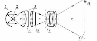
Devices in the mid-price category are mainly of the “receive-transmit” type. The operating principle of such metal detectors is based on the transmission and reception of electromagnetic waves. The main elements of a device of this type are two coils: one is transmitting, and the second is receiving. The first coil transmits electromagnetic waves that freely pass through a neutral medium and which, when colliding with metal objects, are reflected and transmitted to the receiving device. After the reflected signal hits the second coil, the operator is informed by a buzzer that the target has been found.
The principle of operation of the metal detector
An induction-type metal detector operates on the same principle as transmit-receive devices. The main difference between them is the number of coils with winding. An induction metal detector has one coil that sends and receives a signal simultaneously. Pulse devices are insensitive to the concentration of salts in the soil and include in their design a coil, the electromagnetic field of which creates eddy currents on the metal surface that are captured by the detector. This principle of operation reduces the possibility of discrimination, which can complicate the search.
Operating principle of a pulse metal detector
Generator-type metal detectors come in different types, but they are all built on the basis of an LC generator. They have a low level of sensitivity and are generally designed to find only one type of metal. Metal detectors can also be divided into three
- common use;
- middle class;
- professional equipment.
A simple metal detector with two transistors
Rice. 7. Scheme of a simple metal detector using silicon and field-effect transistors.
The diagram of a simple metal detector is shown in Fig. 7. The device uses a low-frequency LC generator, the frequency of which depends on the inductance of the search coil L1. In the presence of a metal object, the generation frequency changes, which can be heard using the BF1 telephone capsule. The sensitivity of such a scheme is low, because It is quite difficult to detect small changes in frequency by ear.
How to assemble a “Pirate” metal detector with your own hands: detailed instructions
The “Pirate” models are quite expensive, which is determined by the device’s ability to detect objects at a depth of 0.2 m (small) and 1.5 m (large). You should consider the design features and settings for metal detecting.
Materials needed to assemble a powerful metal detector with your own hands
The Pirate metal detector is considered a pulse device. To make the device, you will need to buy:
- IC KR 1006VI1 to create a transmitting unit;
- transistor IRF 740;
- IC K 157UD2 and transistor BC 547 to assemble the receiving unit;
- NPN transistors;
- PEV 0.5 wire to create a coil;
- materials to make the body, etc.;
- a plate covered with copper sheet to make a printed circuit board;
- the wire;
- electrical tape;
- soldering iron;
- scalpel;
- screwdrivers;
- pliers;
- different types of fasteners.
Assembly tools PHOTO: youtube.com
DIY metal detector circuits
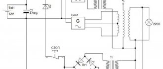
The standard circuit of the “Pirate” metal detector is based on the NE555 chip. The operation of the device will depend on the comparator: 1 output is connected to the IC generator, 2 to the coil, and the output to the speaker. When detecting metal objects, a pulse from the coil will go to the comparator and then to the speaker.
The board is placed in a junction box, which can be purchased at electronics stores PHOTO: youtube.com
DIY printed circuit board
If spare parts are purchased, there is a diagram, then you need to put everything together. To place the radio components, a printed circuit board is used, which you can easily make yourself. You will need sheet getinax covered with technical copper foil.
The selected pattern is transferred to the workpiece, the tracks that connect the parts are marked, holes are drilled PHOTO: youtube.com
The tracks are coated with a protective varnish, and after drying, the board is lowered into ferric chloride for etching.
When the product is ready, it is possible to install and solder the radio components. The next stage will be checking the circuit using measuring instruments.
DIY coil for metal detector
The Pirate metal detector is considered a pulse device, so accuracy during coil assembly does not play a key role. For the base you need a ring with a diameter of 20 cm, on which 25 turns of wire are wound. To increase the depth of metal detection, the coil frame should be approximately 26-27 cm, and the number of turns should be 20-22.
Then the mandrel with the wire is thoroughly wrapped with insulation. The finished coil is placed inside a dielectric housing. You can use materials that fit the dimensions of the housing of faulty household appliances. This will make it possible to protect the coil from damage when working with the device. The ends of the winding are soldered to a stranded wire with a diameter of 0.6 mm.
Making a coil PHOTO: youtube.com
Watch this video on YouTube
How to assemble and set up a metal detector with your own hands
Each unit of the device is fixed to the metal detector rod. When the circuit is properly assembled, there is no need to adjust the device, since it immediately has high sensitivity.
More fine tuning is done using variable resistors R13. The required functioning of the metal detector is ensured with the regulator in the middle position.
Watch this video on YouTube
How to make an underwater metal detector with your own hands
In some cases, searches are moved from the ground to water. There are, of course, special devices for functioning under water. And, in principle, you can make a deep metal detector yourself. It is necessary to take the simplest homemade device and place each unit in a hermetically sealed housing. In addition, it is necessary to slightly modify the device and install LED indicators instead of sound signals.
Underwater metal detector PHOTO: youtube.com
Watch this video on YouTube
Household metal detector
A household metal detector (HIM) (Fig. 15), produced earlier (Moscow), allows you to detect small metal objects at a distance of up to 45 mm. The winding data of its inductors are unknown, however, when repeating the circuit, you can rely on the data given for devices of similar purposes (Fig. 13 and 14).
Rice. 15. Scheme of a household metal detector.
Literature: Shustov M.A. Practical circuit design (Book 1), 2003
Main settings
Search method
Induction metal detectors (MD) consist of a transceiver inductor.
When the emitted signal hits a metal object, it is reflected back and recorded by the receiver. These devices are quite simple to make with your own hands, but their sensitivity greatly depends on the type of soil and the quality of the coil.
Pulsed MDs excite eddy currents in the search zone and measure the secondary damped electromagnetic field. The sensitivity of these devices is higher and does not depend on the type of soil. However, they consume a lot of electricity, which does not allow them to work in autonomous mode for a long time.
Phase-sensitive MDs can be:
- Impulse. The receiver and transmitter here are one and the same element. It records the phase shift of the signal reflected from the metal. The increase in phase shift causes clicks in the headphones: the closer the MD is to the metal, the more frequent they become, eventually merging into a single sound. The work of the popular metal detector “Pirate” is based on this method.
- Double-circuit. Consist of 2 symmetrical generators and 2 detectors. A metal object disrupts the synchronization of the generators, and the same clicks occur, merging into a continuous tone.
- Parametric MDs have neither a receive nor a transmit coil, making them simple, cheap, and popular for DIY assembly. An LC generator creates an electromagnetic field at audio frequency. Any metal near the metal detector changes the parameters of the coil detector, which affects the frequency and amplitude of the generated signals. The diagram of such devices is easy to find. However, their sensitivity is low and does not allow complex searches. Parametric MDs are divided into:
- Frequency MD. They emit multi-frequency signals. When approaching metals, the device detects a change in frequency.
- Metal detectors that record changes in the quality factor of the circuit. When the distance between the device and the metal decreases, the device records this.
Detection depth
The detection depth depends on the coil diameter, electronic circuit and operating frequency. The larger the diameter of the wire coil, the more powerful the emitted electromagnetic field and the lower its frequency, the deeper the detection zone of a DIY metal detector.
However, as the search depth increases, the sensitivity of the metal detector to small objects deteriorates, and its selective capabilities also decrease. Energy consumption and weight of the device increase, which makes it difficult to hold the metal detector in your hands for a long time.
Operating frequency
Based on the frequency of operation, MDs are divided into:
- High frequency. They operate at frequencies of several hundred kHz. They are used in devices designed to search for gold, as they have excellent discrimination. But they sharply lose sensitivity on wet and magnetic soils, as well as at a depth of more than 40 cm.
- Mid-frequency. Operating frequency up to several tens of kHz. The requirements for the quality of the coil are lower, good sensitivity. Detection depth is up to 1.5 meters, provided that the soil is dry and low-mineralized.
- Low frequency. They operate at frequencies from hundreds of Hz to several kHz. These are deep metal detectors that detect objects up to 5 meters underground. They are easy to make with your own hands. Disadvantages: low sensitivity and high power consumption. Suitable as magnetic detectors, as well as for searching for large objects made of ferrous metal (fittings, wiring).
- Ultra-low frequency. They are not suitable for amateur searches, as they have high power consumption and large dimensions, and special programs are required for signal processing. Operating frequency up to several hundred Hz. These metal detectors cannot be held by hand, so they are mounted on a car.
Simple metal detector transmit-receive
B. SOLONENKO, Genichesk, Kherson region, Ukraine
It would not be an exaggeration to say that metal detectors invariably attract the attention of radio amateurs. Quite a few such devices were published in the Radio magazine. Today we offer readers a description of another design created in the radio design circle of the Technical Station for Young Technicians (see the article about it in Radio, 2005, No. 4, 5). The circle members were given the task: to develop an easy-to-manufacture device based on an accessible element base, for the setup of which one multimeter is enough. How successful the guys were is for you, the readers, to judge.
The proposed metal detector operates on the “transmission-reception” principle. A multivibrator is used as a transmitter, and an audio frequency amplifier (34) is used as a receiver. Coils of the same size and winding data are connected to the output of the first of these devices and the input of the second,
In order for a system of such a transmitter and receiver to become a metal detector, their coils must be positioned so that in the absence of foreign metal objects, there is practically no communication between them, i.e., the transmitter signal does not go directly to the receiver. As is known, the inductive coupling between coils is minimal if their axes are mutually perpendicular. If the transmitter and receiver coils are positioned this way, the transmitter signal will not be heard in the receiver. When a metal object appears in the vicinity of this balanced system, under the influence of the alternating magnetic field of the transmitting coil, so-called eddy currents arise and, as a result, its own magnetic field, which induces an alternating EMF in the receiving coil. The signal received by the receiver is converted by phones into sound. Its volume depends on the size of the object and the distance to it.
Technical characteristics of the metal detector
: operating frequency - about 2 kHz;
detection depth of a coin with a diameter of 25 mm is about 9 cm; iron and aluminum seaming caps - 23 and 25 cm, respectively; steel and aluminum sheets measuring 200×300 mm - 40 and 45 cm; sewer hatch - 60 cm. Fig. 1
Transmitter
. The transmitter circuit is shown in Fig. 1. As mentioned, this is a symmetrical multivibrator based on transistors VT1, VT2. The frequency of the oscillations it generates is determined by the capacitance of capacitors CI, C2 and the resistance of resistors R2, R3. Signal 34 from the collector load of transistor VT2 - resistor R4 - is supplied through a separating capacitor SZ to coil L1, which converts electrical oscillations into an alternating magnetic field of the AF.
Fig.2
Receiver
is a three-stage amplifier 34, made according to the circuit shown in Fig. 2. At its input the same coil L1 is connected as in the transmitter. The amplifier output is loaded with telephones BF1.1, BF1.2 connected in series.
Fig.3
The alternating magnetic field of the transmitter, induced in a metal object, acts on the receiver coil, as a result of which an electric current with a frequency of about 2 kHz appears in it. Through the isolation capacitor C1, the signal is supplied to the input of the first stage of the amplifier, made on transistor VT1. The amplified signal from its load - resistor R2 - is fed through the separating capacitor SZ to the input of the second stage assembled on transistor VT2. The signal from its collector through capacitor C5 is supplied to the input of the third stage - the emitter follower on transistor VT3. It amplifies the current signal and allows you to connect low-impedance phones as a load.
To reduce the influence of ambient temperature on the stability of the amplifier, negative DC voltage feedback is introduced into the first and second stages by connecting resistor R1 between the collector and base of transistor VT1 and resistor R3 between the collector and base of VT2. Reducing the gain at frequencies below 2 kHz was achieved by appropriately selecting the capacitance of the coupling capacitors C1, SZ; at frequencies above this frequency, by introducing into the first and second stages frequency-dependent negative feedback on alternating voltage through capacitors C2 and C4. These measures made it possible to increase the receiver's noise immunity. Capacitor C6 prevents the amplifier from self-excitation when the internal resistance of the battery increases as it discharges.
Fig.4
Details and design
. The parts of the transmitter and receiver are placed on printed circuit boards made by cutting insulating tracks on blanks made of one-sided foil fiberglass. A drawing of the transmitter board is shown in Fig. 3, receiver - in Fig. 4. The boards are designed to use MLT resistors with a power of 0.125 or 0.25 W and capacitors K73-5 (C2, C4 in the receiver) and K73-17 others. The oxide capacitor C6 in the receiver is K50-35 or similar foreign-made. Instead of those indicated in the diagram, you can use any other transistors of the KT503 series in the transmitter, and transistors of the KT315 series with any letter index or KT3102 series with indexes AB in the receiver. The use of the latter is preferable, since they have a lower noise figure, and the signal from small objects will be less masked by the noise of the amplifier. SA1 switches can be of any design, but preferably smaller in size. Phones BF1, BF2 are small-sized in-ear phones, for example, from an audio player.
The receiver and transmitter coils, as already mentioned, are the same. They are made like this. At the corners of a rectangle measuring 115x75 mm, four nails with a diameter of 2...2.5 and a length of 50...60 mm are driven into the board, after having previously put on them polyvinyl chloride or polyethylene tubes 30...40 mm long. 300 turns of PEV-2 wire with a diameter of 0.12...0.14 mm are wound onto the nails insulated in this way. Upon completion of winding, the coils are wrapped around the entire perimeter with a narrow strip of insulating tape, after which any two adjacent nails are bent towards the center of the rectangle and the coil is removed.
Polystyrene button boxes (internal dimensions - 120x80 mm) were used as receiver and transmitter housings. The battery compartments, racks for printed circuit boards and coil mounting elements are made of the same material and glued to the housings with R-647 solvent (R-650 can also be used). The arrangement of parts in the transmitter housing is shown in Fig. 5, the receiver parts are arranged similarly.
Fig.5
All metal structural elements located inside the receiver and transmitter coils (battery, circuit board with parts, power switch) affect their magnetic field. To exclude possible changes in their position during operation, they must all be securely fastened. This is especially true for the Krona battery as a replaceable structural element.
Setting up
. To check the operation of the transmitter, connect telephones instead of the L1 coil and make sure that sound is heard in the telephones when the power is turned on. Then, having connected the coil in place, they control the current consumed by the transmitter; it should be within 5...7 mA.
The receiver is set up with the input short-circuited. By selecting resistor R1 in the first stage and R3 in the second, a voltage equal to approximately half the supply voltage is set on the collectors of transistors VT1 and VT2, respectively. Then, by selecting resistor R5, the collector current of transistor VT3 becomes equal to 5...7 mA. After this, opening the input, connect the receiver coil L1 to it and, receiving the transmitter signal at a distance of about 1 m, make sure that the system as a whole is working.
Before assembling the units into a single structure, it makes sense to conduct several experiments. Having installed the transmitter and receiver on the table vertically at a distance of 1 m (so that the axes of the coils seem to continue one another) and monitoring the signal level in the phones, slowly rotate the receiver around the vertical axis to a position in which the planes of the coils are perpendicular to one another. In this case, the signal will first slowly decrease, then disappear completely, and with further rotation it will begin to increase. Carry out the experiment several times so that when assembling and setting up the metal detector, it is easy to determine the minimum signal in the receiver.
Fig.6
Then, on a table that does not contain metal structural elements, place the transmitter vertically, and at a distance of 10 cm from it, place the receiver horizontally on a stand (one or more books) so that the plane of the receiver coil is perpendicular to the plane of the transmitter coil and is slightly higher in height. below its center. While monitoring the signal strength of the phones, lift the side of the receiver facing the transmitter until the signal drops. By selecting spacers between the receiver and the stand, find its position at which the slightest movement of the spacer made from a paper postcard allows you to set the minimum signal in the receiver, which corresponds to the maximum sensitivity of the metal detector.
By introducing tin and aluminum caps alternately into the coverage area of the metal detector model, make sure that the zone of maximum sensitivity of the metal detector is under and above the receiver coil (the magnetic fields of the receiver and transmitter coils are symmetrical). Please note that the metal detector reacts differently to covers of the same size made of different metals.
Fig.7
If, with minimal coupling of the coils, the signal is slightly audible and, when the cap is inserted on one side, first decreases until it completely disappears, and then begins to increase, and when it is inserted from the other side, it increases without a dip, then this indicates either an inaccurate setting of the minimum, or distortion of the magnetic field. fields of the receiver or transmitter coil. At the same time, this fact suggests that by introducing an additional metal object, you can adjust the system until the signal completely disappears at a minimum, i.e., achieve maximum sensitivity of the device. If, when the sealing cap is inserted, the signal disappears completely from a distance of 15...20 cm, then by introducing a smaller object into the metal detector field, the same effect can be achieved by placing it on the receiver or transmitter body. In the author’s version, such an object turned out to be a coin with a diameter of 25 mm made of yellow metal (a similar effect will be achieved by introducing an aluminum plate of similar size). There were three places in which the coin performed its assigned task: below, under the transmitter, under the receiver in the area of the battery, and on the handle between the receiver and transmitter.
Assembly
. The design of the author's version of the device is shown in a simplified form in Fig. 6, and the appearance is in Fig. 7. Carrier rail 2 (see Fig. 6) and handle 3 are made of wood. The upper part of the handle is covered with plastic for ease of use, and the lower part is inserted into a pre-made hole in the rail and secured with glue. After assembly, the wooden part of the handle 3 and the supporting rail 2 are coated with varnish to protect them from moisture. At the top of the handle there is a telephone socket 4, which is connected to the receiver by wires twisted in pairs.
During assembly, the transmitter 1 is rigidly fixed to the carrier rail 2 in such a way that the receiver 7, located at its other end, is slightly below the line corresponding to the minimum of the received signal. Then select the thickness of the gasket 5 (from any insulating material) until the minimum of the received signal is easily established by moving the adjusting plate 6. After this, the receiver 7 is fixed to the carrier rail 2 with two screws. The screw at the edge of the support rail 2 is screwed in all the way, and the second one (approximately in the middle of the lower wall of the housing) is not screwed in 1...2 mm. This prevents the receiver from moving in a horizontal plane and at the same time allows you to slide the adjustment plate 6 under its body, raising the edge of the receiver. By moving it in this way in the vertical plane, we achieve a minimum of the received signal. After final assembly, the location of the compensating item is specified and it is glued.
Metal detector circuit CHANCE
And also a diagram of the metal detector control buttons
The circuit of this metal detector has an average level of complexity. Assembling it will require some experience. In its circuitry, the CHANCE metal detector contains a microcontroller, so for its successful assembly of baths you will need an in-circuit programmer. Also in the metal detector circuit there are a number of quite expensive components: a screen, a processor, and an ADC
Particular attention should be paid to the MCP3201 ADC; only after purchasing it can you proceed to further assembly of the metal detector. Since it is very difficult to find
In operation, CHANCE showed itself to be a simple and reliable metal detector, but with discrimination, everything is not very rosy. In reality, the device only filters out small iron debris and small nails, but beer caps already cause discrimination difficulties. Also CHANCE, like other pulse metal detectors, does not see gold chains well.
Do-it-yourself assembly of the CHANCE metal detector.
The process of assembling the CHANCE metal detector must begin with the manufacture of a printed circuit board. Boards wired by DexAlex have proven themselves to be quite good. Download a drawing of a printed circuit board in Sprint Layot format and other materials and recommendations for self-assembly of the CHANCE metal detector from DexAlex. Drawing of the printed circuit board and description of the assembly of the CHANCE metal detector. Also in the archive you will find a list of parts for assembling the CHANCE metal detector.
Assembled metal detector board chance
After manufacturing and soldering the board, it is necessary to flash the microcontroller. The latest firmware version is 1.2.1. At the end of the article you can download an archive with all firmware versions.
To flash the microcontroller firmware, we arrange the configuration bits as in the figure below.
After this, we connect the power to the metal detector and admire its work. True, he doesn’t see metal yet. We still need to make a coil.
And this is what the assembled block looks like:
Video of the CHANCE metal detector launching:
https://youtube.com/watch?v=q_PTa7k1dFE
Chance can work with coils from any pulse metal detectors, but for good metal discrimination performance, only coils with low parasitic capacitance are suitable. Therefore, it is better to make a coil for a metal detector according to the diagram below:
To wind the coil, you can use winding enamel wire with diameters of 0.67 - 0.85 mm.
After connecting the coil, you can already fully test the metal detector. But to fully work with your metal detector, you should put it in the case and make a rod for it. You can see the assembled metal detector in the top photo.
The Chance metal detector has proven itself well and has good reviews. And some radio amateurs even set up small-scale production of it.
The only video test of the “CHANCE” metal detector found on the Internet
Website address of the developer of this metal detector. https://fandy.hut2.ru/Chance.htm
All firmware versions for the CHANCE metal detector - Firmware
Board, circuit, printed circuit board and other materials for the CHANCE metal detector from DexAlex - Chance layout from DesAlex
You can read many reviews about the work of the CHANCE metal detector here: https://www.md4u.ru/viewtopic.php?f=5&t=4246
Features of deep metal detectors
A deep metal detector is attractive because it can detect objects where other devices are powerless. A good deep metal detector, made by yourself, looks to a depth of 6 meters, and is not hindered by roots, voids or other obstacles. One caveat - with its help you can only detect large objects, and this is understandable, because for the sake of a couple of coins you will not dig a six-meter hole.
And again we return to the same universal model of the “Pirate” detector. It turns out that you can make an in-depth device based on it, and it’s not at all difficult. The modification process is described in this video.
As you can see, nothing is impossible! If you have a passion, try and experiment. Perhaps, somewhere, countless treasures await you that can radically change your life. If you have experience in assembling such a device and using it, share it in the comments, we will be very grateful to you!
DIY metal detector
DIY metal detector
Despite the fact that the metal detecting season is coming to an end, as well as the weather, those who study and work interfere with this. But despite this, people continue to be interested in assembling a metal detector with their own hands.
In this article I would like to post a diagram of a metal detector called Terminator-3. It has justified itself both by frequent assembly by radio amateurs and by good search characteristics, as discussed further in the sequel. The design of this metal detector, developed by Yatogan (Yatogan, MD4U forum) and Radiogubitel (MD4U forum), has circuitry similar to devices from the famous Tesoro company, but is much easier to set up. The impetus for the spread of this development was the printed circuit boards (with modifications and improvements) of another homemade product - A2111105 (MD4U forum, Soldering Iron forum).
Idea No. 2 – Use a radio receiver
Another version of a simple, but no less functional metal detector can be assembled using the following available tools:
- CD box;
- a radio receiver that operates in the AM range;
- calculator;
- Double-sided tape.
A detailed description of how to quickly, simply and easily make a metal detector from a radio:
- We attach the calculator and receiver to the inner walls of the box using double-sided tape.
- We turn on both devices, and set the radio receiver to the maximum frequency (at the same time, so that there is no noise from the radio stations).
- Close the box and slowly open it until a more or less clear sound appears. In this position, the homemade metal detector is set to search.
As you can see, you can make a homemade product in no longer than 5 minutes. This option is suitable for electric teapots, because...
here you can do without drawings and you don’t need to connect any microcircuits. You can additionally make a handle to make the process easier. With the help of such a homemade product, you can check the wall before installing the socket, otherwise, when you gouge, you will end up with old wiring!
An object lesson on how to create a good metal detector from a radio. These are, in fact, the most reasonable methods to use to make a metal detector at home with your own hands. As for soldering a more complex model, such as a butterfly or terminator, that’s up to you. On the one hand, you can save at least 5,000 rubles (the cost of a budget device model), but on the other hand, reviews from many DIY enthusiasts indicate that such devices rarely work as desired.
Also read: Video instructions for assembling a metal detector from disksObject lesson on creating a metal detector from a radio
None Content.
- 1. Idea No. 1 – Use discs!
- 2. Idea No. 2 – Use a radio receiver
Today, there are many different ideas that allow you to make a metal detector with your own hands at home. Some of them require certain skills in working with radio and electrical devices, while some do not require any knowledge in this area to create. Next, readers of Self Electrician will be provided with several interesting and at the same time simple schemes for creating a homemade metal detector!
[custom_ads_shortcode2]
How to make a Terminator 3 metal detector with your own hands: detailed instructions
The Terminator 3 model has long been popular among radio amateurs, and over the many years of its existence the device has received many improvements. We offer step-by-step instructions on how to make a metal detector yourself at home. The device has low power consumption, can be configured to search for certain types of metal, and has good depth characteristics.
Appearance of the electronic control unit
Tools
Before making a homemade metal detector, you need to prepare the following tools:
- soldering iron or soldering station;
- solder, tin, rosin;
- pliers, round nose pliers, side cutters;
- Screwdriver Set;
- hacksaw for metal;
- oscillography and other instrumentation.
Amateur radio tool kit
Diagram, selection of parts and circuit board
To manufacture the control unit, it is necessary to make a circuit board on which all the necessary radio components will be placed. The circuit presented below must be transferred to a getinax plate coated with copper foil and a circuit board must be made in the same way as described above in the article for the Pirate metal detector. The size of the circuit should be within 104x66 mm, and the board blank should be 10 mm larger on each side.
Schematic diagram of the Terminator 3 metal detectorList of required radio componentsPrinted circuit board of the metal detector
We will describe in detail how to prepare a printed circuit board for a metal detector in step-by-step instructions:
Metal detector coil
This is, in fact, the most sensitive part of the device. She is responsible for scanning the space underground. Let's look at the steps to create a simple coil for a metal detector:
| Illustration | Process description |
| On a piece of plywood we draw two circles corresponding to the diameters of the coils - internal and external. We drive nails around the perimeter of the circle. The diameter of the outer winding TX should be within 200mm. The coil is made from two folded wires. We wind 30 turns on the nails. | |
| We tie the winding around the circumference with threads. We take out the nails, cover the resulting coil with varnish, and after it dries, wrap it with electrical tape and foil. In exactly the same way we make the internal winding RX, which is half the size of TX and contains 48 turns of wire. | |
| We place the coils in the housing and wire the wires that will be connected to the control unit. | |
| This is what the finished metal detector frame will look like. |
Homemade metal detector: detailed description of assembly diagram and setup
We discussed in detail the stages of assembling the board and the main elements of the metal detector earlier, now we are faced with the very last and most important steps: assembling the case and setting up the device.
This video will help you set up your metal detector.
P O P U L A R N O E:
- List of abbreviations in TV descriptions.
- Simple DIY metal detector
- Learning to type quickly on the keyboard
Abbreviations for TV components are often found in diagrams and descriptions. The table below will help a novice radio amateur understand all the abbreviations of the circuits of domestic and imported televisions. Read more...
Metal detector for synchronization failures “Butterfly”
For beginners, a simple metal detector circuit with two coils is based on the principle of disrupting the synchronization of these same generators. There are many different metal detector circuits on the Internet, but it is quite difficult for a novice radio amateur to correctly configure and adjust the assembled circuit without an oscilloscope. We propose to assemble a simple metal detector with your own hands with simple settings. Read more...
Now computers have become a part of our lives. When working on a computer you have to type often. Can you type quickly on a keyboard?
Do you search for letters and type with one finger? A small free program called Rapid Typing Tutor will help you master the computer keyboard and teach you how to type quickly in a fun and relaxed way.
Read more...
SHARE WITH YOUR FRIENDS:
Popularity: 24,999 views.
www.mastervintik.ru Many treasure hunting enthusiasts, and simply people trying to save money, are wondering how to make a metal detector with their own hands. We will immediately note that using available materials you can make an amateur metal detector device whose characteristics are much inferior to professional devices. Even if something comes close to them in terms of search level, you need to at least have a good knowledge of radio engineering, understand circuitry and spend much more time and money than we suggest in this article. We provide instructions on how to make the simplest metal detector at home with your own hands. Therefore, you should not expect anything more from it than identifying small metal objects on (or) shallow in the ground. A homemade metal detector is also suitable as a device for entertaining children, detecting nuts, nails, and coins. For more serious purposes, you should buy a professional-type metal detector. Before moving on to any actions to make a metal detector with your own hands, you need to understand what it is and on what principles it works.
The vast majority of metal detectors, regardless of type, have a similar design. Therefore, the methods we proposed for creating a metal detector with your own hands differ only partly. A professional metal detector consists of several parts: a handle that is adapted for comfortable carrying and detection, the detector itself - often it is a coil, and a control box that includes a battery, microspeaker, board or microprocessor.
The principle of operation of a metal detector Metal detectors of any complexity for detecting metal work on the effect of changing the magnetic field emitted by the detector coil. The magnetic field of the search coil is directed into the ground, and when the coil is held over a metal object, it changes its tone. These changes are detected by the second coil, which also reports the find through a tone signaling device. Thus, in close proximity to a metal object, due to the effect of magnetic attraction, the tonality of the field changes, which we record. Also, it becomes obvious that the larger the search coil, the more powerful the device will be. But, to detect small objects, it is preferable to have a powerful but small coil at the same time; such a combination is almost impossible to do in a metal detector with your own hands. As you can see, to create a metal detector, you first need to make a search head - a detector, which will pick up the signal. We offer two simple but working instructions for creating the simplest metal detector with your own hands from available materials.
[custom_ads_shortcode2]
DIY Terminator 3
If you need a homemade metal detector with metal discrimination, pay attention to this model. The scheme is quite complicated, but your efforts pay off with the coins you find, which may turn out to be gold.
The peculiarity of the “Terminator” is the separation of the receiving and transmitting coils. A 200 mm ring is made to emit the signal. 30 turns of wire are laid for it, then it is cut, as a result we get 2 half-coils with a total capacity of 60 turns (see diagram).
The receiving coil is located inside, 48 turns with a diameter of 100 mm.
The adjustment is made using an oscilloscope; after achieving optimal amplitude results, the windings are fixed in the housing by pouring epoxy resin.
Then an experimental hands-on adjustment of the discrimination switch is performed. For this, real objects made of various metals are used, and their type is marked on the mode switch (after verification).
Radio amateurs are working on an improved version of Terminator 4, but there is no practical copy yet.
More ideas for creating a metal detector
How to assemble a metal detector without using microcircuits
A device without a chip has low performance, lame sensitivity and no discrimination. The analog design is based on the transistor.
Metal indicator circuit
Metal detectors for searching for small objects
The pinpointer facilitates the extraction of small metal objects during mining operations. A pocket metal detector allows you to quickly detect and remove flakes, coins, and pellets from the ground. The device is made in the shape of a cone, allowing you to dig out hard-to-reach objects.
Operating principle
What is a metal detector? This is a device that, using certain radiation, finds metal located underground, without direct contact with it. The response data that comes back helps to identify the find and informs about it using an audio or visual signal.
The principle of operation of the metal detector
The electromagnetic field that the device emits comes into contact with metals, in this case gold, which provokes the appearance of eddy currents on their surface. By measuring electrical conductivity, metals are identified and data about this is transmitted by a signal.
Metal detectors can have different wave parameters, return signal processing techniques, additional functions and much more. Therefore, before you start making a device, you need to decide what exactly you want to get as a result.
The standard frequency for metal detectors is 6–20 kHz, but for gold it should be slightly higher, 14–20 kHz or more. This is because gold often occurs in tiny nuggets, so higher sensitivity is needed. If there is such a possibility, then it is good to have a device with a multi-frequency customizable search, then it will be possible to increase the number of objects that it recognizes.
Among all the metal detector circuits on the Internet, experts advise choosing devices with balanced induction, which have two coils in the head and a powerful electronic circuit. Also of great interest are circuits that have a receiver-transmitter operating principle, operating at high frequencies, about 20 kHz, which makes it possible to distinguish non-ferrous metals from ferrous ones.
Metal detector based on a receiver with the CB range
A metal detector operating in conjunction with a mid-wave superheterodyne radio broadcast receiver can be assembled according to the circuit shown in Fig. 6 [R 10/69-48]. The design shown in Fig. 1 can be used as a search coil. 2.
Rice. 6. A metal detector operating in conjunction with a superheterodyne radio receiver in the CB range.
The device is a conventional high-frequency generator operating at 465 kHz (the intermediate frequency of any AM broadcast receiver). The circuits presented in Chapter 12 can be used as a generator.
In the initial state, the frequency of the HF generator, mixing in a nearby radio receiver with the intermediate frequency of the signal received by the receiver, leads to the formation of a difference frequency signal in the audio range. When the generation frequency changes (if there is metal in the field of action of the search coil), the tone of the sound signal changes in proportion to the amount (volume) of the metal object, its distance, and the nature of the metal (some metals increase the generation frequency, others, on the contrary, lower it).
Pirate
Another popular pulse model for beginner treasure hunters is the “Pirate” metal detector. It is also easy to make with your own hands, detailed instructions in two versions:
- On the same NE555 chip. This is a classic generator that starts working when metal appears in the coil’s coverage area. No adjustments are required, just a squeak will be heard in the speaker.
- A metal detector assembled with transistors works on the same principle. Actually, the circuit is similar, only NE555 is replaced by a transistor generator with KT315.
It is advisable to bring the power supply closer to 12 volts, since the quality of operation depends on the voltage. Printed circuit boards have already been tested, both options are shown in the illustration.
The coil (in this case one) is made from the same 0.5 mm transformer wire. The optimal diameter is 20 mm, the number of turns is 25. Since we are making the “Pirate” metal detector with our own hands, the external design fades into the background. Any materials that you were ready to throw away will do.
It is better to make the handle detachable for ease of transportation. We remember that the use of metals is unacceptable.
Sensitivity is adjusted by two variable resistors in real time while searching. No fine tuning of the generator is required.
And if you manage to properly seal the case, you can start searching for “treasures” in the beach surf, and even at the bottom of the reservoir.
It is more difficult to make an underwater metal detector with your own hands, but it will give you an undeniable advantage over your competitors.
Improved performance
You can make a deep metal detector with your own hands from a ready-made “Pirate” without additional costs. There are two ways to do this:
- Increasing the diameter of the inductor. At the same time, downward permeability increases significantly, but sensitivity to small objects decreases.
- Reducing the number of coil turns while simultaneously adjusting the circuit. To do this, you will have to sacrifice one coil for experiments. We remove (and cut off) turn after turn until we see that the sensitivity begins to decrease. We remember the number of turns at maximum parameters, and make a new coil for this circuit. Then we change the resistor R7 to a variable one, with similar power parameters. After conducting several experiments with sensitivity, we fix the resistance and change the variable to a constant resistor.
The Pirate metal detector can be assembled using the popular Arduino controller.
It is more convenient to use such a device, but there will still be no metal discrimination.
Having figured out how to make a metal detector with your own hands for amateur tasks, we will briefly examine several serious models.
Metal detector based on the principle of generation frequency interruption
The metal detector can also operate on the principle of disrupting the generation frequency. The diagram of such a device is shown in Fig. 12. If certain conditions are met (the frequency of the quartz resonator is equal to the resonant frequency of the oscillatory LC circuit with the search coil), the current in the emitter circuit of transistor VT1 is minimal.
If the resonant frequency of the LC circuit changes noticeably, the generation will fail, and the readings of the device will increase significantly. It is recommended to connect a capacitor with a capacity of 1 ... 100 nF in parallel to the measuring device.
Rice. 12. Circuit diagram of a metal detector that works on the principle of disrupting the generation frequency.
Homemade metal detector - pros and cons
Cheapness, the basic advantage of making any products yourself, is relevant for a metal detector. Here are some other advantages of a homemade device:
- best match to search technology for beginners;
- the ability to create a device with a completely individual shape, design and configuration;
- the pleasure of making an effective, efficient device yourself.
Here are the features of the “Pirate” model that users note:
- high battery consumption;
- lack of discrimination, that is, precise sensitivity to ferrous, non-ferrous and precious metals;
- limited sensitivity compared to expensive models.
Despite its shortcomings, the Pirate model is very popular. This is explained by the simplicity of homemade production and the high performance of an inexpensive device.
Recycling experts believe that the discrimination capabilities of a metal detector are not of great importance. All metals found are so valuable that recycling them is always justified. Focusing on finding gold requires not only equipment, but also considerable experience, related knowledge and, of course, luck.
Principle of operation
The operation of any metal detector is based on the principle of electromagnetic induction.
- Alternating current inside the device emits an electromagnetic field.
- The metal entering the area of action responds to the waves, beginning to generate its own vibrations.
- The coil catches vibrations and registers them.
Sensors determine the type of metal, its volume and the depth at which it is located. The received data is displayed on the display or received in the form of sound signals.
Step-by-step instructions for assembling a simple homemade metal detector with your own hands
Required tools and materials
To assemble a metal detector with your own hands you will need:
- Tools: wire cutters, knife, small saw, screwdriver, soldering iron.
- Materials: wire, solder, flux, glue, electrical tape, radio components, wooden or plastic stick.
Dielectrics (polymers, wood, glue) must be used as a rod, as well as elements for its fastening, so that they do not interfere with the operation of the metal detector.
Preparing parts
You need to prepare a board on which the electrical circuit will be mounted. Even cardboard can be used as a board. The location of future parts is marked on it by hand and holes are made.
Radio components are bought in a store or soldered from old equipment. However, you need to make sure that the details are the same. This will make it easier to coordinate the operation of the two detectors.
Sensitive metal detector based on a dual-circuit oscillator circuit
Manufacturing stages:
- Transistors, resistors and capacitors are placed on the board and soldered according to the diagram below.
- Solder two wires from the battery compartment, as well as two piezoelectric speakers.
- Wind the wire onto a round frame with a diameter of about 22 cm. After 10 turns, make a wire tap 20 cm long. The wire at the tap site is not torn, but folded in half by hand. Make another 20 turns. The result should be three leads 20 cm long: the beginning of the wire, the end and the outlet after the 10th turn.
- Remove the coil from the frame, holding the coils with your hands, and secure tightly with electrical tape.
- Wind a second coil, which should mirror the first. Remove it from the frame and secure it with electrical tape.
- Solder the leads of the coil detectors according to the diagram.
- Assembling the stand. The coils are placed at a distance of approximately 15 cm from each other, and a board is attached between them.
- Adjust the detectors before mounting. Turn on the metal detector and, moving the coils with your hands, achieve maximum silence. They bring metal to one of them. If the sound changes noticeably, it means the metal detector is working.
- The elements are fixed with glue and covered with oil varnish.
- Attach the handle to the stand.
On a transformer with W-shaped plates
This is a simple parametric metal detector with inductive feedback. Allows you to detect hidden wiring, reinforcement in walls and ceilings, as well as large metals in the soil. A low-power transformer is used from any radio receiver. To turn a transformer into a detector with your own hands, you need to open its magnetic circuit: remove the frame, straight jumpers and windings.
There are two schemes for converting a transformer. The first one uses old windings, the second one rewinds them.
In the first case, the W-shaped plates need to be folded together and windings put on them. Winding in diagram II is network, winding I is step-down by 12 V. Capacitor C1 adjusts the tone of the sound. Instead of the MP40 transistor, you can use KT361.
In the second case, windings of 1000 turns (in Scheme I) and 200 turns (in Scheme II) are wound on W-shaped plates. For winding I, PEL-0.1 wire is used. After 500 turns, a tap is made. Winding II is wound with PEL-0.2 wire.
The transformer is sealed and placed on the bottom rod of the metal detector. When approaching metal, the tone of the signal in the headphones will change.
On transistors
Also a simple circuit consisting of transistors K315B or K3102, capacitors, resistors, an earphone and a battery.
The first transistor creates a master oscillator, the second - a search oscillator. If you bring metal close to the coil, sound appears in the headphones. A detailed diagram is given below.
On the K561LE5 chip
The circuit consists of a microcircuit, headphones, resistors and capacitors. Coil L1 is connected to the master oscillator, and L2 is connected to the search oscillator of the microcircuit. A metal object affects the frequency of the search generator, changing the sound in the headphones. It is adjusted by MD capacitor C6. It eliminates unnecessary noise. The device supply voltage is 9 V.
Tags: sconce, throw, view, generator, house, , capacitance, like, capacitor, circuit, , magnet, metal detector, installation, setting, neutral, oscilloscope, soldering iron, variable, transfer, constant, rule, principle, check, wire, start, , work, size, regulator, resistor, row, homemade, light, network, resistance, circuit, ten, type, current, transistor, transformer, , photo, shield, effect
Typical metal detector with two generators
In Fig. Figure 10 shows a typical diagram of the most common metal detector. Its operating principle is based on the frequency beats of the reference and search oscillators.
Rice. 10. Diagram of a metal detector with two generators.
Rice. 11. Schematic diagram of the generator block for a metal detector.
A similar node, common to both generators, is shown in Fig. 11. The generator is made according to the well-known “three-point capacitive” scheme. In Fig. Figure 10 shows a complete diagram of the device. The design shown in Fig. 1 is used as search coil L1. 2 and 3.
The initial frequencies of the generators must be the same. The output signals from the generators through capacitors C2, C3 (Fig. 10) are fed to a mixer that selects the difference frequency. The selected audio signal is fed through the amplifier stage on transistor VT1 to the telephone capsule BF1.
Metal detector device
A metal detector is the most important tool for manually searching for metals in a chaotic natural or artificial environment.
Using such a device, you can search not only for ferrous metals, but also for gold, silver, and other precious metals.
The design principle of any metal detector is based on electromagnetic effects .
Here's how typical metal detecting technology works:
- The device creates an electromagnetic field .
- A metal object , secretly located in a foreign environment, affects such a field when it falls into its sphere of influence .
- The device detects the impact of an object on the electromagnetic field and signals about it .
A large number of metal detector models operate precisely on this principle.
Technical differences in such equipment make it possible to obtain more complete information about the fact of detecting a metal object, for example:
- estimate the mass of the find;
- obtain data on the shape, size and configuration of an object;
- specify the location, including depth.
There is a lot of information on the Internet about metal detectors of varying complexity and design. There you can also brush up on the theory of the electromagnetic field you studied in school.
The simplest , most primitive metal detectors (usually homemade designs for searching for gold, silver and other metals by amateur enthusiasts) are assembled from ready-made devices and products that work using electromagnetic effects.
Many are familiar with the primitive, but quite workable circuit of a metal detector, in which an electromagnetic field creates a pulse element of a conventional calculator.
The reaction of the created field to detected metal objects is picked up by the simplest household radio receiver .
The signal about such a find is audible, quite distinct and understandable. More complex amateur and professional metal detecting devices retain the logical basis of the technology in the form of three components :
- electromagnetic field generator;
- sensor of changes in this field;
- equipment for assessing detected anomalies, signaling this.
Devices of different levels of complexity and functional potential can be divided into groups. The classification based on the professionalism and specialization of users is one of the generally accepted:
- amateur equipment, assembled by hand and used as a hobby tool or by beginners in metal detecting;
- semi-professional equipment necessary for enthusiastic amateurs and fanatics;
- professional metal detectors for those constantly working in this field;
- special devices for metal detectors in difficult conditions - at depth, under water, with the release of precious metals.
The prevalence of metal detecting equipment is such that many devices of this type can be purchased at gardening and country supply stores.
A device for searching and detecting metal is needed not only for recycling, but also for searching for artifacts and treasures. Numerous security systems, well- known frames - one of the versions of metal detecting technology. The settings of these frames are focused on searching for weapons and similar dangerous objects.
Coil
A very important component of metal detecting equipment is a coil or frame . This is most often a winding of a special configuration, the task of which is to form an electromagnetic field and capture its reaction to the detection of a metal body foreign to the search environment.
In most designs, the coil is placed on a long rod - a handle for moving it near the search zone.
For amateur production of reels, frames of the most popular types are sold. The easiest way to make such a purchase is in an online store.
Many hobbyists
make their own reel frames .
This is done for reasons of cost savings or in the hope of obtaining a better-quality instrument of the author's design. For this, improvised means are used - plastic products, plywood, and even filling the assembled winding with construction foam.
The search operator or treasure hunter strives to find the most effective technique for working with a metal detector, choosing the desired operating modes of the electronics and the correct techniques for manipulating the coil.
Electronic circuit
The logical element of a metal detector is an electronic circuit. It performs many functions :
- The first task of this component is to create an electromagnetic signal of the desired format , which is converted into a field using a coil.
- The second task of the electronic circuit is to analyze field changes captured by the frame and process them.
- The third task is to provide an informing signal to the operator - sound, light, indicator readings and instruments.
It is best if anyone who wants to assemble an electronic circuit has knowledge of amateur radio or electronic technology. Such a master can not only assemble the required circuit, but also change and improve the design.
Many electronic devices are simple enough that even a beginner can assemble them . The resulting device will be operational without configuration if the assembler exactly followed the recommendations of the developer of such a circuit.