This article will discuss typical connection diagrams for current transformer (CT) windings and relays.
In three-phase AC electrical networks of all voltage classes, CTs for powering relay protection devices are installed in two or three phases: as a rule, in 6 and 10 kV networks with low ground fault currents in two phases (A and C), in 35 kV networks and necessarily in networks of 110 kV and above in three phases. All three phases are equipped with CTs in networks with voltages up to 1 kV, if they operate with a solidly grounded neutral.
When performing current protection, the following four schemes for connecting the secondary windings of the CT and the current circuits of the current relay are used [L1, p. 41]:
- full star (three-phase, three-relay);
- partial star (two-phase, two-relay);
- partial star with a relay in the return wire (two-phase, three-relay);
- switching on a relay for the current difference between two phases (two-phase, single-relay).
Circuits are characterized by the ratio of the relay current lp to the secondary current I2 of the CT, called the circuit coefficient.
TT full star diagram
In the full star circuit (Fig. 1, a), secondary currents of the measuring transformers pass through the relay, therefore the circuit coefficient kcx = 1.
Protection can be triggered by any type of short circuit. This scheme is usually used in networks with a solidly grounded neutral, in which not only interphase, but also single-phase short circuits can occur, accompanied by the flow of current in one phase. In networks with an isolated (compensated) neutral (6-35 kV), the circuit, as a rule, is not used, since in these networks only phase-to-phase short circuits can occur, to fix which it is enough to have current transformers in two phases. The circuit is relatively expensive, as it requires three CTs and three current relays.
CT partial star circuit
In the partial star circuit (Fig. 1, b), secondary currents of CTs installed in phases A and C pass through the current relay. The circuit coefficient kcx = 1. The circuit is widely used in networks with an isolated neutral, since it ensures the disconnection of any phase-to-phase short circuit ( two-phase or three-phase).
The disadvantage of the circuit is the reduced (2 times compared to the previous circuit) sensitivity of the maximum current protection with a two-phase short circuit AV behind the transformer with the winding connection circuit U/D-11, since in this case the current passing through the protection relay is 2 times less than in full star diagram.
CT connection diagrams
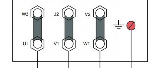
“full star” CT connection diagram (Fig. 2.7) is usually used in networks with a grounded neutral with U³110 kV. In networks with an isolated neutral U £ 35 kV, such a scheme is rarely used - in critical electrical installations (for example, busbar protection). The coefficient of such a circuit is kСХ = 1 (the ratio of the current flowing through the relay to the current flowing through the secondary winding of the CT). In relay KA4, triple the zero-sequence current flows. This is not difficult to prove; according to the method of symmetrical components, the phase currents are equal:
. (2.11)
In relay KA4, the currents of phases A, B and C are added. As a result, the sums over the components of the direct and reverse sequences become equal to zero, since
, (2.12)
and the resulting current flowing through relay KA4 is 3IA0 . Usually in the index the designation of phase A is omitted and written 3I0 .
“partial star”
CT connection scheme is used exclusively in networks with an isolated neutral U £ 35 kV. For such a circuit kСХ = 1 , since the currents in the relay and in the secondary winding of the CT are equal. A feature of the circuit is that from two CTs it is possible to obtain the third phase current - IB , by connecting relay KA3 to the return wire:
I2A + I2C = - I2B , (2.13)
since for a symmetrical three-phase network the equality is satisfied (zero-sequence currents are neglected, because with single-phase ground faults they are disproportionately less than operating ones).
The CT connection diagram in a “triangle” (Fig. 2.9) is usually used in networks with U ³ 110 kV for differential protection of the transformer on the high voltage side. The coefficient of such a circuit can be calculated using Kirchhoff’s first law by finding the currents in the CT node of phase A:
, (2.14)
where we find the current in the relay:
. (2.15)
Considering that, according to the vector diagram (Fig. 2.10), it is easy to calculate:
(2.16)
The diagram (Fig. 2.11) for connecting a CT to a phase difference (previously this scheme was called “incomplete triangle” or “figure of eight” ) is used in networks with an isolated neutral with U £ 35 kV, most often to protect high-voltage electric motors, but sometimes also to protect lines, less often transformers. Similarly, as for the CT connection diagram in “ triangle ” , its. “ triangle ” diagram , so the expression (2.14) is obtained for the node.
Its advantage is the presence of one relay, simplicity. The disadvantage is the low sensitivity during turn short circuits of the motor winding in phase B.
zero sequence current filter circuit is shown in Fig. 2.12. Used in networks with a grounded neutral with U ³ 110 kV for zero-sequence current protection. Since this circuit is a filter, there is no concept of a circuit coefficient for it. 3I0 flows through the relay
-
can be proven similarly to the “full star” scheme.
series connection (Fig. 2.13) is used to increase the load capacity of the CT. For this purpose, CTs with the same kT . Since the current flowing through the CT is the same, and the voltage across the load is divided by two, the load on each CT is halved. Often this circuit is used on the high voltage side of a transformer with a Y/D connection circuit for its differential protection.
A parallel CT connection (Fig. 2.14) is used to reduce kT . If CTs have the same kT , then the resulting transformation ratio will be half as much.
“full star” CT connection diagram (Fig. 2.7) is usually used in networks with a grounded neutral with U³110 kV. In networks with an isolated neutral U £ 35 kV, such a scheme is rarely used - in critical electrical installations (for example, busbar protection). The coefficient of such a circuit is kСХ = 1 (the ratio of the current flowing through the relay to the current flowing through the secondary winding of the CT). In relay KA4, triple the zero-sequence current flows. This is not difficult to prove; according to the method of symmetrical components, the phase currents are equal:
. (2.11)
In relay KA4, the currents of phases A, B and C are added. As a result, the sums over the components of the direct and reverse sequences become equal to zero, since
, (2.12)
and the resulting current flowing through relay KA4 is 3IA0 . Usually in the index the designation of phase A is omitted and written 3I0 .
“partial star” CT connection scheme is used exclusively in networks with an isolated neutral U £ 35 kV. For such a circuit kСХ = 1 , since the currents in the relay and in the secondary winding of the CT are equal. A feature of the circuit is that from two CTs you can get the third phase current - IB , by connecting relay KA3 to the return wire:
I2A+ I2C = - I2B , (2.13)
since for a symmetrical three-phase network the equality is satisfied (zero-sequence currents are neglected, because with single-phase ground faults they are disproportionately less than operating ones).
The CT connection diagram in a “triangle” (Fig. 2.9) is usually used in networks with U ³ 110 kV for differential protection of the transformer on the high voltage side. The coefficient of such a circuit can be calculated using Kirchhoff’s first law by finding the currents in the CT node of phase A:
, (2.14)
where we find the current in the relay:
. (2.15)
Considering that, according to the vector diagram (Fig. 2.10), it is easy to calculate:
(2.16)
The diagram (Fig. 2.11) for connecting a CT to a phase difference (previously this scheme was called “incomplete triangle” or “figure of eight” ) is used in networks with an isolated neutral with U £ 35 kV, most often to protect high-voltage electric motors, but sometimes also to protect lines, less often transformers. Similarly, as for the CT connection diagram in “ triangle ” , its. “ triangle ” diagram , so the expression (2.14) is obtained for the node.
Its advantage is the presence of one relay, simplicity. The disadvantage is the low sensitivity during turn short circuits of the motor winding in phase B.
zero sequence current filter circuit is shown in Fig. 2.12. Used in networks with a grounded neutral with U ³ 110 kV for zero-sequence current protection. Since this circuit is a filter, there is no concept of a circuit coefficient for it. 3I0 flows through the relay
-
can be proven similarly to the “full star” scheme.
series connection (Fig. 2.13) is used to increase the load capacity of the CT. For this purpose, CTs with the same kT . Since the current flowing through the CT is the same, and the voltage across the load is divided by two, the load on each CT is halved. Often this circuit is used on the high voltage side of a transformer with a Y/D connection circuit for its differential protection.
A parallel CT connection (Fig. 2.14) is used to reduce kT . If CTs have the same kT , then the resulting transformation ratio will be half as much.
Scheme of a partial star CT with a relay in the return wire
In a partial star circuit with a relay in the return wire (Fig. 1, c), the sum of the secondary currents of phases A and C or (in case of phase-to-phase short circuits) the current of phase B with the opposite sign passes through the 3KA relay connected to the return wire [L1, p. 42]:
The circuit has the advantage of a partial star circuit (using two CTs) and has the same sensitivity for two-phase short circuits behind the U/D-11 transformer as a full star circuit. Circuit coefficient kcx = 1.
The partial star circuit with or without a relay in the return wire has found widespread use in current protection of lines with voltages up to 35 kV inclusive (i.e. in networks with an isolated neutral).
Relay protection and automation project
Schemes with two current transformers per connection (partial star scheme) are one of the most common in 6-35 kV networks.
Previously, such schemes were used in projects by default at most connections, starting from the line and ending with 35/6 kV transformers. In reality, a partial star circuit usually has the same sensitivity as a full star circuit if you are using a three-relay relay protection system.
However, there is one type of damage in which this relay protection circuit can lead to very unpleasant consequences. We'll talk about this in today's article.
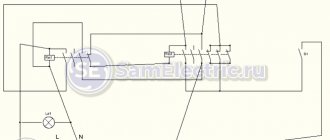
As you probably guessed, this type of damage is a double ground fault. Moreover, only one type of distribution of closure points leads to problems, namely the one shown in Fig. 1
Rice. 1. Option of double ground fault in 6-35 kV networks
The progression of the accident may look like this:
— First, a single-phase ground fault occurs on phase A (or C) in the higher network. OZZ is not an emergency mode and can exist in the network for quite a long time (during the search for “ground”);
— Despite the absence of short-circuit currents, the insulation of healthy phases, including phase B, are under the influence of linear voltages. Due to overvoltage, a breakdown of phase B insulation occurs in the downstream switchgear (for example, busbars or cutting of an outgoing cable);
— We get a double ground fault through phases A (or C) and B, and these points are at different distribution levels. The downstream input protection, made according to a two-transformer circuit, does not detect a double ground fault current, despite the fact that this is already an emergency current;
— Double circuit is disabled by higher-level protection.
I think the situation is clear. In practice, such cases, although relatively rare, do occur.
The first question is that there is a non-selective disconnection of the connection (if the input protection had worked, then the double circuit would again turn into an OZZ, which can be worked with). But that's not the worst thing.
Much worse is that the shutdown occurs with a time delay that should not exist. If the second short circuit was on the buses, then, for example, the LZSh will not work.
It’s even worse if the fault is arc-based – your arc protection simply won’t work (there’s a flash, but no current). The MTZ delay on the linear switch from above can be 1-1.5 seconds, during which the arc will destroy the cell, or even the entire section.
Thus, you should not use two-transformer circuits on the inputs and CBs. On lines and other connections this is not so critical because arc protection is usually not started from their overcurrent protection.
It is also worth analyzing the influence of this factor on checking the thermal resistance of the screens of single-core XLPE cables extending from such substations (with relay protection and protection according to the partial star circuit), in the event of a second short circuit on the cable.
The screens of such cables are checked specifically for a two-phase ground fault, and here it is necessary to correctly determine the shutdown time. Perhaps it will be much higher than the time of your own MTZ. But more about this some other time.