The device presented here is a zener diode for testing the voltage value of an unknown zener diode. A zener diode is an electronic component that maintains a constant voltage across its contacts, and the source voltage Vs must be greater than the zener diode's own voltage Vz , and the current is limited by a resistance Rs , so that its current value was always less than its maximum power.
Diagram of the simplest method for checking zener diode voltage
Radio amateurs and all those who are good friends with electronics know that the task of finding a zener diode with the required characteristics (operating voltage) is boring and painstaking. It happens that you need to go through a lot of different instances until you find the desired Vz value. Checking the status of the zener diode is usually done using a regular multimeter diode scale, this test gives us an accurate idea of the condition of the component, but does not allow us to determine the Vz value. In general, a zener diode tester is a really convenient device when we want to quickly find out the value of the voltage Vz.
Zener diode tester
It only takes a few hours to make this device. It is designed to check the serviceability, determine the pinout and stabilization voltage of zener diodes. But it can also be used to test other semiconductor devices, for example, to determine the breakdown voltage of the emitter junction of a transistor, which are sometimes used as zener diodes. During the test, the task was not to determine the dependence of the stabilization voltage on the flowing current.
The device diagram is shown in Fig. 1. It consists of a step-up voltage converter assembled on a DD1 chip and a VT1 transistor, as well as a specialized module F08508-G. On the Internet, this module (Fig. 2) is positioned as a car battery tester and is a three-digit voltage meter with a digital LED indicator. It allows you to measure DC voltage up to 99.9 V.
A pulse generator is assembled on logic elements DD1.1 - DD1.3, element DD1.4 is a buffer one. The frequency is set by the parameters of elements C2 and R1, and for those indicated in the diagram it is approximately 9 kHz. Pulses from its output through resistor R2 arrive at the base of transistor VT1, which operates in switch mode. When it is open, current flows through the inductor and energy accumulates in its magnetic field.
When the transistor closes, a self-inductive emf appears on the collector and a voltage pulse with an amplitude of about 60 V is formed, which is then rectified by diode VD1, and capacitor C3 is charged to this voltage. Through current-limiting resistor R3, this voltage is supplied to the zener diode under test and to the module input. Using switch SA2, the polarity of the voltage on the zener diode is changed, but not at the input of the module. By taking readings from the module indicator, you can determine the stabilization voltage and pinout of the zener diode. It should be taken into account that if the zener diode is ordinary, it includes one pn junction (VD1 in Fig. 3). Therefore, with a voltage of reverse polarity (plus - to the cathode, minus - to the anode), the breakdown voltage will be indicated; for a zener diode this is the stabilization voltage. When the polarity is changed, there will be a forward voltage at the pn junction; if it is silicon, then this is about 0.6 V. If the zener diode is symmetrical (VD2 Fig. 2), when the polarity is changed, the stabilization voltage changes slightly. But there are also so-called temperature-compensated zener diodes, which include an additional diode (VD3 in Fig. 3). In this case, with one connection polarity, the stabilization voltage will be supplied to the input of module A1, and with the other, the output voltage of the converter will be supplied.
The pulse generator can also be assembled on other microcircuits; fragments of the device circuit in the case of using K561LN2 and K561LA7 (K561LE5) microcircuits are shown in Fig. 4 and fig. 5 respectively.
The device elements are mounted on a breadboard (Fig. 6) using wired wiring. The resistor used is MLT, C2-23, oxide capacitors are imported, capacitor C2 is K10-17. Transistor - any of the KT815 and KT817 series. The power switch and switch are small-sized of any type. The choke is a standard choke from a CFL, which is wound on an W-shaped ferrite magnetic core (Fig. 7).
The usual inductance of such chokes is several millihenries. To connect the devices under study, you can use alligator clips (XS1, XS2). Instead of the module, you can use a digital multimeter in DC voltage measurement mode.
The adjustment comes down to changing the frequency of the generator to obtain an output voltage (without load) of about 60 V. This can be done by selecting capacitor C2 (increasing or decreasing the capacity) or resistor R1 (only in the direction of increasing resistance). The device is powered by a 6F22 battery (Krona), the maximum current consumption is 38 mA.
Author: O. KOLCHURIN, Nizhnyaya Tura, Sverdlovsk region. Source: Radio No. 6/2016
Diagram of a device for testing zener diodes
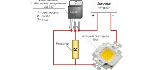
As you can see, the scheme is simple. The voltage from the transformer with two 24V secondary windings is rectified and filtered to obtain a constant voltage of about 80V, then goes to a voltage stabilizer formed by the elements (R1, R2, D1, D2 and Q1), which reduces the voltage to 52V to avoid exceeding the maximum operating voltage limit of the LM317AHV .
Pay attention to the letter index of the microcircuit. For LM317AHV, the input voltage, unlike LM317T , can reach a maximum of 57V.
The LM317AHV contains a DC generator, where a switch (S2) is added along with a resistor (R4) to select two test modes (5 mA and 15 mA) as the current source for the zener diode under test.
This tester is easy to assemble from standard components. A ready-made switching power supply from some DVD or satellite system tuner, and a voltmeter either in the form of an industrial module on a microcontroller, or take a D-830 multimeter.
- REPAIRING A PHONE THAT WILL NOT CHARGE
- CABLE LOOP TESTER
- CIRCUIT REPAIR: DISASSEMBLY-INSTALLATION, SELECTION OF ANALOGUES
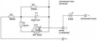
DIY LED and Zener diode tester
In a repair shop, it is often necessary to check the serviceability of various single LEDs and arrays of LEDs and LED matrices. To quickly check such LED assemblies, there are devices for checking the entire matrix or line of LEDs at once, which speeds up repairs; at the output, on its probes, it produces a voltage of more than 200V, at a very low current, which allows you to check even a single LED with a low current at such a high voltage voltage without damaging it.
Unfortunately, such testers are not cheap and they are usually connected to an outlet using a power cord. But you can assemble an LED tester yourself and it’s actually not difficult, and its big advantage compared to a commercial device is that it is completely autonomous and has a built-in battery. In addition to checking LEDs, the device can also test zener diodes; the tester indicator indicates the operating stabilization voltage, and the low current at the output of the device will not damage it during testing. When connecting an LED or a line of LEDs, the indicator will display the rated operating voltage of the LED or the total voltage of the entire line.
Parts needed to create an LED tester:
- Transistor IRF840 or similar powerful ones, for example IRF740;
- Pulse diode FR107 or UF4004;
- Resistor 1 kOhm;
- Resistor 100 kOhm (any one up to 150 kOhm will do);
- Resistor 330 kOhm;
- The capacitor will come from an energy-saving lamp, which usually has a voltage of 400V, the capacity can be from 4.7 to 10 µF;
- A ferrite rod 8x32 mm was taken from the power supply choke from the computer;
- Li-Ion battery 3.7 V;
- Winding wire in varnish insulation with a diameter of 0.8 mm;
- Winding wire in varnish insulation with a diameter of 0.5 mm.
- Mini-voltmeter, you can order one on Aliexpress;
- Battery protection and charging module TP4056, buy one on Aliexpress;
- Phone charging case (or any other suitable size).
DIY LED and Zener diode tester
How to make an LED and Zener diode tester, step-by-step instructions:
Step 1
We insulate the ferrite rod with masking tape, 2 turns of tape is enough. After this, we wind the primary winding with a 0.8 mm wire; I fixed the beginning of the winding with superglue so that it does not unwind. I got 44 turns, that’s how much it fit on the rod, I wound the first winding clockwise.
DIY LED and Zener diode tester
DIY LED and Zener diode tester
Next, we again wrap the masking tape in two layers for interlayer insulation.
DIY LED and Zener diode tester
Now we wind the secondary winding with a 0.5 mm wire in the same direction (clockwise), for this the tip of the winding can be wound with the end of the primary winding, this will be the middle point of the transformer.
DIY LED and Zener diode tester
We managed to wind the first layer of the secondary winding with 54 turns, now we need to lay the interlayer insulation again and continue to wind the next layer with the same wire, then again the insulation layer and again the 3rd layer with the same wire, and this will result in a total of 162 turns in the secondary.
DIY LED and Zener diode tester
At the end, you can insulate the top winding with the same masking tape. The result is a fairly compact transformer.
DIY LED and Zener diode tester
Step 2
We solder the device according to the diagram:
DIY LED and Zener diode tester
For now, just to check, I soldered everything by surface mounting. I soldered probes to the assembled circuit so that I could conveniently check the LEDs. And also soldered the battery.
DIY LED and Zener diode tester
DIY LED and Zener diode tester
After turning on the power, the output (at the probes) without load turned out to be almost 500V. If you need less voltage, you can reduce the number of turns of the secondary winding by unwinding a certain number of turns.
DIY LED and Zener diode tester
Now you can test the operation of the device for checking LEDs and zener diodes on some simple LED, as you can see it lights up and everything works as it should, even though the voltage at the output of the probes is quite large, all because the current is very tiny.
DIY LED and Zener diode tester
Now we can check something more power-hungry, that is, a line of LEDs connected in series, and as we see, everything works fine too.
DIY LED and Zener diode tester
DIY LED and Zener diode tester
Or here’s how the device works with a 220V LED lamp.
DIY LED and Zener diode tester
Here I connected a voltmeter to the output of the device and it shows that the rated voltage of the entire line of LEDs in the lamp is 218V.
DIY LED and Zener diode tester
And the small LED shows a drop of 1.92V.
DIY LED and Zener diode tester
Step 3
When we are convinced that our device for testing LEDs and zener diodes is working, we can begin to upgrade it, add a Chinese small voltmeter, a protection and battery charging board, as well as a power switch and place everything in a suitable case. As a case for the LED tester, I took the case from an old phone charger, it turned out even well, the tester for LEDs, lines of LEDs and zener diodes made by myself is ready!
DIY LED and Zener diode tester
DIY LED and Zener diode tester
DIY LED and Zener diode tester
DIY LED and Zener diode tester
Take home:000
Similar homemade products:
- Tester for LED TV strips and LED strips
- DIY crown (6F22) li-ion
- Simple optocoupler tester
- DIY mini Tesla coil
- Boost voltage converter for power supply…
- Charger for Li-ion batteries for…
- Do-it-yourself eternal Faraday flashlight
- DIY LED light bulb with battery
- IR remote control tester with sound and light indication
Tags:LED, tester, LED tester, zener diode tester
Checking the LED with a multimeter tester for serviceability
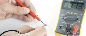
To check for serviceability, no equipment other than a conventional digital multimeter is required. The easiest way is to use probes, which allow you to check elements with any number of leads in any design. After installing the device for ringing, you need to touch the anode with a red probe and the cathode with a black probe. A working diode lights up, and after changing the polarity, the number “1” appears on the screen.
The glow when checking is small, if the lighting is good, it is not visible at all. If the LED element is multi-colored, it is necessary to determine the pinout so that during testing you do not go through the pins at random.
Most multimeters have transistor test jacks that can be used to test diodes. By design, these are 8 holes in the bottom (4 for PNP transistors and 4 for NPN transistors). To test LEDs in PNP, the anode is inserted into socket “E”, the cathode into socket “C”. If the diode is working, it lights up. When tested in NPN, the polarity is reversed.
Important! The disadvantage of this method is that it is impossible to check elements with solder residues without long legs.
To test powerful SMDs you need a driver. The multimeter is connected to it in series, changes in current are visible on the screen. If the element is of low quality, the indicator increases smoothly. The voltage drop is measured by connecting a multimeter in parallel. To determine whether the LED element is suitable for further use, the obtained indicators are compared with the technical documentation data.
If the LED is infrared, if the anode and cathode are correctly positioned, the number 1000 is displayed on the screen; when the polarity is changed, the number 1 is visible.
The main causes of malfunction and failure of LEDs
A feature of LEDs is the reverse voltage, which is only a few volts higher than the drop. The LED fails if even the slightest mistake is made during connection. Super-bright diodes in the backlight burn out during voltage surges. 220 and 12 V lamps are more stable in this regard. Approximately 2% of LED products are delivered with defects; it is advisable to check each one before installation.
LED tester with LCD display
Most modern designs include at least one LED. But before you solder the LED into the circuit, you somehow need to determine that the color and brightness meet your needs. And then calculate the correct resistor value. The proposed microcontroller tester has a current-limiting LED testing principle, as well as a display that shows:
- LED voltage
- Current limit in milliamps (adjustable)
- Desired target voltage (also adjustable)
- Resistor values
LED test circuit
A 9V battery was chosen for power supply for many reasons:
- An alkaline battery has 9.6 to 7 V throughout its life. After subtracting the 1.5V drop on the LM317 regulator, there is still plenty of voltage left for most modern LEDs.
- It's easy to get stable 5V for the microcontroller and LCD.
- The circuit consumes about 40 mA - there is enough capacity.
- The nine-volt battery is compact and has its own plug.
- Alkaline batteries are inexpensive.
- The battery will last for many years with moderate use.
So, this circuit is based on the LM317 DC regulator (see simple version), but with additional components to support the measurements. Calculating the voltage across a 47 ohm resistance determines the current through the LED under test. For example, 0.94 volts into 47 ohms = 20 mA.
The Atmel ATtiny84 microcontroller performs all measurements and calculations, and also updates the information on the display. This microcontroller has 8 KB of memory, although the program takes up less than 4 KB. The program for it is in this archive, see the board files there.
Video of LED tester operation
LEDs
Source: https://elwo.ru/publ/svetodiody/tester_svetodiodov_s_zhk_displeem/5-1-0-900
Do-it-yourself invention of a device for testing TV LEDs using available components
The author was left with a link to a device for checking LED backlighting on a TV. The master will try to repeat the assembly of the device with his own hands, a circuit that he considers quite simple. He studies and explains the diagram, talks about the need for a minimum of details and financial costs for this.
Preparation
First, he disassembles power supplies for antenna amplifiers. Removes transformers, freeing them from control boards. You will need two transformers to make the device. An electronic voltmeter with the ability to measure up to 100 volts is also required.
Prepares a diode bridge, resistor, capacitor, diode and pieces of wire. Gives characteristics for all details.
Connecting components
The author of the video connects the transformers to each other. A diode bridge is connected to them, a diode, a capacitor and other elements are soldered. Finally, connect the voltmeter. All connections are made exclusively by soldering.
In the video, the procedure is commented by the author and the entire connection sequence is shown in detail.
After assembly, an inspection is carried out. The device is connected to the LED strip, and the readings are displayed on the voltmeter.
When the entire system was tested, the author enclosed the contents in a case . Installed the power button, brought out the connectors for the power cord and control wires.
Conducted a check of the LED television system. He commented on the operation of the device, the indicators on the voltmeter, identifying LEDs with incorrect operation that must be replaced.
LED Probe | Homemade catalog
Given the ever-growing interest in light-emitting diodes (LEDs). In particular, today LEDs are installed in all lighting fixtures, replacing outdated incandescent lamps and fluorescent tubes. In new lamps, the type of LEDs installed is most often unknown, so it is recommended to have at least some kind of tester to check their serviceability.
It is not always possible to simply check LEDs with a digital multimeter, since you can see a faint glow when the switch is positioned on the continuity or diode resistance only with low-current LEDs, often red or green. But this test option is not suitable for most white, blue, and some yellow light elements, whose operating voltage reaches 3.3 V.
If you are tired of looking through a magnifying glass at the insides of a light-emitting crystal to presumably determine its anode and cathode, or tired of holding the multimeter probes on the short legs of an unruly little element that constantly tries to slip out, then spend just an hour and assemble your own simple LED probe. The LED probe circuit is so simple that it seems to say why I didn’t think of this before!
- The device assembled according to this scheme has the form of an attachment, which is plugged into the measuring sockets of any multimeter you have at home.
- To assemble the device, all you need is:
- Connecting block pulled from an old Krona battery.
- A suitable Krona battery for powering the probe.
- A micro-button without locking; a clock button from a tablet or phone is also suitable.
- Quick-release socket for transistors - socket with a pitch of 2.54 mm, 3 contacts is enough.
- One 1 kOhm resistor, 0.25 W.
- A plastic plate or part of the housing to secure all the parts.
- Four brass screws.
Drill four holes in a plastic plate of suitable size:
- two for securing the connecting block to which the Krona battery will be connected;
- two for installing homemade plugs from brass screws that will fit into the sockets of an existing multimeter at home.
It is recommended to make the pins without thread along the entire length, not as shown in the photo. The M4 thread is only needed to secure the plugs in the plastic case of a homemade LED set-top box.
- To secure the microbutton and the transistor quick-release socket, you need to cut a separate board from fiberglass.
- From the inside of the board, guided by the electrical circuit diagram, we solder a 1 kOhm, 0.25 W resistor and wires to the transistor socket and microbutton.
- We collect everything into a common housing, connect the output wires to the connecting block for supplying power from the Krona battery and to homemade plugs for measuring voltage with a multimeter.
- For clarity and speed of determining the anode and cathode of the elements being tested, we glue in a free space near the connection socket a schematic image of the LED, according to the connected power wires: red “plus” is the anode, black “minus” is the cathode.
- To carry out measurements: we connect a ready-made attachment with a Krona battery to the multimeter, set the measurement limit from 2 to 20 V DC, plug in any LED being tested at random, press the start testing button, and if the LED is connected correctly and is also working, then it will definitely light up.
- With this probe you can find out:
- LED serviceability;
- pinout of its legs;
- supply voltage.
If you are not very interested in the supply voltage of the LED being tested, then you can do without a multimeter at all.
This very simple device provides enough information about any unknown LED. It is so convenient that it will only delight every electronics engineer.
Vitaly Petrovich, Ukraine, Lisichansk.
Source: https://volt-index.ru/podelki-dlya-avto/probnik-svetodiodov.html
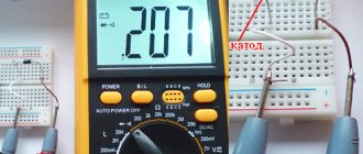
How to use the sampler
The procedure for using the probe is as follows: the probe is inserted with pins into the corresponding sockets of the multimeter, the measurement limit is selected “20” or “200” volts DC depending on the expected stabilization voltage of the zener diode. Next comes the connection to a DC source, the best option is a power supply with adjustable output voltage from zero and current up to 1 ampere. We correctly place the tested zener diode on the contacts, slowly increase the output voltage and look at the multimeter display. There we will see the stabilization voltage of the zener diode we are interested in. But everything will work out, even if there is no regulated power supply, you can use ordinary batteries, connecting them in series until the required voltage is reached.
From user experience : the contacts for installing the zener diode being tested should not be short, but should be able to rotate around their axis, this will make it convenient to test parts with both short and long leads. And if you make paired cuts on the upper edge, then there will be no need to hold the electronic component when checking it. The sample was collected by Babay iz Barnaula.
Forum for discussing the material TEST FOR CHECKING Zener Diodes
In which direction does the current flow - from plus to minus or vice versa? An interesting theory about the essence of electricity. Provides basic information about planar fuses, including their technical characteristics and applications. About the use of wireless power technology for various devices. What are OLED, MiniLED and MicroLED TVs - a brief overview and comparison of technologies.