LED lamps perform their functions fully with high-quality power supply. Even slight fluctuations in current in the circuit provoke visible ripples and impair durability. Similar problems are solved in the process of charging batteries. To correctly solve the above and other problems, a current stabilizer on a transistor is suitable. Self-assembly will help ensure the operating parameters of the device are in strict accordance with the technical specifications. The information presented below will be useful for choosing the optimal electrical circuit.
Connecting a powerful LED to the power supply through a specialized integrated stabilizer
Types of stabilizers
In the simplest version, a current limiter is used from a resistor installed in series with the LED. Standard devices are connected to 5V (12V) sources. By increasing the voltage, accuracy can be improved, but efficiency will decrease.
Transistor voltage stabilizer
The maximum values of the electrical parameters of the source should be 10% greater than the operating values of the LED. The voltage drop is indicated in the accompanying documentation. To calculate the resistor ( R ), use the following formula:
(Up — Uc)/ Ipot,
Where:
- Up – power source voltage;
- Uc – drop on the LED;
- Ipot – current consumption.
Example:
- Up = 5 V;
- Uc = 2.5 V;
- Ipot = 0.25 A;
- R = (5-2.5)/0.3 ≈ 8.33 Ohm;
- the closest value is 8.45 Ohm;
- resistor power = 0.3*0.3*8.45 ≈ 0.75 W.
For your information. The last line of the calculation clearly demonstrates energy losses. A heating resistor will increase the ambient temperature.
Improved circuits are assembled from the following components:
- the transformer changes the amplitude of the signal as needed;
- For rectification, a conventional bridge of diodes is used;
- capacitors smooth out ripples;
- Resistors limit the output currents.
The transistor voltage and current stabilizer is economical. Electrical resistance in the input circuit is installed as a sensor. This component complements the zener diode. Changing the voltage at the emitter allows you to adjust the output parameters automatically without control or intervention from the user.
Instead of a zener diode, the emitter junction of a bipolar transistor can perform similar functions when properly connected to an electrical circuit.
A field-effect transistor is used to connect chains of several LEDs and other powerful loads
Instead of a set of several radio components, it is more convenient to use specialized microcircuits. Such products provide high accuracy in maintaining the operating parameters of the output signal. As in the example with a zener diode, a resistor is installed in a certain circuit to quickly detect changes in current strength.
Separately, it should be noted the pulse circuits of stabilizers. Such products are created on the basis of high-speed electronic keys. The main feature is the ability to operate with relatively high output voltages.
Connection diagram LM317 - voltage stabilizer
As mentioned above, the LM317 can provide any output voltage in the range from 1.2 to 37 V. In order to obtain the required output voltage, we need to connect only two resistors to form a voltage divider.
Depending on the resistance of these resistors, different output voltages can be obtained. Below is a typical connection diagram for LM317 as a voltage stabilizer, taken from the datasheet:
The formula for calculating the output voltage is as follows:
VO = VREF * (1 + R2/R1)
- VO is the output voltage.
- VREF is the reference voltage according to the datasheet (1.25 V).
- R2 and R1 are voltage divider resistors.
Resistor resistance for different voltages:
- 3 volts - R1 (240 Ohms) and R2 (336 Ohms).
- 3.3 volts - R1 (240 Ohms) and R2 (394 Ohms).
- 5 volts - R1 (240 Ohm) and R2 (720 Ohm).
- 9 volts - R1 (240 Ohms) and R2 (1488 Ohms).
- 12 volts - R1 (240 Ohms) and R2 (2064 Ohms).
- 24 volts - R1 (240 Ohms) and R2 (4368 Ohms).
Online calculator LM317 - voltage calculation
To make calculations easier, below is an online calculator for calculating the resistance of the LM317 stabilizer resistors. This calculator provides two calculation options:
- First option : knowing the required output voltage and the resistance of resistor R1, you can calculate the resistance of resistor R2.
- Second option : knowing the resistances of both resistors R1 and R2, you can calculate the output voltage.
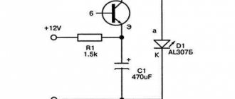
A simple current stabilizer on a transistor
Field-effect transistor current stabilizer circuit
Component parameters and circuit performance characteristics:
- R1 select 1-15 Ohm;
- R2 – from 150 to 250 Ohm;
- D1 – zener diode or resistor of a suitable value;
- Q1 – KT 818 or equivalent;
- power supply voltage – from 8 to 40 V;
- output current – 0.5-4.5A.
Current stabilizer on one transistor
Explanations:
- R2 and D2 form a standard voltage divider;
- by changing the potential on the base, the current in the collector circuit is adjusted;
- when connecting a powerful load, R1 gets very hot;
- to accurately adjust the output parameters, set the variable resistance R2 (change the saturation threshold at the corresponding semiconductor junction);
- if necessary, increase the output current using a composite transistor.
If the calculation is made accurately, in the operating range the current is stabilized with minimal losses. A simple circuit is easy to make with your own hands, even without previous assembly experience.
Characteristics of LM317t
Here are the main parameters of the LM317 stabilizer:
- Input voltage, max: 40 V.
- Output voltage, min: 1.25 V.
- Reference voltage (Vref): 0.1 to 1.3 V.
- Load current, max: 1.5 A.
- Output voltage instability: 0.1%.
- Current Adj: 50…100 mA.
- Housing: TO-220, TO-92, TO-3, D2PAK.
For detailed parameters, see the datasheet in Russian, which can be downloaded at the end of the article.
Assembling a current stabilizer from two transistors
Current stabilizer on LM317 for LEDs
In this circuit, the sensor functions are performed by resistor R2. Its value when connecting LEDs is selected using the formula:
0.6/In (load current).
An increase in In opens VT2, which, in turn, locks the transition of transistor VT1.
Stabilizer with two transistors
Experts consider a significant voltage drop across the main transistor to be a disadvantage of the circuit. There are no problems when connecting several LEDs. However, as the load increases, it is necessary to place VT1 on a large radiator to ensure effective ventilation of the working volume. Such solutions are used to create powerful chargers.
Design and operating principle
The stabilizer ensures constant current when it deviates.
The stabilizer ensures constant operating current of LED diodes when it deviates from the norm. It prevents overheating and burnout of LEDs, maintains constant flow during voltage surges or battery discharge.
The simplest device consists of a transformer, a rectifier bridge connected to resistors and capacitors. The action of the stabilizer is based on the following principles:
- supplying current to the transformer and changing its limiting frequency to the mains frequency - 50 Hz;
- voltage adjustment to increase and decrease with subsequent frequency equalization to 30 Hz.
The conversion process also uses high-voltage rectifiers. They determine the polarity. Stabilization of the electric current is carried out using capacitors. Resistors are used to reduce interference.
Current relays on pulse stabilizer chips
To reduce losses and maintain a wide operating range, ready-made solutions are used. This section presents a switching current stabilizer on the MAX771 chip.
Switching stabilizer
The control voltage is supplied from the divider (R1, R2). If the level set by the manufacturer is exceeded, the output parameters are automatically adjusted.
Modified device models
The maximum load current of this type is perceived up to 4 A. The input voltage by the capacitor can be processed to a level of no more than 15 V. The input current parameter for them usually does not exceed 5 A. In this case, the ripple is allowed to be minimal with an amplitude in the network of no more than 50 mV. The frequency can be maintained at 4 Hz. All this will ultimately have a positive effect on the overall efficiency.
Modern models of stabilizers of the above type cope with a load of around 3 A. Another distinctive feature of this modification is the fast conversion process. This is largely due to the use of powerful transistors that operate with through current. As a result, it becomes possible to stabilize the output signal. A switching type diode is additionally used at the output. It is installed in the system near the voltage node. Heating losses are significantly reduced, and this is a clear advantage of stabilizers of this type.
How to make an LED stabilizer
A simple design of a resistor, capacitor and zener diode can be assembled in just a few minutes. Use a universal mounting plate or a hinged assembly method. The electrical resistance rating is selected taking into account the load parameters. If necessary, install a homemade radiator from a suitable aluminum plate.
Zener diode power supply circuit
Typical connection diagram LM317t
diagram note
- Resistors R1 and R2 are needed to set the output voltage.
- The Cadj capacitor is recommended for ripple suppression. Prevents ripple from increasing as output voltage increases.
- Capacitor C1 is recommended if the LM317 is not located in close proximity to the power supply filter capacitors. A 0.1uF or 1uF ceramic or tantalum capacitor will suffice.
- The Co capacitor improves transient response but does not affect stability.
- It is recommended to use protection diode VD2 if Cadj is used.
- It is recommended to use the protection diode VD1 if Co is used.
Current stabilizers on microcircuits
The use of such an element base slightly increases the cost of the project. However, the use of high-quality microcircuits provides good stabilization characteristics over a wide range of input parameters. Given the good efficiency indicators, you can count on low energy consumption.
TL431
The left side of the figure shows a typical connection diagram for the TL 431 (DA1) microcircuit. The main function is noted - maintaining a voltage of 2.5 V across the control resistor.
Application of the TL 4310 chip
This design is suitable for connecting several dozen LEDs in series with a total power of 12-14 W. Power components are selected taking into account real needs. In the presented example, the voltage drop across the transistor will be 25-35V. Dissipates no more than 1.75 W. In this version, a radiator is not required.
The input resistor (R3) prevents damage to the capacitor when the unit is connected to the network. The load current is limited to a safe level by resistance R3. When choosing LEDs, experts recommend making a power reserve in order to extend their service life while reducing heat generation.
LM7805, LM7812
In the circuit design presented below, the input voltage should be increased. Its level should be 2.5-3V higher than the stabilization rating of this microcircuit.
Connection LM78**
The example shows a DC voltage stabilizer, which is designed for 9-11 W of connected load.
LM317
When connecting a 28-30 W load, this microcircuit provides current stabilization of 100 mA. Input voltage range – from 207 to 240 V.
Stabilizer and lamp connection diagram
The table in the figure shows the values of the adjustment resistor corresponding to certain output parameters.
When choosing a suitable scheme, you should take into account the following:
- minimum and maximum voltages in the power circuit;
- stabilization accuracy;
- device efficiency;
- the difficulty of making a certain design with your own hands;
- cost of components, consumables.
It is recommended to prepare a list of tools, devices, and measuring instruments in advance. Carefully following the instructions discussed above will help you create a functional stabilizer without errors and extra costs.
On the ratio of the dimensions of the inertial stabilizer
When the camera deviates from the horizontal axis, the operator is forced to fix the stabilizer handle in his hand. The moment of force transmitted to the operator's hand is directly proportional to the length of the vertical bar and the weight of the camera, and inversely proportional to the diameter of the handle. Therefore, the ease of camera control depends on the diameter of the handle. To improve tactile sensations about the position of the handle in the hand, it is useful to make small concentric indentations on it.
It must be said that the dimensions of each part of the stabilizer are a compromise between one or another device parameters.
For example, the thinner the handle, the more difficult it is to stabilize the Steadicam when accelerating, but the thicker the handle, the weaker the tactile sensation of the horizon.
Another compromise is the choice between the size and weight characteristics of the structure and the quality of stabilization. The longer the horizontal bar and the heavier the weights at its ends, the higher the quality of stabilization. However, if the length of the horizontal bar increases, its end may fall into the field of view of the lens, and the increase in weight makes carrying the equipment less comfortable. I do not recommend increasing the weight of the equipped stabilizer by more than 2.5 kg, and it is better to adjust the maximum size to your favorite case.