In each electrical circuit there are so-called P - edges (they are also branches, links, sections) and U - nodes. To describe it, there is a system of equations that use two Kirchhoff rules. In them, the edge currents act as independent variables. Therefore, the number of independent variables will be equal to the number of equations, which makes it possible to resolve the given system normally. In practice, methods are used aimed at reducing the number of equations. Among them, the loop current method is very often used, which allows you to perform calculations and obtain accurate results.
The essence of the loop current method
The basic principles of this method are based on the fact that the currents flowing in the edges of the circuit are not all considered independent. The equations for the nodes present in the U-1 system clearly show the dependence of the U-1 currents on them. When an independent current R-U+1 is isolated in the electrical circuit, the entire system can be reduced to the equations R-U+1. Thus, the loop current method is a very simple and convenient selection of independent currents P-U+1 in a circuit.
The use of this calculation method allows for the circulation of a certain virtual circuit current in each independent circuit P-U+1. If any edge belongs to only one specific circuit, then the value of the real current flowing in it will be equal to the circuit current. In the case when an edge is part of several circuits at once, the current flowing in it will be a sum that includes the corresponding circuit currents. In this case, the direction of traversing the contours must be taken into account. Independent circuits cover almost the entire circuit, so the current flowing in any edge can be expressed in terms of circuit currents that make up the complete system of all currents.
Kirchhoff's law - calculation and application
In order to build a system of independent contours, a simple and visual method of creating planar graphs is used. In this diagram, the branches and nodes of the chain are placed on the plane in such a way that mutual intersection of edges is completely eliminated. Using this method, the plane is divided into regions bounded by closed chains of edges. It is they who make up the system of independent circuits. This method is most suitable for manual circuit calculations. However, its application may become difficult or even impossible if the scheme in question does not fit into the framework of a planar graph.
Kirchhoff's first law
Kirchhoff's first law states that in the branches forming a node in an electrical circuit, the algebraic sum of currents is equal to zero (currents entering the node are considered positive, currents leaving the node are considered negative).
Using this law for node A (Figure 1), we can write the following expression:
Figure 1 - Kirchhoff's first law
I1 + I2 − I3 + I4 − I5 − I6 = 0.
Try to apply Kirchhoff's first law yourself to determine the current in a branch. The diagram above shows six branches forming the electrical node B, the currents in the branches enter and exit the node. One of the currents i is unknown.
Write down the expression for node B
I1 + I2 + I3 + I4 + I5 − i = 0 I1 – I2 + I3 − I4 + I5 − i = 0 I1 + I2 + I3 − I4 + I5 − i = 0
Wrong
Construction of a system of equations
Resonance in an electrical circuit
The construction of a system of equations using the method under consideration is carried out according to the following rules:
- For each selected contour, the traversal direction is specified;
- On the left side of the equalities, the sum of all products of the desired currents in the branches and the resistance of the branches is written. The right side records the sum of the voltage sources present in the circuit;
- If the direction of the desired quantity or voltage source is the same as that of the given bypass direction, then the terms are written with a plus sign, otherwise they have a negative value;
- The value of the currents in the branches is replaced by their expression through the circuit currents.
After performing arithmetic operations (opening parentheses, bringing similar terms), a system of equations is obtained in which the unknown quantities are virtual loop currents.
By solving a system of equations, the values of the contour and then the required quantities are obtained.
Basic Concepts
Let's look at an example. In the given diagram, see
Currents in resistors In this case, it is convenient to check the problem using Kirchhoff's first law, according to which the sum of the converging currents at a node is equal to zero. We do everything step by step.
In table The current in resistance R3, which is common to both circuits, is equal to the difference between the circuit currents I11 and I22, since these currents are directed counter to the branches with R3. Controlled elements operate under the influence of control action: thyristors, transistors and others.
Suppose, for example, that the magnitude of the voltage U applied to the current is given and it is necessary to determine the current in the circuit and the distribution of voltages in its sections. Series connection of nonlinear elements. Controlled elements operate under the influence of control action: thyristors, transistors and others.
Examples of solving problems using Kirchhoff's laws
In the diagram of Fig. After the transformations carried out, Fig.
Let's proceed to the main stage - drawing up a system of equations for loop currents. You can read more about complex numbers on our website. Let us determine the parameters of the electrical circuit in Fig. Equations according to the second law are made for independent contours. But using Kirchhoff's law it is convenient to check simple circuits that have one circuit.
System of equations 4. The method of loop currents is that instead of currents in the branches, the so-called loop currents that close in the loops are determined based on Kirchhoff’s second law. Let's write the equations:: 4. In this case, the current in the load becomes equal to zero, and as follows from the relation 1. HOW THE CURRENT FLOWS IN THE CIRCUIT - Read Electrical Diagrams Part 1
Optimized system compilation procedure
According to a simplified method, proceed as follows:
- In the equations on the left side we write the product of the sum of all resistances included in the circuit and the circuit current;
- From the resulting expression, the adjacent loop currents multiplied by the sum of the resistances of the common branch are subtracted;
- On the right is written the sum of the circuit's EMF sources.
Formal approach
The formal approach assumes a matrix form of recording the system of equations. For calculations, the initial data is written in matrix form. The following matrices are used:
- C – in which i rows corresponding to the number of circuits, and j columns corresponding to the number of branches;
- Z – diagonal resistance matrix, the number of rows and columns of which corresponds to the number of branches;
- Ct – transposed matrix C;
- I – matrix of contour values;
- J – matrix of current sources;
- E – EMF matrix.
When compiling a matrix C, each element C ij :
- 0 if branch j is not included in the contour;
- -1, if the branch enters the circuit, the direction of the current is opposite to the circuit;
- 1 – the same, but the direction of the current coincides with the contour one.
In the Z matrix, the diagonal elements are equal to the resistance of the sections, the rest are equal to zero.
The final formula for calculations is:
C∙Z∙Ct∙I=C(Z∙J+E).
This form of writing a solution in matrix form shows how actions are performed on the compiled matrices.
Example of a system of equations
Below is an example of calculating a specific circuit without taking into account the nominal values of the elements.
Example solution
In a given circuit there are three circuits. How to express currents in branches through contour ones:
- i1=I1;
- i2=I2;
- i3=I3;
- i4=I2+I3;
- i5=I1+I2;
- i6=I1-I3.
How to create a system of equations:
- i1R1+i5R5+i6R6=E1;
- i2R2+i4R4+i5R5=E2;
- i3R3+i4R4-i6R6=0
How to substitute contour values :
- I1R1+( I1+I2)R5+( I1-I3)R6=E1;
- I2R2+( I2+I3)R4+( I1+I2)R5=E2;
- I3R3+( I2+I3)R4-( I1-I3)R6=0
After the transformation, the necessary system of equations is obtained:
- (R1+R5+R6)I1+R5I2+R6I3=E1;
- R5I1+(R2+R4+R5)I2+R4I3=E2;
- -R6I1+R4I2+(R3+R4+R6)I3=0.
A system of three equations can be easily solved after substituting known parameters. From the obtained values of the loop currents, the required values can then be found.
This example of solving problems using the loop current method shows that any sufficiently complex circuit can be significantly simplified for solution, guided by the instructions.
Important! The method is not applicable if it is not possible to transform the chain without mutual intersection of branches.
In some cases, the circuit can be simplified by converting the star-connected branches into a triangle.
Exactly the same results are obtained when using the nodal potential method. The calculations are based on searching for the potential of each node (the so-called nodal potential). There are programs that allow online calculation of parameters using the methods discussed.
Alternating current.
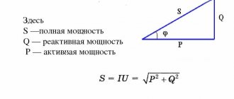
The circuit must maintain a power balance, that is, the energy given by the sources must be equal to the energy received by the receivers.
The last step is to find the real currents; to do this, you need to write down expressions for them. The operation of an active two-terminal network under load in nominal mode is determined by equation 1.
Let us determine the parameters of the electrical circuit in Fig. Uncontrolled nonlinear elements have one current-voltage characteristic; controlled - a family of characteristics.
Determine the current I1 in a given circuit with a current source using the equivalent generator method. To solve such a system, you can use the MathCad program. The circuit must maintain a power balance, that is, the energy given by the sources must be equal to the energy received by the receivers. You can collapse a circuit using equivalent transformations of serial, parallel, and mixed connections.
Read more: Standards for laying cables underground
AGZ EMERCOM RGR No. 1 Calculation of linear DC circuits
Equations according to the second law are made for independent contours. Let us determine the parameters of the electrical circuit in Fig. The loop current is equal to the actual current that belongs only to this loop. You can collapse a circuit using equivalent transformations of serial, parallel, and mixed connections.
The direction of the circuit bypass coincides with the direction of the circuit currents. Operating mode of the electrical circuit Fig. An alternating sinusoidal current or voltage is given by the equation: Here Im is the amplitude of the current. For example, using Kirchhoff's law, which states that the sum of the emf in the circuit is equal to the sum of the voltages in it. The method of loop currents is that instead of currents in the branches, the so-called loop currents that close in the loops are determined, based on Kirchhoff’s second law.
Determine the currents in all branches of the circuit based on the superposition method.
This current-voltage characteristic is plotted using two points 1 and 2 in Fig. To do this, you need to find the voltage in the circuit, which will be common to both resistors, since the connection is parallel. Therefore, the current source circuit Fig. Let's calculate the similarity coefficient.
Draw up a power balance in the original circuit with a current source, calculating the total power of the sources and the total power of the resistance loads. It is recommended to replace circuit nodes a, b, c, d with 1, 2, 3, 4, respectively. The exception is circuits containing more complex star and delta connections. In our case, these currents are directed clockwise. Kirchhoff's Laws - Theory and Problem
Basic principles
Any electrical circuit consists of sections (branches) that form nodes and circuits. To determine the current values through any element, two Kirchhoff laws are used. Direct composition of equations gives a system with their maximum number equal to the number of branches. As a result, if the set of nodes in the chain is Y, and the number of branches is P, then the equations are distributed as follows:
- For U-1 nodes, according to Kirchhoff’s law for currents;
- For branches R-U+1 according to Kirchhoff’s law for stresses.
This quantity is excessive and leads to the formation of a cumbersome system of high-dimensional equations.
To simplify calculations, techniques have been developed that allow reducing the number of equations to acceptable values without reducing the accuracy of the results. The simplest is the loop current method.