Content
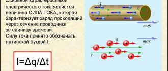
Current strength $I$ is an important characteristic in electricity. It directly depends on the magnitude of the electric charge $q$ transferred by the particles and on the time $t$ during which this charge passes through the cross section of the conductor.
It is not always possible to look inside a conductor, measure the transferred charge and calculate the current strength using the formula $I = \frac{q}{t}$. But it is possible to measure the current using a special device.
This device is called an ammeter . In this lesson you will learn how to use it to measure current and how to properly connect it to an electrical circuit.
The best inexpensive models
The presented multimeters will be useful for repairs, amateur design, and setting up equipment in a home laboratory . These are the best entry-level models.
TOP 4 inexpensive digital multimeters for home.
RESANTA DT 838
The practical and easy-to-use model RESANTA DT 838 is an inexpensive, universal digital multitester designed for home use.
The presented measuring equipment will provide accurate measurement of direct and alternating voltage, current, resistance, temperature, transistor gain, continuity testing of connections, and diode testing.
The multimeter has an insignificant base error of 0.5%.
The delivery set includes a Krona battery, measuring probes, and a proprietary temperature sensor.
Product safety corresponds to IP21 class. The maximum operating voltage is 1000 V.
Specifications:
- speed - 3 measurements per second;
- basic accuracy class - 0.5%;
- constant voltage (U-) - 0.2-1000 V (0.5%);
- alternating voltage (U~) - 200-750 V (1.2%);
- direct current (A-) - 0.002-10 A (1%);
- resistance (R) - 200 Ohm-2 MOhm (0.8%);
- temperature - -20°...1370°;
- power supply - element 6F22 (9 volts);
- overall dimensions - 70×126×28 mm;
- device weight - 137 g;
- Features: continuity testing, diode/transistor testing, manual switching of measurements, sound signal.
Advantages
- compactness;
- temperature measurement;
- wide range;
- democratic price tag.
Flaws
- there is an error;
- long call;
- The probes are not of the best quality.
ROBITON DMM-200
The inexpensive digital multimeter ROBITON DMM-200 will provide accurate measurement of key parameters of electrical circuits with results displayed on a convenient and bright display.
The model is a voltmeter, ammeter and ohmmeter rolled into one.
The device can determine the health of diodes and transistors.
Using the device, it is convenient to check the gain of semiconductor devices and the integrity of the electrical circuit.
The multimeter is equipped with a system for manually selecting the measurement range; for these purposes, there is a convenient rotary switch on the front panel.
Power is supplied from the Krona battery included in the delivery package.
Specifications:
- speed - 2 measurements per second;
- basic accuracy class - 2%;
- constant voltage (U-) - 0.2-1000 V (1%);
- alternating voltage (U~) - 200-750 V (2%);
- direct current (A-) - 0.02-10 A (2%);
- resistance (R) - 200 Ohm-2 MOhm (1%);
- power supply - element 6F22 (9 volts);
- overall dimensions - 70×126×26 mm;
- device weight - 111 g;
- features - continuity test, diode/transistor check, manual switching of measurements, sound signal, overload indicator.
Advantages
- affordable price;
- functionality;
- ease of use;
- detailed user instructions.
Flaws
- delayed continuity signal;
- error in voltage measurements;
- lack of backlight.
PHASE M830B
The lightweight and compact digital multimeter FAZA M830B is an entry-level measuring device that allows you to measure DC and AC voltage, current and resistance.
The device also supports diode and transistor tests. A 9 volt battery (“Krona”) is used as a power source.
The device stands out for its affordable price and the availability of the necessary options.
The basic error of the equipment does not exceed 1%. The product is equipped with measuring probes, a case, and detailed technical documentation.
Specifications:
- speed - 3 measurements per second;
- basic accuracy class - 1%;
- constant voltage (U-) - 0.2-1000 V (1%);
- alternating voltage (U~) - 200-750 V (1%);
- direct current (A-) - 0-10 A (2%);
- resistance (R) - 200 Ohm-2 MOhm (5%);
- power supply - element 6F22 (9 volts);
- overall dimensions - 126x70x26 mm;
- device weight - 88 g;
- features - circuit continuity testing, diode/transistor testing, manual switching of measurements, memory, backlight, auto shutdown.
Advantages
- affordable price tag;
- required set of functions on board;
- ease of use;
- high-quality assembly.
Flaws
- lack of temperature measurement;
- dim lighting;
- small error.
RESANTA DT 830B
The multifunctional compact model RESANTA DT 830B with a 3.5-digit LCD display is a necessary device in the arsenal of any radio amateur and electrician.
The device is an ammeter, voltmeter and ohmmeter in one housing.
Additionally, the device is equipped with the ability to test diodes and transistors.
The multimeter is provided with protection and overload indication, has high sensitivity (100 µV) and a small error (1%).
The delivery set includes technical documentation and measuring probes.
Specifications:
- speed - 3 measurements per second;
- basic accuracy class - 1%;
- constant voltage (U-) - 0.2-1000 V (0.5%);
- alternating voltage (U~) - 200-750 V (1.2%);
- direct current (A-) - 0.0002-10 A (2%);
- resistance (R) - 200 Ohm-2 MOhm (5%);
- power supply - element 6F22 (9 volts);
- overall dimensions - 70×126×28 mm;
- device weight - 137 g;
- Features: diode/transistor testing, manual switching of measurements, overload indicator.
Advantages
- affordable price;
- build quality;
- acceptable accuracy;
- reliability of the design.
Flaws
- the wire is not fixed in the probe;
- lack of sound continuity;
- thin probe wires.
Ammeter
An ammeter is a device for measuring current in an electrical circuit.
In terms of operation and appearance, an ammeter is very similar to a galvanometer. Its design has been modified so that it is possible not only to detect the presence of current in the circuit, but also to measure its strength .
In what units is the ammeter scale calibrated? Since it measures current, its scale will be graduated in amperes .
Different types of ammeters may differ from each other depending on the application. Figure 1, a shows a demonstration ammeter . Such devices are most often used in schools when demonstrating experiments.
Figure 1, b shows an ammeter, which is often used for laboratory work.
Figure 1. Demonstration and laboratory ammeters
As you can see, these two ammeters are designed to measure a specific range of current values. The scale of the first ammeter will show a maximum value of $3 \space A$, and the second - $2 \space A$. It is not recommended to exceed these values, as the devices may fail.
Rules for connecting an ammeter to an electrical circuit
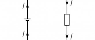
- The ammeter must be connected in series with the device/conductor in which the current is to be measured (Figure 3)
Figure 3. Series connection of an ammeter to an electrical circuit
- The ammeter has two terminals for connecting conductors. The terminal with the “+” sign must be connected to the wire coming from the positive pole of the current source. And, accordingly, the terminal with the “-” sign must be connected to the wire coming from the negative pole of the current source (Figure 4).
Figure 4. Correct connection of the ammeter, taking into account the positive and negative poles of the current source
- You cannot connect an ammeter to a circuit in which there is no current consumer (receiver) (Figure 5). This may cause the device to malfunction.
Figure 5. Impossibility of connecting an ammeter to a circuit without an electricity consumer
Measuring current with an ammeter
The first rule for connecting an ammeter to a circuit is that it is connected in series. Is there a difference where exactly with this connection we place the ammeter?
Let's assemble an electrical circuit. It will consist of a current source, a key, a light bulb and an ammeter (Figure 6).
Figure 6. Series connection of an ammeter (option No. 1)
After closing the circuit, we record the current strength shown by the ammeter.
Now let's move the ammeter in the circuit so that it stands after the lamp, and not before it (Figure 7).
The ammeter will show us the same current value as in the previous case.
Figure 7. Series connection of an ammeter (option No. 2)
Now let’s connect two ammeters to the circuit at once (Figure 8). And what will we see? They will show the same current values , exactly the same as in previous experiments.
Figure 8. Series connection of two ammeters in an electrical circuit
What does this tell us?
In a circuit with a series connection of conductors (so that the end of one conductor is connected to the beginning of another), the current strength in all parts of the circuit is the same.
Why is it the same? The fact is that the charge that passes through any cross section of the conductors of the circuit in $t = 1 \space s$ is the same. After all, the current flows evenly through all the wires of the circuit, without accumulating anywhere. Its flow can be compared to the flow of water through pipes.
Safe and dangerous current limits
Working with electrical circuits can be dangerous if safety instructions are not followed. If we are talking about direct current (the magnitude of the current and its direction do not change over time), then the effects of such current on the human body are shown in Table 1.
| $I$, $ma$ | Impact on the human body |
| 0 — 3 | Not felt |
| 4 — 7 | Itching. Warming sensation |
| 8 — 10 | Increased heating |
| 11 — 25 | Even more intense heating, slight contractions of the arm muscles |
| 26 — 80 | Strong feeling of heating. Contractions of the arm muscles. Convulsions, difficulty breathing. |
| 81 — 100 | Respiratory paralysis |
Table 1. Effect of direct current on the human body
How to avoid getting injured when taking measurements?
To be on the safe side, if in doubt, it is better to read the instructions for the electrical appliance and check that the connection is correct. When taking measurements, it is important to remember about protective measures when working with electric current. Injury can occur even when working with low-current devices. Especially in conditions with high humidity. It is necessary to work in rubberized overalls.
You may be interested in this Features of the SIP piercing clamp
To study ST, scientists came up with measuring electrical devices. Due to the low internal resistance, these meters do not affect the parameters of the electric current in the measured current circuit. The devices are actively used at industrial sites and at home.
Exercises
Exercise No. 1
When the ammeter was connected to the circuit as shown in Figure 9, a, the current strength was $0.5 \space A$.
What will be the readings of the ammeter when it is connected to the same circuit as shown in Figure 9, b? Figure 9. Options for connecting an ammeter to an electrical circuit
The current strength will be exactly the same. The ammeter will show a value of $0.5 \space A$. This is explained by the fact that in this electrical circuit all elements are connected in series. In this case, the current strength in all sections of the circuit is the same.
Exercise No. 2
How can you check the accuracy of an ammeter reading by using another ammeter that has been verified to be accurate?
It is possible to assemble a circuit as in Figure 6 using an accurate ammeter. Record the current value that it will show. Then replace it with another one, the one whose accuracy we want to check. Next, all that remains is to simply compare the readings of this ammeter with those obtained earlier.
You can do this in another way. To do this, you need to assemble a circuit, as in Figure 8, with serial connections of all elements. We already know that in such a circuit two working ammeters should show the same values . The main thing during such a check is to note for yourself which ammeter shows accurate measurement results, so as not to get confused.
Exercise #3
Consider the ammeters given in Figure 1. Determine the scale division value of each ammeter.
What is the highest current they can measure? Redraw the ammeter scale (see Figure 1, a) in your notebook and show what the position of the arrow will be at a current strength of $0.3 \space A$ and $1.5 \space A$. The scale of the demonstration ammeter from Figure 1, a, will have a division value equal to $0.2 \space A$.
The scale of the laboratory ammeter from Figure 1, b will have a division value equal to $0.05 \space A$.
In Figure 10, a we depicted the scale of a demonstration ammeter, which shows the value $I = 0.3 \space A$, and in Figure 10, b - $I = 1.5 \space A$.
Figure 10. Current values on the ammeter scale
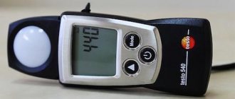
Digital multimeter
The most convenient is a multimeter, in which it is enough to simply set a specific measuring mode. There is no need to additionally specify the tolerance range, since the device itself adapts to the circuit parameters, takes measurements and produces the required result.
The image below shows the first position of the handle, which has several positions demonstrating AC and DC voltage. The first is indicated by V AC (~ symbol), the last DC (—), in the range of volts and millivolts. The current strength A is similar, not being divided into current types, but having a gradation in amperes and milliamps.
In addition, the function of measuring resistance and chain ringing is mandatory.
At the bottom there are several sockets used to activate the measurement wires. The socket marked with the second position COM is used for the main black wire. The third position shows the socket for making basic measurements using the red cord. The permissible limits for voltage and current measurements are shown below. The fourth socket, indicated by position 4 in the image, is used to measure current in amperes, with a maximum limit of no more than 10 A. All readings appear on the display with digital graphics, which is indicated by position 5.
A multitester with an indication of the measurement range is more common, primarily because it costs much less.
When using a multimeter, it is necessary to indicate both the operating mode and the alternating and constant currents. In the same sector, a switch is installed in the required measuring range, expressed in mA, µA and A. The example shown shows 4 socket connections. Two of them are for red wires, measuring up to 200 mA and up to 10 A. Voltage, resistance, capacitance and other indicators are measured using a separate socket.