In one of the previous articles we discussed the main aspects related to working with resistors, so today we will continue this topic. Everything that was discussed earlier concerned, first of all, constant resistors , the resistance of which is a fixed value. But this is not the only existing type of resistor, so in this article we will pay attention to elements that have variable resistance, in particular, variable resistors.
Variable resistor.
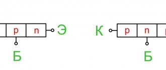
So, what is the difference between a variable resistor and a constant one? Actually, the answer here follows directly from the names of these elements. The resistance value of a variable resistor, unlike a constant one, can be changed. How? This is exactly what we’ll find out; first, let’s look at the conditional circuit of a variable resistor :
It can be immediately noted that here, unlike resistors with a constant resistance, there are three terminals, not two. Now let's figure out why they are needed and how it all works.
So, the main part of a variable resistor is a resistive layer that has a certain resistance. Points 1 and 3 in the figure are the ends of the resistive layer. Another important part of the resistor is the slider, which can change its position (it can take any intermediate position between points 1 and 3, for example, it can end up at point 2, as in the diagram).
Thus, in the end we get the following. The resistance between the left and central terminals of the resistor will be equal to the resistance of section 1-2 of the resistive layer. Similarly, the resistance between the central and right terminals will be numerically equal to the resistance of section 2-3 of the resistive layer. It turns out that by moving the slider we can get any resistance value from zero to R_{max}. And R_{max} is nothing more than the total resistance of the resistive layer.
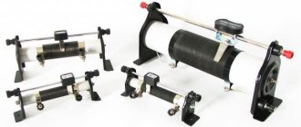
Structurally, variable resistors are rotary , that is, to change the position of the slider you need to turn a special knob (this design is suitable for the resistor shown in the above diagram). Also, the resistive layer can be made in the form of a straight line, so the slider will move along it. Such devices are called slider or slider variable resistors. Rotary resistors can be found very often in audio equipment, where they are used to adjust volume, etc. Their approximate appearance may be like this:
A slider type variable resistor looks a little different:
Often when using rotary resistors, switch resistors are used as volume controls. Surely you have come across such a regulator more than once - for example, on radios. If the resistor is in its extreme position (minimum volume/device is turned off), then when the rotation begins, a noticeable click will be heard, after which the receiver will turn on. And with further rotation the volume will increase. Similarly, when decreasing the volume, when approaching the extreme position there will be a click again, after which the device will turn off. A click in this case indicates that the receiver's power has been turned on/off. Such a resistor looks like this:
As you can see, there are two additional pins here. They are precisely connected to the power circuit in such a way that when the slider rotates, the power circuit opens and closes.
There is another large class of resistors that have a variable resistance that can be changed mechanically - these are trimming resistors. Let's spend a little time on them too.
EP models
A device of this brand, index 1200, is connected via a pair of pins. The potentiometer sensor can withstand four cycles with a cutoff frequency of up to 2300 kHz. The modification is suitable for adjusting the sound and timbre of guitars, and is also used as an element of computer technology.
EP-3000 is characterized by a small spread of resistance. The rheostat-type key is located near the terminals, the housing has special protection. There is a software sampling option, calibration is performed using bridge circuits, and one resistor is provided. This version is not suitable for setting filters and adjusting gain.
Modification EP-2110 is used for digital reverse control. There is a rheostatic switch, a pair of pins in the lower part of the case, and software sampling. The configuration is performed automatically without the participation of bridge circuits.
Types and features
Potentiometers are classified according to the type of resistance change, the type of device housing and various other characteristics and parameters.
Basic division of potentiometers.
By the nature of the change in resistance:
- Linear . Marked with the letter "A". The resistance varies directly depending on the angle of rotation of the movable contact.
- Logarithmic . Marked with the letter "B". When the slider starts moving, the resistance changes quickly and then slows down.
- Exponential . Marked with the letter "C". When you turn the knob, the resistance changes exponentially, that is, at first slowly, then faster. Letter designations may not always correspond to reality, as this depends on the manufacturer of the device. Therefore, to determine the type of potentiometer, it is necessary to study the technical description of this instance.
By type of potentiometer housing:
- Assembly . Installed by soldering to the circuit board.
- Stationary negotiable . They are located on the body of various devices. In turn, revolving potentiometers are divided into several types: - Single-turn.
The sliding element can rotate one revolution, or more precisely, about 270 degrees. A full rotation is not possible, since the rest of the rotation sector contains contact terminals. Single-turn variable resistors have become the most popular in devices that do not require more than one turn for adjustment. - Multi-turn.
The moving contact has the ability to perform several revolutions to increase the accuracy of parameter control. Such variable resistors are usually equipped with a helical or spiral resistive element and are used in devices that require increased resolution and adjustment accuracy. Multi-turn models are most often used in the form of trimmers on the circuit board. - Double.
They include two variable resistors located on the same axis. This makes it possible to adjust two resistances in parallel. In such models, the most popular is the use of resistances with logarithmic and linear dependence. They are used in stereo controls for sound amplifiers, radios and other devices that require simultaneous adjustment of two separate channels.
- Linear (slider) . Such models of potentiometers are divided into types: - Sliding potentiometer.
A single linear potentiometer is used for audio equipment devices. Such models are made of conductive plastic to improve the quality of the product and are used to adjust one channel. — Linear double.
This model is capable of regulating two separate channels at once. Often used to configure stereo equipment in professional audio devices that require control of two channels. — Slider multi-turn.
Its design includes a spindle that converts rotational motion into linear translational movement of the slider against resistance. It is used in places where increased resolution and accuracy are required. This model is installed to adjust parameters on the circuit board.
Also divided into:
- Thin film.
- Wire.
Selecting a resistor by resistance
When an electrical device breaks down in a car, drivers take it to be repaired. But often the culprit of the breakdown is a resistor, the replacement of which does not require the experience of an electrician.
If you decide to change the heater resistor, select an element with the correct resistance parameter. To do this, you need to know the voltage of the car's power source and divide it by the current. Having received the required resistance by calculation, go to the store.
In retail chains you can often find inexpensive, low-quality parts. Buy electrical components from trusted sellers and reliable manufacturers: the pursuit of cheapness can end in an accident in the electrical wiring.
Principle of operation
The operation of the potentiometer is that a voltage of 5 volts is applied to one of the terminals, while the second edge must be grounded. The middle pin is connected to a special controller that provides the necessary information on the throttle valve. When the valve is completely closed, the voltage does not exceed 0.7 V, and in the open position it reaches 4 V.
A potentiometer sensor is attached to the damper body using a screw fixation. The device interacts with the axis of rotation using a special hole in the indicator socket. To properly configure the device, you need to connect the sensor connectors, activate the ignition, and measure the input voltage. This indicator should not exceed 0.7 volts. If the reading is too high, adjust the indicator mount using screws to normal. If you have any doubts about which potentiometer to choose, it is advisable to contact a specialist or service center.
Basic division of potentiometers:
a) the nature of the change in resistance:
- linear (indicated by the letter A) – the change in resistance is directly proportional to the angle of rotation of the sliding contact;
- logarithmic (denoted by the letter B) - the change in resistance occurs quickly from the beginning, then slows down;
- exponential (denoted by the letter C) - the change in resistance occurs slowly at the beginning, then accelerates. Please note that sometimes the potentiometer type designation (letters A, B, C) may be different depending on the manufacturer of the potentiometer, so you should check this with the technical description of the specific unit.
b) body type:
— mounting (for soldering to the board);
— reversible stationary (placed on the body);
| Type | Description | Application |
| Single-turn | The engine rotates one revolution (approximately 270 degrees or 3/4 of a full revolution) | Most often, such potentiometers are used in devices where one revolution is enough to make adjustments. |
| Multi-turn | The resistor motor can be rotated multiple times (mostly 5, 10 or 20) to improve accuracy. In them, as a rule, the resistive element has a spiral or screw shape. | They are used where high accuracy and resolution are required. Multi-turn potentiometers are often used as trimmers on a printed circuit board. |
| Twin | Combines two separate resistors on one shaft, allowing parallel adjustment of two channels. The most common potentiometers are linear and logarithmic resistance. | It is used, for example, in stereo audio volume controls or other devices where it is necessary to simultaneously adjust two independent channels. |
— slider (linear);
| Type | Description | Application |
| Slider potentiometer | Single slide linear potentiometer is mainly designed for audio devices. High quality resistors are often made from conductive plastic. | For one channel |
| Dual slide potentiometer | The double potentiometer, as well as the double reversible potentiometer, allows you to adjust two independent channels. | Often used to control stereo in professional audio systems and other devices where it is necessary to control two channels simultaneously. |
| Multi-turn slide potentiometer | It has a spindle that converts rotational motion into translational linear movement of the potentiometer slide along the resistive element. | Used where high accuracy and resolution are required. A multi-turn slide potentiometer is used as a trimmer on a printed circuit board, but not as often as a rotary multi-turn potentiometer. |
Potentiometer design
A potentiometer most often has 3 terminals: two terminals are connected to each other by a constant resistance, the third terminal has a movable contact that moves along a surface of constant resistance.
Modifications
To find out more precisely what a potentiometer is, a review of some device models will help. First, let's look at the Skal modification. In this series, models under the index 103, 105, 107 are especially popular.
Brief description of devices:
- Skal 103 is a device designed to adjust resistance in an alternating current circuit. This device features exclusively movable contacts. There is one key, a passive resistor, placed near the terminals. A software sampling function is provided; there is no rheostatic mode. The housing marking is P20, the potentiometer is adjusted by levels.
- Model 105 is an automatic device used in AC systems. A passive type resistor is installed, the key is located near the terminals. The modification is optimally suited for computers because it has a high cutoff frequency and a linear distortion parameter of 56 dB.
- Option 107. This device has a level frequency of 2400 kHz, a resistive switch, and passive resistors located in the lower compartment of the case. Its marking is PP21, the maximum lowering band is 2.3 microns, there is a rheostat mode.
How does a potentiometer affect a motor?
Often, owners of modern cars try to squeeze maximum power out of the car by pressing the accelerator pedal all the way. This solution is not successful, since the aggregation between the power unit and the gas pedal occurs through a special throttle sensor (potentiometer). Mercedes, BMW, Volkswagen and most other foreign cars are equipped with a similar device.
The device is designed to regulate the supply of fuel to the engine in dosed portions. In addition, the device monitors the dynamics of pressure on the accelerator pedal and determines the idle speed. The components of a potentiometer for a car are two resistors, one of which is a stable type, the second is a variable analogue. The total resistance of the elements is 8 kOhm.
What is a heater rheostat in a car?
A car is a complex mechanism with autonomous electrical power and many consumers. The car's electrics must always be in working order, since the functionality of the car, the safety and ease of movement of passengers depend on it.
Heater rheostat in a car
Under the hood of the car there is a miniature power station - a generator. There is also a current storage device – a rechargeable battery. Energy is supplied to peripheral consumers through wires, and each electrical device in the car has a control device - a rheostat (RS). This component affects the resistance and current of the electrical circuit by changing the number of sections of the device.