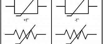
A resistance thermometer is a measuring device that operates over a wide temperature range in various industrial conditions. Additional names for the device are resistance thermal converter and thermistor.
The main advantages of a resistance thermometer are increased stability, closeness of the characteristic to linear dependence and high interchangeability.
Among its disadvantages, one can note the need to use a three-wire or four-wire connection circuit for the accuracy of the measured indicators.
Operating principle of the measuring device
The operation of a thermal converter is based on the property of various materials to change their electrical resistance under different temperature conditions - this parameter is called the temperature coefficient of electrical resistance.
The changed temperature entails a change in the thermal vibration of the metal crystal lattice and a change in the electrical resistance of the sensor. Thus, the higher the temperature of the sensitive sensor, the more significant the vibrations of the crystal lattice, and the higher the level of electrical resistance.
As a secondary temperature sensor, the temperature transducer needs careful calibration before starting the measurement process. This is done by measuring resistance at reference points and then plotting a time dependence on resistance. The thermal converter itself, in this case, must acquire a temperature indicator similar to the measurement environment.
The accuracy of the readings can be affected by the presence of impurities in the sensor metals and possible design defects. Their heterogeneous structure can change the resistance and the speed of reaching stationary indicators for a certain temperature.
To correctly measure temperatures, it is important to ensure proper thermal contact with the measured object.
The dimensions of the sensor should be at the minimum required level, which will eliminate the possibility of increasing the measurement period and will allow recording rapidly changing processes.
What is the difference between a thermoresistance and a thermocouple?
Resistor resistance - formula for calculation
The principle of operation of the vehicle is explained by a change in the conductivity of the control section of the circuit. The thermocouple, despite having a similar name, functions differently. Products in this category are made from two different materials. The connection (working solder) is placed in the measurement area. Temperature fluctuations provoke changes in potentials at the outputs. These readings are recorded with a voltmeter or other suitable device.
Thermocouple operating principle, functional components and measurement methods
For your information. The information provided explains the main practical differences between different types of sensors. The thermocouple is actually an EMF generator, so an additional current source is not needed.
A thermocouple transducer can be used to measure vacuum. To do this, ensure contact of the sensitive area with the filament of the incandescent lamp. The flask is connected by a tube to the working area. A change in gas rarefaction is accompanied by an increase (decrease) in EMF. After calibrating the scale, you can determine the value of the controlled parameter quite accurately.
Thermal converter device
The design of this device consists of a temperature-sensitive element (one or more) and internal connecting wires, which are located in a sealed protective housing, and complemented by external leads for connection to the measuring device.
The sensitive element of the device is a resistor made of metal wire or film, and having leads for connecting connecting wires.
Typical designs of platinum thermal resistances
Manufacturers use various engineering solutions when producing products in this category. To clarify at the comparison stage, you can study the official accompanying documentation or request the necessary data on the company’s website.
Typical vehicle designs
| № | Name | Basic data | Peculiarities |
| 1 | Strain-free | The main element is relieved of loads by aluminum oxide powder filling | Different colors of glaze sealing the end part indicate compliance with a certain temperature range |
| 2 | Hollow nnulus | The working conductor is wound around a hollow cylinder | Construction materials are selected taking into account thermal expansion coefficients |
| 3 | Thin-film | A thin layer of metal is formed on an insulator (ceramic base) | This model is fast and highly sensitive. |
| 4 | Glass-clad wire | This design ensures ideal sealing of the conductor and reliable protection from external influences | Such solutions are used for the manufacture of expensive series of sensors that are designed for difficult operating conditions. |
Typical Platinum Sensor Designs
Metal type thermal converters
These devices are designed to take measurements over a wide temperature range (the specific range depends on the type of metal). Most often, this device is a wire with a cross-section of up to 0.1 mm of a certain length located in an insulated housing. Among these resistance thermometers, the most common devices are those made of platinum, nickel and copper.
Platinum thermal converters are characterized by high stability and accuracy of readings. This device exhibits high resistivity and is capable of taking measurements over a wide range of temperatures. The platinum thermal converter is most widespread in industrial areas around the world.
The nickel meter has the highest temperature coefficient and the largest resistance output. The disadvantage of the device is that when the Curie point (352°C) is exceeded, unpredictable hysteresis of characteristics may occur. Some time ago, it was practiced to install similar thermistors in shipbuilding together with recorders. Now this type of device is common, but still less common than platinum devices.
Copper thermal converters have the most linear characteristic over a limited temperature range. Due to the low resistivity in this type of device, it is necessary to install a wire of increased length. Scope of application of these devices: power plants, electric generators, etc.
Platinum Temperature Meters
Considering the prevalence of metal sensors, it makes sense to provide a brief description of these devices in order to clearly show the comparative characteristics of various types, features, and also describe the scope of application.
In accordance with the standards of GOST 6651 2009 and IEC 60751, for working devices of this type the temperature coefficient value should be 0.00385 ° C-1, for reference devices - 0.03925 ° C-1. Measured temperature range: from -196.0°C to 600.0°C. The undoubted advantages include a high accuracy coefficient, a temperature-resistance characteristic close to linear, and stable parameters. Disadvantage: the presence of precious metals increases the cost of the structure. It should be noted that modern technologies make it possible to minimize the content of this metal, which makes it possible to reduce the cost of products.
The main area of application is temperature control of various technological processes. For example, such a device can be installed in a pipeline in which the density of the working medium strongly depends on temperature. In this case, the readings of the vortex flow meter are corrected with information about the temperature of the working medium.
Thermal converter sensor TSP 5071 produced by Elemer
Carbon thermometers
Most of the characteristics of this device are similar to those of semiconductor thermometers. The manufacture of coal thermometers is based on the principle of sintering tiny coal particles using an industrial method at high pressures. This technology and low cost of materials make carbon thermometers affordable. However, the main drawback of the instruments is low stability, which necessitates their constant calibration or regular stability checks. Also, the disadvantages of the device include the installation of temperature equilibrium in the device itself.
Connection schemes
The working end of the thermocouple is immersed in the medium whose temperature is to be measured. The free ends are connected to the secondary device. If the temperature of the free ends is constant and known, then the connection can be made with copper wire, and if it is not constant and unknown, then it is made with special extension (compensation) wires. The latter uses two wires made of different materials. The wires are selected so that when paired together they have the same thermoelectric properties as the working thermocouple. When connected to a thermocouple, compensation wires extend it and make it possible to divert the cold junction to the measuring device.
Platinum resistance thermometers
Among all types of thermistors, platinum devices are considered the most popular. Firstly, due to the high temperature coefficient of resistance, which makes the operation of these devices extremely simple. Secondly, due to the low oxidation of the metal, which ensures a long service life of the sensors.
In addition, the error in readings with platinum resistors is minimal, which made them the best option for testing other types of sensors. However, in practice, reference thermometers (used for calibration) have to be made of platinum of maximum purity and with a certain temperature coefficient, due to which the cost of reference instruments is tens of times higher than the cost of industrial platinum resistance thermometers. Also, reference thermometers are extremely sensitive to mechanical stress, shaking, vibration and can fail due to thermal shock.
The types of platinum thermistors depend on the type of sensing element used in the device.
Copper sensors (TCM)
TC of copper measuring instruments is 0.00428°C-1, the range of measured temperatures is slightly narrower than that of nickel analogues (from -50.0°C to 150°C). The undoubted advantages of copper meters include their relatively low cost and the temperature-resistance characteristic that is closest to linear. But, the narrow range of measured temperatures and low resistivity parameters significantly limit the scope of application of TCM thermal converters.
Appearance of thermal converter TSM 1088 1
But, nevertheless, it is too early to write off copper sensors; there are many examples of successful implementations, for example, TXA Metran 2700, which is intended for various types of industry, but is also successfully used in housing and communal services.
Considering that platinum thermistors are most in demand, we will consider options for their design.
Types of sensitive elements in platinum thermal converters
Today, the following types of sensitive elements are distinguished:
1. In the form of a “stress-free spiral”.
2. In the form of a “hollow structure”.
3. Film device.
4. Platinum device with glass shell.
The most common and reliable type is the “stress-free spiral”, most often it can be found from Russian manufacturers. Externally, this element may look different - depending on the materials used and the size of the individual parts.
“Hollow design” is a type of device introduced relatively recently. Most often it is in demand at industrial enterprises associated with special production (for example, in the nuclear industry). The type of design of this sensor determines its significant accuracy, reliability and stability in operation. The increased cost of assembly materials makes this part very expensive.
Sensitive elements widely used abroad include the film type, in which a thin platinum layer is applied to a ceramic substrate. This variety has many advantages: low cost, practicality, small dimensions and light weight. The downside of the device is low stability, but recently constant development and research has been carried out to eliminate this drawback.
The device, which is a platinum wire coated with glass, can be called one of the most functional due to its complete sealing and resistance to high humidity. However, this device can only be used at a certain temperature. The cost of this type of element belongs to the above-average segment.
Thermal Resistance: Theory
Recently I was lucky to visit the production of temperature sensors, or rather the Swiss enterprise IST-AG, where they make platinum and nickel thermal resistance devices (RTDs). On this occasion, I am publishing two articles in which the reader will find a fairly detailed description of this type of sensor, a guide to the main stages of the production process, and an overview of the opportunities that arise when using thin-film technologies.
In the first article we deal with the theoretical basis.
Not too exciting, but very useful. (aka thermal resistances or RTDs)
First, it makes sense to understand the terminology. If you are familiar with the question, then feel free to move on to the second part of the article. Or maybe straight to the third.
So, thousands of different products fall under the definition of “temperature sensor”. A sensor can be understood as a ready-made measuring device, where the temperature value in degrees is displayed on the display, and an integrated circuit with a digital output signal, and simply a sensitive element on the basis of which all other solutions are built. Today we are talking only about sensitive elements, which, however, we will also call the word “sensor”.
Resistance thermometers, also known as resistance thermometers and RTDs (Resistance Temperature Detector), are sensitive elements whose operating principle is clear from the name - the electrical resistance of the element increases with increasing ambient temperature and vice versa. You have probably heard of RTDs as platinum temperature sensors such as Pt100, Pt500 and Pt1000 or as 50M, 50P, 100M or 100P sensors.
Sometimes RTDs are confused with thermistors or thermocouples. All of these sensors are used in similar tasks, but even though thermistors are also temperature-resistance converters, thermal resistances, thermistors and thermocouples should not be confused with each other. A thousand articles have already been written about the difference in the structure and purpose of these elements, so I probably won’t repeat myself.
Let me note the main thing: the average resistance thermometer costs several times more than the average thermistor and thermocouple, but only thermoresistance thermometers have a linear output characteristic. The linearity of the characteristics, as well as much higher accuracy and repeatability of measurement results, make thermal resistances popular despite the difference in price.
In short, the characteristics of thermal resistances can be divided into three groups:
- Nominal static response (NSC) and accuracy
- Temperature range at which NSCH is determined and the declared accuracy is ensured
- Sensor housing, lead type and length
In my opinion, only the first point requires explanation.
Nominal static characteristic (NSC)
NSX is a function (in practice, more often a table of values) that determines the resistance-temperature relationship.
The R(T) dependence, of course, is not absolutely linear - in fact, the output characteristic of the thermal resistance is described by a polynomial with known coefficients. In the simplest case, this is a second-degree polynomial R(T) = R0 (1 + A x T + B x T2), where R0 is the nominal resistance of the sensor, that is, the resistance value at 0°C.
The type of polynomial and its coefficients are described in various national and international standards. The current Russian standard is GOST 6651-2009. In Europe, DIN 60751 (aka IEC-751) is more often used, but DIN 43760 is also used at the same time, in North America the ASTM E1137 standard is popular, and so on. Despite the fact that some standards are harmonized, the overall picture is quite sad and there is in fact no single industry standard.
The most popular types of thermal resistances are platinum sensors (Pt 3850, Pt 3750, Pt 3911, etc.), nickel (Ni 6180, Ni 6720, etc.) and copper thermal resistances, for example Cu 4280. Each type of sensor has its own polynomial R(T ).
The names given contain the name of the metal that is used in the manufacture of the sensor, and a coefficient that describes the ratio of the resistance of the sensor at 0 to the resistance at 100°C. This coefficient, together with the value of R0, determines the slope of the function R(T).
In different standards and, as a consequence, in specifications for specific sensors, this coefficient can be expressed differently. For example, a platinum sensor may have an alpha coefficient of 0.00385 °C-1, or a temperature coefficient of 0.385%/°C, or a TCR of 3850 ppm/K, but all three imply the same R(T) relationship.
The metal used uniquely determines the degree of the polynomial R(T), and the coefficients of the polynomial are determined by the temperature coefficient of the metal.
For example, for all platinum sensors the function R(T) has the following form:
R(T) = R0 (1 + A x T + B x T2)
for T > 0
R(T) = R0 (1 + A x T + B x T2 + C x (T-100) x T3)
for T < 0 where the coefficients are selected depending on the type of platinum:
- Pt 3850 ppm/K (the most common characteristic of modern RTDs) A = 3.9083 x 10⁻³ °C-1 B = -5.775 x 10⁻⁷ °C-2 C = -4.183 x 10⁻¹²°C-4
- Pt 3911 ppm/K (the characteristic remains in demand in the Russian Federation, since in the past it was the only one included in GOST) A = 3.9692 x 10⁻³ °C-1 B = -5.829 x 10⁻⁷ °C-2 C = -4.3303 x 10⁻¹²°C-4
The automotive standard Pt 3770 ppm/K, the American Pt 3750 ppm/K or the Japanese Pt 3916 ppm/K will correspond to other sets of coefficients.
The same logic applies to copper and nickel. For example, the NSC of all nickel sensors is described by a sixth-degree polynomial:
R(T) = R0 (1 + A x T + B x T2 + C x T3 + D x T4 + E x T5 + F x T6)
where the coefficients are determined by the temperature coefficient of nickel (Ni 6180 ppm/K, Ni 6720 ppm/K, etc.).
It remains to say about the last parameter of the NSX resistance thermometers - the nominal resistance R0. Most often, sensors with standard R0 are used - 50, 100, 500 or 1000 Ohms, but sometimes resistance resistors with R0 = 2000 and even 10,000 Ohms are required, as well as sensors with “not a multiple” of the nominal resistance.
That is, each type of thermal resistance can correspond to several NSCs with different nominal resistances R0. For the most common characteristics in the Russian Federation, standard designations are used: Pt100 and Pt1000 correspond to platinum with a temperature coefficient of 3850 ppm/K and R0 = 100 and 1000 Ohms, respectively. The designations 50P and 100P, inherited from Soviet reference books, are platinum sensors with a coefficient of 3911 ppm/K and R0 = 50 and 100 Ohms, and the sensors known as 50M and 100M are copper 4280 ppm/K with a nominal resistance of 50 and 100 Ohms.
Sensor accuracy
Thermal resistance accuracy is how much the R(T) dependence of a real sensor can deviate from the ideal HCX. To denote the accuracy of thermal resistances, the concept of tolerance class is used (from the same accuracy class).
The tolerance class determines the maximum permissible deviation from the nominal characteristic, and this deviation is set as a function of temperature - at zero degrees the smallest permissible deviation is fixed, and as the temperature decreases or increases, the range of permissible values increases linearly.
When it comes to tolerance classes, the mess in the current standards only gets worse - even the names of the classes may differ in different sources.
| Other names | Tolerance, °С | |
| Class AA | Class Y 1/3 DIN 1/3 BF 0.1 (if we are talking about a thin film sensor) W 0.1 (if we are talking about a winding sensor) | ±(0.1 + 0.0017 |T|) |
| Class A | 1/2 DIN 1/2 BF 0.15 (if we are talking about a thin film sensor) W 0.15 (if we are talking about a winding sensor) | ±(0.15 + 0.002 |T|) |
| Class B | DIN F 0.3 (if we are talking about a thin film sensor) W 0.3 (if we are talking about a winding sensor) | ±(0.3 + 0.005 |T|) |
| Class C | Class 2B Class BB F 0.6 (if we are talking about a thin film sensor) W 0.6 (if we are talking about a winding sensor) | ±(0.6 + 0.01 |T|) |
| — | Class K 1/10 DIN | ±(0.03 + 0.0005 |T|) |
| — | Class K 1/5 DIN | ±(0.06 + 0.001 |T|) |
The tolerances given in the table comply with most current standards for platinum 3850 ppm/K sensors
, including GOST and European DIN 60751 (IEC-751), which can be called generally accepted with a stretch.
However, there are exceptions here too
. For example, in the American standard ASTM E1137, the tolerance classes of platinum sensors are called Grade and are defined differently:
| Grade A | ±(0.25 + 0.0042 |T|) |
| Grade B | ±(0.13 + 0.0017 |T|) |
If we talk about platinum with other temperature coefficients or about nickel and copper sensors, then we can find other definitions of tolerances.
The tolerance class describes not only the maximum tolerance, but also the temperature range over which this tolerance is guaranteed. You probably already guessed that these ranges can differ significantly in different standards. This is true, and the temperature range depends not only on the tolerance class and type of sensor, but also on the technology by which the sensor is made - with winding sensors the range is always wider.
Read below about what winding and thin-film sensors are.
The picture shows tolerance boxes for platinum sensors with a temperature coefficient of 3850 according to DIN 60751 (IEC-751).
Definitions of tolerance classes for thin film and wound platinum sensors Pt 3850 ppm/K
| Thin film sensor Pt 3850 ppm/K | Winding sensor Pt 3850 ppm/K | ||||
| Tolerance class | Temperature range | Tolerance class | Temperature range | ||
| DIN 60751 (IEC-751) / GOST | DIN 60751 (IEC-751) | GOST | |||
| Class AA (F 0.1) | 0… +150°С | Class AA (W 0.1) | -100… +350°С | -50… +250°С | |
| Class A (F 0.15) | -30… +300°С | Class A (W 0.15) | -100… +450°С | ||
| Class B (F 0.3) | -50… +500°С | Class B (W 0.3) | -196… +600°С | -196… +660°С | |
| Class C (F 0.6) | -50… +600°С | Class C (W 0.6) | -196… +600°С | -196… +660°С | |
By the way, if the documentation for a thermal resistance indicates a range of measured temperatures that is wider than the range provided for by the specified tolerance class, then the declared tolerance class will not be valid over the entire operating range. For example, if a Pt1000 class A sensor is designed to measure temperatures from -200 to +600°C, then it will have an accuracy of ±(0.15+0.002|T|) only at temperatures up to +300°C, and beyond that it will most likely provide class IN.
I provide all these details about the terminology and discrepancies in the standards to convey one simple idea: when choosing a thermal resistance, it is easy to get confused and misinterpret the characteristics of the element. It is important to understand exactly what requirements you place on the element (in absolute numbers, not in classes) and compare them with absolute numbers from the documentation for a specific sensor.
So, thermal resistances are resistors made of platinum or, less commonly, nickel or copper. Two technologies have already been mentioned above - winding (wire) and thin film.
Winding sensors are thermal resistances made of metal wire spirals. There are two main ways to make winding sensors. In the first case, the wire is wound around a glass or ceramic cylinder, after which the structure is covered with an insulating layer of glass. The second method is to place metal spirals in channels inside a ceramic cylinder.
In the manufacture of thin-film sensors, a thin layer of metal is sprayed onto a ceramic substrate, which forms a conductive path, the so-called meander. After this, the sensor is covered with an insulating layer of glass.
Most modern thermal resistances are made using one of these three technologies. Sources contain conflicting opinions about which design is more resistant to vibrations or temperature changes. Cost estimates for sensors of different designs also vary greatly.
In fact, there are no fundamental differences between the characteristics of sensors of different designs; prices for thin-film and winding sensors are also in the same range.
In most cases, it is completely unimportant how exactly the sensor is designed - when choosing a component, only the ratio of price and characteristics of a particular element matters (you just need to remember that tolerance classes for thin-film sensors are defined over a narrower temperature range). However, in some applications thin-film sensors are deliberately preferred over winding sensors. There are three main reasons for this:
- High nominal resistances. Thin film technology allows sensors with R0=1000 ohms to be produced at the same cost as sensors with nominal resistances of 50, 100 or 500 ohms. In addition, sensors are also manufactured with a higher nominal resistance, for example 2000 and 10000 Ohms.
- Small size. A thin-film sensor can be made much smaller than a winding sensor. A standard Pt1000 sensor, for example, can have dimensions of only 1.6 x 1.2 mm.
- The rectangular shape and miniature size of film sensors make it possible to produce not only output thermal resistors, but also SMD components of standard sizes - 1206, 0805, and so on.
Thin-film technology has other interesting properties that make it possible, for example, to reduce the response time of a temperature sensor or to manufacture flow rate sensors based on thermal resistances.
We will talk about this in the next article, which is entirely devoted to the manufacturing process of thin-film sensors. In conclusion, I traditionally thank the reader for their attention and remind you that questions about the use of the products that we write about on Habré can also be sent to the email specified in my profile. update #1:
The article “Thermal Resistances: Manufacturing Process” has been published.
update #2:
All mentioned sensors and modules are available from stock. More information on efo-sensor.ru
Scope of application of resistance thermal converters
These devices are used in the industrial sphere to measure temperature indicators in a variety of working media (liquid, granular, gaseous), in the automotive industry, furnace construction, in heating, refrigeration and climate control electrical engineering - wherever it is necessary to determine the direct dependence of electrical resistance on temperature.
The temperature measurement range of the devices is from -272°C to +1000°C, depending on the type of thermistor. For the accuracy of the data obtained by the sensor, the thermistor design must be stable and sensitive, capable of taking measurements under special conditions (for example, in the presence of an aggressive environment, shaking, vibration, etc.).
Most often, when carrying out measurements with a thermistor, devices such as potentiometers, ratiometers and measuring bridges are additionally used. They help to configure the high accuracy of the thermal converter.
Modern resistance thermal converters are reliable and functional devices that provide measurements at a level inaccessible to other sensors. For optimal measurement results, it is important to select a thermistor type with characteristics suitable for operation in specific conditions and a certain temperature regime.
Sources of uncertainty in on-site temperature measurements
The new standard GOST R 8.625-2006 provides rules for rejecting a resistance thermometer by the consumer. They established that a thermometer can only be rejected if the deviation of the thermometer’s resistance from the NSX lies completely outside the range due to the expanded uncertainty of temperature measurement under operating conditions. Therefore, the problem of assessing the uncertainty that arises when measuring temperature at an object becomes very relevant. Sources of uncertainty in temperature measurement with an industrial resistance thermometer can be divided into sources associated with the physical operating conditions of the vehicle and electrical signal conversion:
– heat-conducting properties of this thermometer design and mounting elements; – transfer of heat by radiation into the environment; – heat capacity of the temperature sensor; – rate of change of measured temperature; – current leakage (grounding quality); – electrical noise; – accuracy of the meter or signal converter.
