Circuit breaker (circuit-breaker) is a contact switching device capable of making, carrying and breaking electric currents under normal circuit conditions, and also capable of making, carrying for a specified time and automatically breaking electric currents under established abnormal electrical circuit conditions, for example during a short circuit (definition based on GOST IEC 60050-441-2015) [1]. This term has a popular jargon among ordinary people: “machine gun”.
A circuit breaker closes and opens electrical circuits using its own contacts. Therefore, it is identified as a contact switching device.
Principle of operation
Kharechko Yu.V. describes in his book [5] the operating principle of a circuit breaker as follows:
“A circuit breaker closes and opens one or more electrical circuits connected to it using its main contacts. Closing is an operation that causes a circuit breaker to be moved from an open position to a closed position; under opening – from the closed position to the open position. »
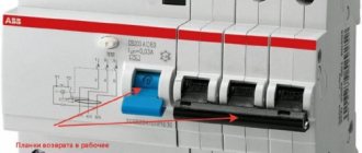
Rice. 1. Example of the appearance of circuit breakers (A - single-pole circuit breaker of the S 200 series, B - three-pole circuit breaker of the S 200 P series)
“The closed position of the circuit breaker ensures the predetermined continuity of its main circuit, the open position – the predetermined gap between the open contacts of the main circuit of the circuit breaker. »
“When switching electrical circuits, the circuit breaker performs switching on and off, as well as switching on followed by automatic switching off. »
“Closing and opening, performed without the flow of electric current in the main circuit of the circuit breaker, refers to its mechanical operation, i.e., to the operation of the circuit breaker in the absence of electric current in its main circuit. »
“Switching on and off, carried out when electric current flows in the main circuit of the circuit breaker, is referred to as electrical operation, i.e., to the operation of the circuit breaker under conditions of electric current flowing in its main circuit. Electrical operation is also called switching. »
“Automatic operation of a circuit breaker occurs when an overload current or short circuit current appears in its main circuit. The overcurrent shutdown time depends on the individual time-current characteristics of the circuit breaker, which must be within the standard time-current zone. »
Setting – instantaneous response indicator
The current value at which the protection is triggered is called the Setting.
This number on the body is a characteristic of the operation of the electromagnetic release. It denotes the maximum value of abnormal current, which during repeated shutdowns will not affect the performance of the device. It is standardized in units of current, and is indicated in numbers or Latin letters. With numbers, everything is extremely simple: this is the face value. But the hidden meaning of the letter designations is worth finding out.
Letters are stamped on machines made according to DIN standards. They indicate the multiple of the maximum current that occurs when the equipment is turned on. A current that is several times greater than the operating characteristics of the circuit, but does not cause a shutdown and does not render the device unusable. Simply, how many times the equipment switching current can exceed the rating of the device and cable without dangerous consequences.
Classification
The IEC 60050‑441 standard and GOST IEC 60050‑441-2015 define several types of circuit breakers [1]:
- " current-limiting circuit-breaker : A circuit breaker with a breaking time short enough to prevent the short-circuit current from reaching its otherwise achievable peak value";
- “ integrally fused circuit-breaker : A combination of a circuit breaker and fuses in one device, in which one fuse is installed in series with each pole of the circuit breaker intended for connection to the phase conductor”;
- " circuit-breaker with lock-out preventing closing : A circuit breaker in which none of the moving contacts can initiate electric current if a command to close is initiated while the conditions that would cause opening";
- “ moulded-case circuit-breaker : A circuit breaker having a supporting body of molded insulating material forming an integral part of the circuit breaker”;
- “ dead tank circuit-breaker : A circuit breaker whose main contacts are located in a grounded metal tank”;
- “ live tank circuit-breaker : A circuit breaker whose main contacts are located in a tank isolated from the ground”;
- “ air circuit-breaker : A circuit breaker whose contacts open and close in air at atmospheric pressure”;
- “ oil circuit-breaker : Automatic switch whose contacts open and close in oil”;
- “ vacuum circuit-breaker : A circuit breaker whose contacts are opened and closed in a high-vacuum enclosure”;
- “ gas-blast circuit-breaker : A circuit breaker in which an electric arc is formed in a gas flow”;
- “ sulphur hexafluoride circuit-breaker, SF6 circuit-breaker : A circuit breaker whose contacts open and close in sulfur hexafluoride (SF6 gas)”;
- " air-blast circuit-breaker : A gas-blast circuit-breaker in which the gas used is air."
Circuit breakers used in building electrical installations are typically molded case air circuit breakers. Some circuit breakers are current-limiting circuit breakers. Sometimes circuit breakers with built-in fuses are used.
The IEC 60898-1 standard and GOST IEC 60898-1-2020 [2] establish the following classification of circuit breakers by terminal type:
circuit breakers with threaded terminals for external copper conductors; circuit breakers with threadless type terminals for external copper conductors; circuit breakers with quick connect spade terminals for external copper conductors; automatic switches with threaded type terminals for external aluminum conductors.
According to the mounting method, the IEC 60898‑1 standard and GOST IEC 60898-1-2020 [2] classify circuit breakers as follows:
circuit breakers, the electrical connection of which is not associated with mechanical fastening; circuit breakers, the electrical connection of which is associated with a mechanical fastening, for example: plug-in type, bolted type and screw-in type circuit breakers.
The IEC 60898‑1 standard and GOST IEC 60898-1-2020 [2] establish the following classification of circuit breakers according to the number of poles:
single-pole circuit breakers; two-pole circuit breakers with one protected pole; two-pole circuit breakers with two protected poles; three-pole circuit breakers with three protected poles; four-pole circuit breakers with three protected poles; four-pole circuit breakers with four protected poles.
The IEC 60898-2 standard and GOST IEC 60898-2-2011 [3] establish a different classification for universal circuit breakers according to the number of poles:
single-pole circuit breakers; two-pole circuit breakers with two protected poles.
Purpose and requirements
Kharechko Yu.V. in his dictionary [5] focuses on the fact that:
“The main purpose of the circuit breaker, as follows from the requirements of the IEC 60364-4-43 standard and GOST R 50571.4.43 developed on its basis, is to protect against overcurrent the conductors of electrical circuits in the electrical installation of a building in order to ensure electrical and fire safety. The circuit breaker must carry for a long time without disconnecting any electric current, the value of which does not exceed its rated current, and promptly disconnect electrical circuits when an overload current or short-circuit current appears in them. »
[5]
“ With system grounding types TN‑C, TN‑S and TN‑C‑S, the circuit breaker can also be used to provide protection against electric shock as part of a protective measure such as automatic power off. The basic requirements for automatic power off in electrical installations of buildings are set out in sections 411 “Protective measure - automatic power off” of the IEC 60364-4-41 standard and GOST R 50571.3 developed on its basis. Chapter 1.7 “Grounding and protective electrical safety measures” of the Electrical Installation Rules, seventh edition, sets out outdated requirements for providing protection against electric shock, rewritten from the previously valid GOST R 50571.3–94. Chapter 1.7 “Grounding and protective electrical safety measures” of the Electrical Installation Rules, seventh edition, sets out outdated requirements for providing protection against electric shock, rewritten from the previously valid GOST R 50571.3–94. »
International requirements for circuit breakers for non-domestic purposes are set out in the IEC 60947-2 standard, which is used in conjunction with the IEC 60947-1 standard. National requirements for them are contained in GOST R 50030.2-2010, which is used in conjunction with GOST IEC 60947-1-2017.
The IEC 60947-1 standard and GOST IEC 60947-1-2017 are intended to harmonize general requirements and recommendations related to low-voltage switching and control equipment, with the aim of unifying them in the relevant device classes and eliminating the need for testing to different standards. Both standards set out requirements and recommendations that are common to low-voltage switching and control equipment intended for operation in AC electrical circuits with voltages up to 1000 V and DC circuits up to 1500 V inclusive. The requirements of these standards are applied in conjunction with the requirements of other standards that are part of the IEC 60947 “Low-voltage switching and control equipment” complexes, GOST IEC 60947 and GOST R 50030.
The IEC 60947‑2 standard and GOST R 50030.2 apply to circuit breakers designed to operate in AC electrical circuits with voltages up to 1000 V and DC circuits up to 1500 V inclusive. Such circuit breakers can have any rated currents, various designs and methods of application. The standards also contain additional requirements for circuit breakers with built-in fuses.
The specified circuit breakers are used in low-voltage distribution devices installed in various buildings, at transformer substations, in distribution points, etc. These circuit breakers are also used in input distribution devices, in input devices, in main distribution boards and other low-voltage distribution devices of residential electrical installations , public, industrial and other buildings.
International requirements for circuit breakers for electrical equipment (ABO), which are specifically designed to protect electrical circuits in electrical equipment, are set out in the IEC 60934 standard. National requirements for these circuit breakers are contained in GOST IEC 60934-2015. These circuit breakers are used in AC electrical equipment circuits with voltages up to 440 V, and DC circuits with voltages up to 250 V inclusive. The rated current of the air cooler cannot be more than 125 A.
International requirements for circuit breakers for domestic use intended for use in electrical installations in buildings are set out in the standards IEC 60898-1 and IEC 60898-2. National requirements for them are contained in GOST IEC 60898-1-2020 and GOST IEC 60898-2-2011.
The GOST IEC 60898-1-2020 standard provides requirements for air circuit breakers whose contacts close and open in air at atmospheric pressure. Automatic switches are designed to operate in alternating current electrical circuits with a frequency of 50 and (or) 60 Hz. They must have a rated voltage of no higher than 440 V, a rated current of up to 125 A and a rated short-circuit switching capacity of no more than 25,000 A.
Circuit breakers for household and similar purposes are intended for use by ordinary persons and do not require maintenance. These circuit breakers may have one or more current ratings. However, the mechanism by which the circuit breaker switches from one rated current value to another must be inaccessible to the consumer under normal operating conditions, and the switching itself must be possible only with the help of a tool.
Circuit breakers, the rated current of which is regulated by means available to the consumer, as well as circuit breakers intended to protect electric motors, are not considered in the IEC 60898‑1 standard and GOST IEC 60898-1-2020.
With the help of circuit breakers, the design of which complies with the requirements of the IEC 60898‑1 standard and GOST IEC 60898-1-2020, the isolation function can be implemented in electrical installations of buildings. That is, household circuit breakers can be used as disconnectors.
The IEC 60898‑2 standard and GOST IEC 60898-2-2011 establish additional requirements for single-pole and double-pole circuit breakers1, also intended for use in DC electrical circuits and having a rated voltage of up to 220 V (single-pole) and up to 440 V (double-pole), rated current up to 125 A and rated short-circuit switching capacity (for direct current) up to 10,000 A inclusive.
Selecting a circuit breaker. Basic Rule
It is necessary to select a circuit breaker based on the cross-sectional area of the wire that this circuit breaker protects (which is connected after this circuit breaker). And the cross-section of the wire is based on the maximum current (power) of the load.
The algorithm for selecting a circuit breaker is as follows:
- We determine the power and current of the line consumers that will be fed through the machine. The current is calculated by the formula I=P/220, where 220 is the rated voltage, I is the current in amperes, P is the power in watts. For example, for a 2.2 kW heater the current will be 10 A.
- We select the wire according to the cross-section selection table depending on the current. A cable with a conductor cross section of 1.5 mm² is suitable for our heater. In the worst conditions in a single-phase network, it holds a current of up to 19A.
- We choose a machine so that it is guaranteed to protect our wire from overload. For our case - 13A. If you install a machine with such a rated thermal current, then at a current of 19A (one and a half times higher), the machine will work in about 5-10 minutes, judging by the time-current characteristics.
Is it a lot or a little? Considering that the cable also has thermal inertia and cannot instantly melt, this is normal. But considering that the load cannot just increase its current by one and a half times, and in these minutes a fire can occur - this is a lot.
Therefore, for a current of 10 A, it is better to use a wire with a cross-section of 2.5 mm² (the current with an open installation is 27 A), and a 13 A machine (if it is exceeded by 2 times, it will work in about a minute). This is for those who want to play it safe.
The main rule will be this:
The wire current must be greater than the current of the machine, and the current of the machine must be greater than the load current
Iload < Iaut < Iprov
This refers to maximum currents.
And if there is such a possibility, the rating of the machine should be shifted towards the load current. For example, the maximum load current is 8 Amperes, the maximum wire current is 27A (2.5mm2). The machine should be chosen not for 13 or 16, but for 10 Amperes.
Here is the machine selection table:
Table for selecting a circuit breaker based on cable cross-section
The choice of circuit breaker clearly depends on the cable cross-section. If the current of the machine is selected more than necessary, then the cable may overheat due to the flow of high current. If the machine is selected correctly, then if the current exceeds it will turn off and the cable will not be damaged.
Table for selecting a machine according to cable cross-section
Pay attention to the cable routing methods (installation type). Depending on where the cable is laid, the current of the selected circuit breaker may differ by 2 times!
According to the table, we have the initial cable cross-section, and select a circuit breaker for it. For us, as electricians, the first three columns of the table are most important.
Table for selecting a circuit breaker based on load power
Table of consumption and current of the circuit breaker according to the power of devices
It can be seen that the manufacturer recommends different time-current characteristics for different electrical appliances. Where the load is purely active (different types of heaters), the characteristics of the machine “B” are recommended. Where there are electric motors - “C”. Well, where powerful engines with difficult starting are used - “D”.
The time-current characteristic D is not included in this table because it is not for domestic use. More details about starting engines are described in the article about connecting an electric motor through a magnetic starter. And also about turning on the solid-state relay.
Design
Let's take a closer look at the design of circuit breakers for household use, which are produced in accordance with the requirements of the standards IEC 60898‑1 and IEC 60898‑2, GOST IEC 60898-1-2020 and GOST IEC 60898-2-2011.
Most of the information you will read below is based on materials from the book by Yu.V. Kharechko [5].
Kharechko Yu.V. describes the circuit breaker design as follows:
“A circuit breaker has a main circuit and may have a control circuit and an auxiliary circuit.
The main circuit combines all the conductive parts of the circuit breaker included in the electrical circuit that it is intended to close and open.
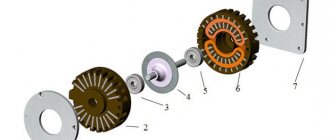
Rice. 2. Design of a single-pole circuit breaker of the S 200 series (the figure is borrowed from the book [4] by Yu.V. Kharechko)
Figure 2 shows:
- 1 – control element;
- 2 – conclusions;
- 3 – main contact;
- 4 – arc extinguishing chamber;
- 5 – thermal overload release (a type of overcurrent release);
- 6 – electromagnetic short circuit release
The control circuit of a circuit breaker is designed to make it close or open, or both. This circuit includes the conductive parts of the circuit breaker used to control it, excluding those parts that form part of the main circuit of the circuit breaker.
The auxiliary circuit combines all the conductive parts of the circuit breaker intended to be included in an electrical circuit used, for example, for remote indication of its switching position. This circuit does not include the conductive parts of the circuit breaker, which are part of its main circuit and control circuit.
To equip a circuit breaker with a control circuit and an auxiliary circuit, one or more additional devices must be attached to it, such as an auxiliary contact, a shunt release and an undervoltage release.
An auxiliary contact is a switch with one or more control contacts and/or auxiliary contacts, which is mechanically actuated by a circuit breaker. For automatic circuit breakers, a position block contact (BCP) is produced, intended to indicate the switching position of the circuit breaker, and a trip block contact (BCS), intended to indicate the operation of the circuit breaker.
When the main contacts of the circuit breaker are closed, the closing contacts of the BCP are closed, and the breaking contacts are opened. When an automatic circuit breaker opens its main contacts due to the appearance of an overcurrent in its main circuit, under the influence of an independent or undervoltage release, as well as when the automatic circuit breaker is manually controlled, the closing contacts of the BKP are opened, and the breaking contacts are closed.
The use of position block contacts in the auxiliary circuits of circuit breakers makes it possible to implement an alarm system and control of their switching position in the electrical installation of a building. In addition, BCPs can be used in control circuits of other switching devices that are used in the same electrical installation of a building.
When the main contacts of the circuit breaker are closed, the closing contacts of the BCS are closed, and the breaking contacts of the BCS are opened. The BCS contacts return to their original position in two cases: when the circuit breaker opens its main contacts due to the appearance of an overcurrent in its main circuit, and when the circuit breaker is turned off using an independent release or an undervoltage release. When manually opening the circuit breaker, the BCS contacts do not change their switching position. Trip auxiliary contacts are typically used in auxiliary circuits to signal tripping by an overcurrent circuit breaker, but they can also be used in control circuits of other switching devices installed in a building's electrical installation.
Shunt release and undervoltage release are used to control the circuit breaker.
The main circuit of a circuit breaker consists of one, two, three or four poles. A pole as that part of a circuit breaker connected exclusively to one electrically independent conductive path of its main circuit, equipped with contacts designed to make and break the main circuit, excluding those parts which provide the means for mounting and operating all the poles together.
The most widely used in electrical installations of buildings are single-pole circuit breakers, intended for use in single-phase two-wire electrical circuits, and three-pole circuit breakers, which are used in three-phase three-wire and four-wire electrical circuits. In single-phase two-wire and three-phase four-wire electrical circuits, two-pole and four-pole circuit breakers are also used, respectively.
To perform the function of overcurrent protection, the circuit breaker is equipped with protected poles. The remaining pole of the circuit breaker, if any, may be the unprotected pole or the switching neutral pole.
The protected pole is equipped with an overcurrent release. The unprotected pole does not have an overcurrent release, but is otherwise capable of the same operation as the protected pole of the same circuit breaker. The switching neutral pole is designed to switch the electrical circuit of the neutral conductor, but is not intended to have short-circuit switching capacity.
In the main circuit of each pole of the circuit breaker there are main contacts. The main contact is a contact included in the main circuit of the circuit breaker and designed to conduct, in the closed position, the electric current flowing in its main circuit.
When the main circuit of the circuit breaker, through which electric current flows (especially overcurrent), is opened, electric arcs may occur between the disconnected parts of the main contacts. Therefore, circuit breakers are equipped with arc contacts on which an electric arc is expected to occur.
The arc contact is usually the main contact. It has a special design of conductive parts, which ensures the movement of the electric arc into the arc-extinguishing chamber , where it is broken into several parts by metal plates and intensively extinguished.
In a multi-pole circuit breaker, the moving contacts of all poles (except for the switching neutral pole) must close and open the main circuit almost simultaneously in both automatic and manual operation. The contacts of the switching neutral pole should open later and close earlier than the contacts of the other poles of the circuit breaker.
The control circuit of the circuit breaker contains control contacts , which are mechanically actuated by the same circuit breaker. Auxiliary contacts , if used, are part of the auxiliary circuit of the circuit breaker and are mechanically actuated by the same circuit breaker.
Each circuit breaker is equipped with one or more releases that are designed to initiate:
automatic opening of the main contacts in the event of an overcurrent in the main circuit of the circuit breaker; automatic opening of the circuit breaker when the voltage decreases or other characteristics of the electrical circuits and electrical equipment connected to it change; remote shutdown of the circuit breaker.
A release is a device mechanically coupled to or incorporated into a circuit breaker that releases a holding device in the circuit breaker mechanism and initiates its automatic opening. To perform overcurrent protection functions, automatic circuit breakers are equipped with overcurrent releases . Circuit breakers can be equipped with independent releases and undervoltage releases.
An independent release is a release excited by a voltage source. It is designed for remote control of a circuit breaker. It is used in cases where there is a need to remotely turn off some electrical circuits using circuit breakers.
After applying voltage to the control circuit of the independent release, its electromagnetic mechanism acts on the holding device of the circuit breaker, initiating the opening of the contacts of its main circuit. The control signal for the independent release can be generated manually, for example, using a push-button switch with a normally open contact. The control signal can also be generated by some switching or electronic device upon the fulfillment of some predefined conditions, for example, by a timer when a set hour has arrived.
The circuit breaker is turned on manually after its remote shutdown using an independent release.
An undervoltage release is a release that initiates the opening of the circuit breaker, with or without a time delay, when the voltage at the release terminals drops below a predetermined value. Its main purpose is to encourage the circuit breaker to turn off electrical equipment when the voltage drops unacceptable for it. An undervoltage release will typically cause a circuit breaker to trip when its control circuit voltage drops to 75% of its rated value (e.g., 230 VAC) or less, and will also prevent the circuit breaker from closing if that circuit voltage is less than 85% of that voltage. rated voltage.
Each circuit breaker has a free trip mechanism , which ensures that the main contacts are opened at the moment the circuit breaker is turned on if an overload current or short circuit current begins to flow in its main circuit.
This mechanism allows the overcurrent circuit breaker to switch off at the moment when it is manually controlled. For example, when manually operating a circuit breaker to turn on an electrical circuit in which there is a short circuit, the short circuit current will begin to flow through the main circuit of the circuit breaker when the main contacts are closed. Under its influence, the overcurrent release will release the holding device in the circuit breaker mechanism. The main contacts of the circuit breaker will automatically open, despite the fact that during the period under consideration manual control to close them is still ongoing.
Each circuit breaker is equipped with an indication of its switching position, which allows you to determine in which position (closed or open) its main contacts are located. For this purpose, the circuit breaker may be equipped with a position indicator . Otherwise, the switching position of the circuit breaker indicates the control , which must have two clearly distinguishable rest states corresponding to the closed and open positions of its main contacts.
When a circuit breaker automatically trips due to the appearance of an overcurrent in its main circuit, the control element of the circuit breaker may occupy a separate, third position. The control of a vertically mounted circuit breaker typically moves up and down. When it moves up, the main contacts of the circuit breaker close, and when the control moves down, they open. The closed position of the circuit breaker is indicated by the sign I (vertical line), the open position - by the sign O (circle).
For electrical connection of the circuit breaker to the conductors of external electrical circuits, terminals are used, which can be threaded type terminals and threadless type terminals . Typically, circuit breakers are equipped with threaded terminals: columnar, screw, pin, plate, and less often - terminals for tips. The most common type of terminal for modern circuit breakers is a column terminal , into a hole or cavity in which a conductor is inserted and clamped with one or more screws. Some companies are starting to produce circuit breakers equipped with threadless terminals. »
Calibrated characteristic of the device rating
This characteristic is the operating parameters of a thermal release or its semiconductor analogue. It is a coefficient by which we multiply to obtain the overload current that the device may or may not hold for a certain period of time. The value of the calibrated characteristic is established during the production process and cannot be adjusted at home. They select it from the standard range.
The calibrated characteristic indicates how long and what kind of overload the machine can withstand without disconnecting the circuit section from the power supply. Usually these are two numbers:
the lowest value indicates that the machine will pass current with parameters exceeding the standard for more than an hour. For example: a 25A circuit breaker will pass a current of 33A for more than an hour without disconnecting the protected section of wiring
the highest value is the limit beyond which shutdown will occur in less than an hour. The device indicated in the example will quickly turn off at a current of 37 amperes or more
If the wiring runs in a groove formed in a wall with impressive insulation, the cable will practically not cool during overload and the accompanying overheating. This means that in an hour the wiring can suffer quite a bit. Maybe no one will immediately notice the result of the excess, but the service life of the wires will be significantly reduced. Therefore, for hidden wiring we will look for a switch with minimal calibration characteristics. For the open version, you don’t have to focus too much on this value.