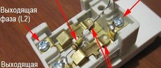
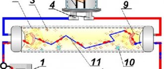
This device is a must-have attribute of any room. When choosing it, you can prefer a regular one or one that has indicators. To make the right decision, you need to form an opinion about the pros and cons of each option. Having figured out what a backlit switch is, you can easily determine whether it is needed and how to choose it correctly.
Illuminated switch design Source sovet-ingenera.com
What are the features of such switches?
When choosing such products, many people pay attention to their practicality, reliability and functionality. Conventional devices have a simpler design and do not require additional effort during installation. However, in most cases, the connection for a switch with an LED does not involve any special difficulties.
Circuit diagram of the switch Source sovet-ingenera.com
Use brings additional convenience, allowing you to easily find the keys in low visibility conditions. The backlit switch has installed indicators. This is especially convenient when you need to turn on the light in a room with insufficient lighting. Having entered it, a person can immediately see where exactly the device is located and use it.
Illuminated switch Source sovet-ingenera.com
Installation and connection of switching devices with backlight
The indication chain has almost no effect on the operation of the switch, and for its operation it does not matter which side the phase wire comes from. Therefore, for standard key devices, the presence of backlight does not change anything. The device is also mounted in a phase wire break. The supply core is also connected to it, and conductors depart according to the number of loads. But there are several points.
Installation of switches with one key
Installation and connection of single-key devices has no special features. But we must take into account that the indicator can be located either at the top of the device’s panel or at the bottom (sometimes in the middle). Therefore, there is no point in relying on the position of the lamp to determine the on position of the keys.
Switches with an upper and lower location of the light-emitting element.
Features of connecting a device with two keys
When connecting a two-button backlit lighting switch, you must keep in mind that in most cases only one pair of contacts is equipped with an indication. Therefore, when one of the keys is turned on, the light-emitting element will go out and the device will remain without an indication. This does not matter if the device switches two lighting systems in one room. But it can be important if the switch controls the light in two different rooms (toilet and bathroom in a separate bathroom).
Illumination circuit of a two-key device.
Connecting a pass-through switch with an indication circuit
For a pass-through device, the described principle of deshunting the circuit is of little use. If the lighting circuit is broken, the contacts of one switch may be closed. And if the backlight is installed on only one pair of contacts (like a two-key switch), then when the light is turned off this circuit will be bypassed.
Diagram of operation of pass-through switches with indication.
To eliminate this drawback, it is necessary to install illuminating elements on each pair of contacts and use two light emitters. This requires additional space inside the device and design refinements in the design of the front panel. Therefore, for marching switches, parallel circuits for connecting radiating elements are used.
Operation of pass-through switches with indication of the on position.
In the first diagram, additional elements are connected in parallel to the fixed contacts. In this case, when the circuit is broken and the lighting is off, both indicators will light up. With the main circuit assembled, both bulbs will be unpowered.
Operation of pass-through switches with indication of load activation.
Another option is a power-on indication. In this case, the indicator lights light up when the lamp is turned on. The disadvantages of such a connection are:
- the need to lay a third wire between the marching switches;
- the need to lay the neutral wire N to the switches.
And the practical usefulness of indicating the on state of the lamps is questionable. These indicators will light even if the lamp is not installed in the lamp or the cable is forgotten.
Let's look at the visual connection of the wires.
Advantages and disadvantages of such devices
The advantages of a backlit switch include the following features:
- The backlight allows you to immediately find it in the dark without having to feel the wall nearby.
- The presence of lighting allows you to keep the wall surface next to the switch clean. In this case, there will be no fingerprints on the wallpaper due to the inaccurate determination of its location.
It is also necessary to take into account the following disadvantages:
- When an illuminated switch is used, the circuit can be quite complex.
- Their installation is more complex than conventional devices due to the need to ensure that the indicators are connected correctly. The installation itself is not difficult, but in some types of products you can additionally set the signal operating mode.
- Connecting an illuminated switch creates additional electricity consumption. Although it is insignificant, it is nevertheless true.
- Some types of lamps sometimes turn on when using backlit switches. This is possible when using gas-discharge lamps (they occasionally flash) and when using energy-saving lamps (they may burn dimly). To cope with such problems, backlight control circuits are used.
You also need to take into account that the presence of dim lighting in a room with the electricity turned off may not be to everyone's liking. There are device options in which indicators are present on one, two or more keys. It is made in the form of a dot or a dash. Before you connect an illuminated switch, you need to make sure that it has the right design.
Illuminated switches controlled using a key card Source sovet-ingenera.com
Connecting a two-key switch: diagrams, tips, instructions
- Design and principle of operation of a two-key switch
- Preparatory work
- Connecting a two-gang switch
- Connecting a two-key switch with backlight
- Useful tips
A two-key switch is a very important element for adjusting the level of lighting in an apartment or private house. The light bulbs can be arranged in groups or one at a time, and the light can be supplied to them by a separate key.
Very often during repairs when carrying out new wiring, the question arises of how to connect a two-key switch to provide several lighting modes. How to connect a two-key switch taking into account the necessary safety measures - read on!
Design and principle of operation of a two-key switch
The design of the two-key switch is quite simple. It consists of:
- Two keys (moving parts up and down).
- Housing (shell), which is removed before starting work with electricity.
- Terminal blocks (those places to which voltage or current is supplied).
Rarely, the third element - terminal blocks - can be replaced in the design with screw terminals. The difference is that the former hold the wire for a long time and securely, and the latter do the same, but not by pinching the wire, but by twisting it, so the first option is easier to connect and lasts longer. The design may also include additional lighting - a dimmer located on each key. Read below about connecting a two-key switch with dimmers.
Inside the two-key switch without backlight there are two wires running parallel to each other and an input for the phase. Each of the terminals suitable for the keys can, independently of the other, open or close the contact, as a result of which one lamp (part of the lamps), the second lamp, or all the lamps together turn on
.
Note! If you need to supply current not to one, but to several light bulbs at once. It is imperative to use stranded wires. This is exactly what the two-key switch model allows you to do.
The principle of operation of the switch is to vary the degree of illumination:
- You can turn on only one key so that one light bulb (or the first group of lights) lights up.
- It is possible to turn on the second key - the lighting will change, since some parts of the room will be clearly visible, while others will be slightly darkened.
- The third option is to turn on “to the fullest” - both keys are in the “on” position - then the room receives maximum illumination.
By the way, some two-key switches consist of two single-key devices isolated from each other. In this case, it is customary to call them modular.
In addition to the external component, such a device can also perform the functions of saving energy and creating a varied atmosphere. Two-button switches also increase safety, since when they are installed in a room, the number of points with electrical voltage is reduced.
Before starting work on preparing to connect the switch, we suggest that you familiarize yourself with the diagram of the two-key switch below:
Principle of operation
The operation of the backlight is based on the properties of electricity associated with Ohm's law. The lighting circuit contains an indicator connected in series with a resistor. It is located parallel to the room chandelier that provides connection. Current flows through the area whose resistance is lower.
When the backlit switch is open, the circuit is such that current continues to flow through the resistor and LED. However, due to its high resistance, it will be negligible. It is enough for an indicator, but not enough for full operation of the chandelier in the room.
If a person turns on the light in a room, the passage of current will determine the normal operation of the lighting fixtures. Moreover, if he connected backlit switches, the indicator will glow.
Interior of the switch with backlight Source sovet-ingenera.com
The resistor is selected depending on the type of lamp used. It is designed to limit the current to an acceptable value, which may differ for different types of lighting devices. Here we talk about the simplest scheme. However, such an installation of a backlit switch is associated with significant disadvantages:
- A resistance that is constantly connected to the network will become very hot.
- Reverse current may flow through it.
If you do not pay attention to this, a breakdown of the LED may occur. To avoid this, a diode must be added to the circuit. It must be installed parallel to the indicator. In this case, the risk of reverse current flow will be prevented.
This is what an LED lamp looks like Source sovet-ingenera.com
Connection
After studying the design of the switch, you can directly connect the switch. For those who are faced with a similar task for the first time, it is recommended to draw up in advance a diagram according to which the wires will be laid to the switch and lighting fixtures.
The standard connection diagram includes a live phase wire. It is designated by the letter L and is connected to the lamp through a switch. In addition to it, there is a neutral or neutral wire N, which is connected directly to the lamp socket. If there is a ground wire, it is also connected directly to the lamp.
Wires can be laid in a closed or open way, if the connection diagram provides for this. In the first case, you will need to install grooves in the walls, in the second - corrugated pipes or cable channels. For hidden wiring, a hole is drilled in the wall for the switch.
Is it possible to get rid of blinking lamps?
Since even when turned off, current still flows through the backlight indicator, it will also flow to the lighting device. It will not work with halogen or incandescent filaments, since there is not enough energy for this. Economy lamps may flicker. If expensive models are used, then the backlit switch for LED lamps works fine.
Since, in the presence of illumination, a small current continuously passes through the lamp, it gradually charges the capacitor present in the circuit. When the charge on its plates increases to the required level, a discharge will occur, which will cause the lamp to glow for a short time.
By watching this video you can learn how to stop the lamp from flickering when using a backlit switch:
Types of switches depending on the type of backlight
There are several categories of lighting for switches:
- With current limiting resistor. The disadvantage of this scheme is that it does not work if LED lamps are installed in home lamps and chandeliers. This is due to the fact that when using them it is impossible to create a high current for illumination (the resistance of LED lamps is much greater than that of incandescent lamps). Energy-saving lamps with this scheme can glow in the dark.
- On an LED with a capacitor. A backlight with a capacitor is used to increase efficiency and reduce power consumption when the backlight is operating. The resistor here serves to limit the charging current of the capacitor.
- With neon light. Switches with neon lighting have virtually no disadvantages. Here, any lamps can be used throughout the house: fluorescent, LED, incandescent.
Video description
Eliminating flickering of LED and energy-saving light bulbs if the switch is backlit.
It must be remembered that manufacturers of LED lamps warn that their products cannot be used in conjunction with displays, motion sensors and other similar devices. However, sometimes taking additional measures can help improve the situation. In this case, the backlit switch wiring diagram must be modified accordingly.
Single-key switch with backlight Source 220.guru
Where can I buy
You can purchase the required products as quickly as possible at your nearest specialty store. The optimal option, in terms of price-quality ratio, remains purchasing from the AliExpress online store. Mandatory long waits for parcels from China are a thing of the past, because now many goods are in intermediate warehouses in destination countries: for example, when ordering, you can select the “Delivery from the Russian Federation” option:
| Illuminated wall touch switch | Touch switch UBARO | Illuminated switch with BSEED socket |
| KAMANNI LED switch | Sensor switch | Minitiger touch switch |
Video description
How to connect an illuminated switch.
It should be borne in mind that a backlit switch may work well, but the LED lamp will continue to flicker. This is possible, for example, if it is faulty or the service life of the lighting device has expired. If a double backlit switch is connected, the problems may be similar.
Illuminated switch disassembled Source 220.guru
Turning off the switch backlight
The switch backlight can be turned off. This is done quite simply, you just need to turn off the power and remove the LED.
Sequencing:
- We turn off the switch and de-energize the room.
- We pry the latches of the switch keys and remove them.
- Carefully remove the device frame.
- Unscrew the mounting bolts.
- We remove the device from the mounting box.
- We check if there is voltage on the wires with an indicator screwdriver.
Before touching the exposed sections of the wires, it is better to make sure once again that the voltage is turned off - when you bring the probe to each of the contacts, the indicator should not light up
- Disconnect the wires.
After disconnecting the wires, the switch body can be taken with you for subsequent work. - Having examined the switch, we find the latches that secure the two halves of the device.
- We divide the switch into two parts and find a resistor with an LED.
Having disassembled the switch, we get access to the backlight parts
- Using regular wire cutters we cut the backlight wires (cores). Instead, you can simply desolder the LED.
- Reassembling the switch.
Application of illuminated switches
Their use can add additional features to the design of the room. There may be situations in which the use of backlighting is convenient. Examples include the following cases:
- If the room is such that in the dark it is difficult to guess where exactly it was done, for example, connecting a single-key switch with backlight.
- In a room where wallpaper is used, which can quickly wear out from a large number of touches, inevitable in cases where you have to grope for the device key with your hands. In such a situation, there are reasons to connect an illuminated switch.
- In some rooms, if there is no lighting, it can be dark for 24 hours. After installing the double illuminated switch, the indicator will help you easily find how to illuminate the room.
- Where you need to be in the dark. This may, for example, apply to some production or storage areas. A night light switch will help solve the problem.
Indicators are used in designs that have several buttons. In this case, you can easily avoid the risk of pressing the wrong key. The design of the backlit switch must correspond to the tasks of its use.
Disconnecting the indicator circuit from the switch Source 220.guru
Varieties
The modern market is replete with such a variety of electrical goods that it is impossible not to dwell at least briefly on the question of what types of switches with indicators there are.
- A conventional device with two keys (it can also have one or three), each of them has a small window through which the glow of a neon lamp can be seen in the dark. Illuminated switches of this type are among the most common; they are made of plastic and are easy to install and maintain.
- Push-button device. The backlit switch design of this option is distinguished by the presence in place of the keys of buttons of different configurations depending on the design (round, square, rectangular). These models are considered the most modern, made of stainless steel or plastic, and look great in any interior, especially in high-tech style.
- Pass-through switch with backlight. Its connection diagram provides for the installation of this switching device at several points in the room (for example, in a long corridor, large room or two-level apartment). That is, when entering the room they turned on the light, and when they reached the end they turned it off, and there is no need to return for this. Installing a switch of this type is advisable in private houses on several floors, hotels and hotels, office and warehouse premises.
How to choose an LED switch
When choosing, the price of the device, although it is an important circumstance, nevertheless should not be the only argument when purchasing. Connecting a Chinese backlit switch will help save money, but will not always allow you to get a high-quality device. You should pay attention to the following features:
- It is important to consider the reliability of the device’s contact group.
- The design of the device must match the one in the room. You need to pay attention to the material from which the body is made.
- There are backlit switches available in a variety of applications. They can be keyboard, rotary, corded or touch.
- The security class must meet the operating conditions. IP20 is considered the minimum acceptable. If you plan to use the device in an unfavorable environment, choose the appropriate ones: IP45 (in the presence of high humidity), IP65 or higher is suitable for switches that are intended for outdoor use.
Depending on the type used, the location of the indicators may differ. Before connecting a single-key backlit switch or another type, the owner must make sure that such models will not create discomfort during use
Operating principle of the switch indicator light Source profazu.ru
Switch illumination circuit based on LED and resistance
Where to get a neon light bulb Neon gas-discharge light bulbs are presented in a wide range and you can use any of them available. The lighting device does not light up when the indicator is on, since the current passing through the system is not enough for it to work. Are you surprised? To connect a pass-through switch to each device, you need to stretch three wires and connect them according to the diagram that is included in the kit Video: how to connect a pass-through switch Turning off the switch backlight The switch backlight can be turned off.
The springs themselves exert pressure on the movable contacts in the switch, from which, when the switch is in the On position, power is supplied to the neon light bulb. Tighten the bolts securing the socket box.
It should also be noted that the keys should not touch additional devices. If you carefully examine the connection diagram below, you can easily cope with the installation of any pass-through switches and install all the necessary devices so that the circuit functions normally. If you use neon lamps with antennae, then there will be no problems when installing the backlight; such a lamp can be pulled out of the extension cord with a switch. If everything is normal, it means that the diode has become unusable and needs to be replaced. For example: A class with IP values of 20 or more indicates that the device is poorly protected from dust and moisture. R1 here performs the function of limiting the capacitor charge current. Illuminated switch
How to connect a touch switch to an LED strip
LED strips are used over kitchen and work surfaces to provide functional lighting. They cope well with an accent role in niches, headboards, behind curtain slats, floral corners, for illuminating the floor, stairs. Due to the low heating of LEDs (only 4% of power consumption for heating and 96% for lighting), they are mounted in kitchen units, shelving, and drawers. The 12 V power supply makes it possible to equip car interiors with them. Remote-controlled RGB strips are widely used in holiday illumination, landscape and architectural lighting, and advertising window displays.
Types of switches with a sensitive element
LED backlighting differs from other lamps in its low power consumption (up to 24 V), so the rows of diodes are connected to the network through a power supply. The choice of the latter should be made with a power reserve of 15–20%. The switch is located between them.
Ribbons with single, single-color crystals can be used with a regular button. Complete with color LED rows, RBG controllers are used. The touch switch for the LED strip does not require mechanical force to close the circuit and has a number of advantages:
- non-contact operation allows you to avoid contamination with grease in the kitchen, machine oil in the garage, paints and other things in the workshop;
- prevents moisture from entering the mechanism;
- in medical institutions, reduces the doctor’s contact with potentially contaminated surfaces;
- equipped with additional functionality;
- the appearance is laconic, placed in an aluminum profile along with an array of diodes.
Touch switches for LED strips are boards that fit into an LED profile (average dimensions 40*10*2 mm), external modules in a plastic case or controllers with a remote control. Depending on the length and power of the belt, models with corresponding characteristics are selected:
- incoming and outgoing voltage;
- standby and load current;
- power.
Dimmer switch
For monochrome LED strips, 2 types of switches are used, different in operating principle. In capacitive devices, the spring fits tightly to the plate and provokes vibration when touched, creates contact and turns on the light. If the diffuser is made of plexiglass with a thickness of more than 1 mm, the mechanism will not work. The infrared receiver responds to the reflection of a signal from an object within the range of the optical sensor (up to 100 mm). If the distance between the sensing element and the protective screen is more than 5 mm, a hole in the light-diffusing lens or a profile of a shallower depth will be required.
Touch dimmers adjust lighting brightness from 10% to 100%. A short touch (approaching your hand) turns the lighting on and off, and a long touch changes the brightness. The operating principle may be different: each interaction switches a pre-programmed lighting scenario. The control panel for RBG strips (LEDs made of 3 crystals of different colors) is supplemented with a touch ring. The device is simple and understandable. As you move your finger along the spectral circle, the hue of the glow changes. In this case, the adaptation mechanism uses diodes of a certain color separately or in combinations. The simultaneous operation of all crystals produces cool white lighting.
When choosing a switch, do not ignore the frequency of the PWM pulses. If the indicator does not reach 300 Hz, the vision and nervous system of the residents will suffer.
- an adaptive indicator reacts to the level of illumination in the room, automates the operation of the lamp depending on the time of day, penetration of sunlight and the presence of other sources;
- protection against short circuits and polarity reversal;
- motion sensor (range 3-5 m, coverage angle
100%);
Design and connection of the switch in the LED profile
The touch communicator consists of the following elements:
- shell (for built-in views, its role is played by a diffusing screen);
- sensitive element - spring, infrared sensor and receiver, motion sensor;
- switching circuit - signal to electrical converter.
LED strips and their breakers are designed for a voltage of 12–24 V, so they are connected to the network only through a power supply.
If the sensor is installed in a ready-made luminaire, the plug and diffuser are first removed. According to special markings, the tape is cut into 1–2 sections to make room for the switch.
You will need special connectors or low power soldering irons (25, 40 W) to connect the wires. Standard cable cross-section is 1.5 mm2. For illumination longer than 5 m, the calculation is performed individually.
First, the stripped and crimped wire strands connect the switch to the connector in front of the power supply, and then to the illuminator.
The markings will tell you how to easily connect the selected touch switch to the LED strip:
- VCC, GND - plus and minus that come from the power supply;
- LED+, LED- - go to diodes.
The adhesions are insulated with hot glue or heat shrink tubing. In the selected device, the working parts should occupy one side. If they are on different sides, the switch cannot be fixed in the profile. The location of the sensor is indicated by a blue LED. The tape together with the switch is fixed in an aluminum profile with double-sided tape, a protective panel is installed and secured with a plug.
Some lighting manufacturers produce illuminators equipped with a touch dimmer and a built-in power supply for connecting to a 220 V network.
Installation of a two-button light switch and connecting wires
There is nothing complicated in the connection diagram and in the process of installation, installation and connection of wires to the switch contacts. First of all, the switch needs to be disassembled. To do this, remove the keys themselves. If you can’t do this manually by simply pulling them towards you, use an ordinary screwdriver, prying the keys off from the side.
Next comes the insulating decorative backing; it can either be snap-on or screwed on. Remove this frame.
As a result, what you have in your hands is the body itself with the fastenings on the sides and the internal contact part. The main task is to supply voltage from the phase conductor to the common contact. Further, when two keys are closed, this phase will diverge into one or the other lighting circuit.
To find the central contact, look at the marking, since it may not always be located alone and according to class=”aligncenter” width=”596″ height=”600″[/img]
What to do if you don’t understand the inscriptions or they are erased and painted over? Then you need to use a contact screwdriver with a battery-powered tester with a continuity test function. Insert any metal object (nail, screw) into the supposed common contact. You wrap your fingers around it and touch the other two contacts with a screwdriver.
When you press the keys one by one, that is, turn on one - check, then turn off the first and turn on the second - check, the screwdriver LED should light up each time. If this does not happen, then this is not a common contact.
When you have dealt with the contact part of the switch, take the three-core cable VVGng 3*1.5. It is desirable that the colors of the cable cores correspond to the color markings according to GOST. How to determine by color which conductor should be phase and which should be neutral by reading the article “How to distinguish wires by color.”
To connect the common contact, use the gray conductor phase coming from the junction box. Strip the end of the core, insert it between the contact plates and tighten the screw with a screwdriver.
Next, connect the other two wires in the cable to the outgoing contact connectors.
Connecting the conductors directly to the two-key switch itself is now complete. Insert the housing into the mounting box and tighten the mounting screws.
Then you tighten two spacer screws, which help the mounting fork with teeth to rest as much as possible against the walls of the box and firmly hold the switch body inside it.
After this, you can return all the decorative frames and the keys themselves to their place.
Connecting a single-key switch
The box body must be closed with a plastic plug.
Unfortunately, the lighting market is literally oversaturated with cheap and low-quality products and outright counterfeits of well-known brands. Thus, the phase passing through the switch makes it possible to turn the lamp on and off, as well as repair and maintain the lamp.
It is strongly recommended NOT to use any cables or wires with multi-wire soft cores. The protective PE conductor and the working zero N are supplied directly and are not connected to the switch. But in this case, the following nuance must be taken into account: According to safety regulations, the PUE cannot be used in such cases with wiring made from copper conductors with a cross-section of less than 1 mm2, and from aluminum conductors - less than 2.5 mm2.
For connection, a triple electrical switch connection diagram is used; a phase wire is connected to it. But this will require additional space. If you wish, you can find switches with three keys, or you can put several next to each other. Wires from the socket, switch and lighting device are supplied to it.
If there is a fault in the lighting network, the table lamp connected to the regular network will not go out, and expensive electrical appliances will not be damaged. Then you will need to route the wires not to each individual terminal of the switch, but to the extreme ones - to the far left and to the far right. Their connection diagram is a little more complicated, but generally similar to those given earlier. The converter allows you to turn on the lamp smoothly.
The protruding threaded parts of two or more studs will become fasteners for a rack or cross-shaped console. To work you will need tools and consumables: a new switch; distribution box and switch; wires for connection made of the same material as high-voltage wiring in the general network, copper or aluminum; pliers, Phillips and flathead screwdrivers, knife, insulating tape, electric soldering iron. If the switch turns off the neutral wire and not the phase, if you accidentally touch the current-carrying parts of the chandelier or the base of the light bulb, you may get an electric shock, since these parts are under phase voltage. Next, the connections are tinned with solder, as in the case of a switch, and insulated with PVC tape.
Circuit diagram of a switch and power socket through one distribution box.
Further work on performance monitoring and final installation is no different from what was outlined above. For example, to create a power branch for a lighting element, a wire with cores painted brown and blue was used. We bring all the wires, stripped of insulation, to the junction box and connect them together according to the shades of insulation of the current-carrying conductors. As a result, a phase wire will be identified, which can be marked in a certain way with a marker or colored electrical tape.
Next, you need to collect all the necessary materials and tools from the list: Switch. Then you will need to route the wires not to each individual terminal of the switch, but to the extreme ones - to the far left and to the far right. What do you need to know during installation? In our case, this is an electrical network with a voltage of volts. To protect against short circuits in the lighting network, automatic switches are used, the rating of which is calculated individually, depending on the future power consumption of all lighting devices connected to the line. HOW TO CONNECT A WIRELESS WALL LIGHT
Methods for connecting an LED to a 220 V network
The easiest way (read about all possible ways to connect an LED) is to connect using a quenching resistor connected in series with the LED. It should be taken into account that 220 V is the rms value of U in the network. The amplitude value is 310 V, and must be taken into account when calculating the resistance of the resistor.
In addition, it is necessary to protect the light-emitting diode from reverse voltage of the same magnitude. This can be done in several ways.
Series connection of a diode with a high reverse breakdown voltage (400 V or more).
Let's look at the connection diagram in more detail.
The circuit uses a 1N4007 rectifier diode with a reverse voltage of 1000 V. When the polarity is changed, all the voltage will be applied to it, and the led is protected from breakdown.
This connection option is clearly shown in this video:
https://youtube.com/watch?v=bCsdW3jHxVs
It also describes how to determine the location of the anode and cathode of a standard low-power LED and calculate the resistance of the quenching resistor.
Bypassing an LED with a conventional diode.
Any low-power diode connected back-to-back with the LED will do here. In this case, the reverse voltage will be applied to the quenching resistor, because the diode turns on in the forward direction.
Back-to-back connection of two LEDs:
The connection diagram looks like this:
The principle is similar to the previous one, only here the light-emitting diodes each burn in their own section of the sinusoid, protecting each other from breakdown.
Schemes for connecting to 220V using a quenching resistor have one serious drawback: a large amount of power is released at the resistor.
For example, in the cases considered, a resistor with a resistance of 24 Kom is used, which at a voltage of 220 V provides a current of about 9 mA. Thus, the power dissipated by the resistor is:
9 * 9 * 24 = 1944 mW, approximately 2 W.
That is, for optimal operation you will need a resistor with a power of at least 3 W.
If there are several LEDs, and they consume more current, then the power will increase in proportion to the square of the current, which will make the use of a resistor impractical.
In such cases, a capacitor can be used as a current-limiting element. The advantage of this method is that no power is dissipated on the capacitor, since its resistance is reactive.
Shown here is a typical diagram for connecting a light-emitting diode to a 220V network using a capacitor. Since the capacitor, after turning off the power, can retain a residual charge that is dangerous to humans, it must be discharged using resistor R1. R2 protects the entire circuit from current surges through the capacitor when the power is turned on. VD1 protects the LED from reverse polarity voltage.
The capacitor must be non-polar, designed for a voltage of at least 400 V.
The capacitor capacity is calculated using the empirical formula:
where U is the amplitude voltage of the network (310 V),
I – current passing through the LED (in milliamps),
Ud – voltage drop across the led in the forward direction.
Let's say you need to connect an LED with a voltage drop of 2 V at a current of 9 mA. Based on this, we calculate the capacitance of the capacitor when connecting one such LED to the network:
Why do energy-saving lamps blink?
The LED switch is not compatible with energy-saving lamps. A device conflict manifests itself in a short-term flashing of the lamp when it is off or in the so-called smoldering mode, when the lamp does not turn off completely, but barely glows.
The service life of an LED or energy-saving lamp in the wrong mode is significantly reduced and ranges from one to two months
This happens because inside the fluorescent lamp there is an electronic converter (capacitor), which, gradually recharging from the current passing through the backlight lamp, flares up. A similar phenomenon occurs with LED strip power supplies, which also have a capacitor and are powered by a small current coming from the backlit switch.
Manufacturers of energy-saving lamps indicate that the use of their products is not compatible with the use of LED switches and dimmers
You can get around this limitation by controlling the operation of the lighting device using a relay. From the switch, the command first goes to the relay, which directly controls the lighting. The relay is produced by many manufacturers of electrical goods - Schneider Electric, ABB, Siemens. You can place it under the chandelier cap, behind the cornice in which the LED strip is installed.
You can use another solution to the problem - disconnect the neon lamp or LED from the power supply. This can be done by disconnecting the backlight wires from the terminals. But then the LED switch will lose its advantages. Let's consider solutions that still allow you to combine lighting and the use of energy-saving lamps.
Sources
- https://StrojDvor.ru/elektrosnabzhenie/kak-podklyuchit-vyklyuchatel-s-podsvetkoj-sxema-i-ustrojstvo/
- https://lightika.com/raznoe/kak-podklyuchit-vyklyuchatel-s-podsvetkoy.html
- https://ProFazu.ru/provodka/ustanovochnye/vyklyuchatel-s-podsvetkoj.html
- https://YDoma.info/ehlektrotekhnika/ehlektricheskie-izdeliya/electricity-kak-podklyuchit-vyklyuchatel-s-podsvetkoj.html
- https://220.guru/electroprovodka/rozetki-vyklyuchateli/podklyuchenie-vyklyuchatelya-s-podsvetkoj.html
[collapse]
How to turn off the LED in a switch
All steps to dismantle a neon or LED lamp come down to the technology of replacing a conventional switch. The algorithm of actions is as follows:
- Completely de-energize the apartment or house, check the output voltage.
- Remove the decorative keys using a flat-head screwdriver or prying them with your fingers on both sides.
- The mounting bolts are unscrewed and the structure is removed from the mounting box.
- Using an indicator screwdriver, the contacts of the cores are rechecked for the absence of voltage.
- When the connection diagram has been memorized, the wires are disconnected.
Illuminated switch circuit Redesigned circuit
The disassembled structure of the switch is carefully inspected. It is equipped with latches that connect the two parts of the case. Once they are open, the switch will separate. One part will be equipped with a resistor with an indicator light. The wires of the radio components are carefully cut from the backlight terminal and removed. The switch is assembled and installed in the reverse order.
