DIY electrical panel for the garage
Gone are the days when a garage served only to store and park a car.
Modern garages are becoming more and more like mini-workshops. This is facilitated by affordable prices for electrical equipment. At the same time, according to the mandatory requirements of the electrical installation rules (PUE), each electricity consumer must be connected through protection and metering devices. This is achieved by installing a distribution board, better known as an electrical panel.
Assembling and installing an electrical panel for a garage yourself will not be difficult. As a rule, all equipment in the garage is designed for 220 V.
Rules for installing wiring for utility rooms
Often, permanent garage buildings are equipped with pits for inspecting cars and basements. Therefore, before you do electrical wiring in the garage, familiarize yourself with some of the nuances and rules specifically for these rooms.
To ensure safe operation of the lighting wiring in the inspection pit and basement, it must be powered using a 220/36 V step-down transformer. Due to the fact that these rooms are deep and damp, the transformer itself should be located at the entrance gate to the garage or near the distribution panel .
In dry basements, 220 V voltage can be used for lighting, but the connection must be made through a differential circuit breaker or RCD.
Lighting wiring in the garage for the basement and inspection room is carried out in an open way along the surfaces of the ceilings and walls; the use of pipes or electrical boxes made of plastic is allowed.
The basement and inspection pit must be connected from the distribution panel by two independent lines. It is prohibited to install switching devices in them. If absolutely necessary, then in dry inspection pits and basements it is allowed to install sockets and switches with a protection class of at least IP 44.
The inspection pit has cramped dimensions, so make niches for mounting lamps. When this is not possible, use lamps with a protective grille. When using portable additional lights, connect them using a step-down transformer (36 V) or a car battery (12 V).
Expert opinion
Viktor Pavlovich Strebizh, lighting and electrical expert
Any questions ask me, I will help!
When using portable additional lamps, connect them using a 36 V step-down transformer or a 12 V car battery. If something is not clear to you, write to me!
Equipment selection
Work on an electrical panel project begins with determining the list of electrical equipment that will be used in the garage. These are the following consumers:
- lighting;
- ventilation;
- Appliances;
- power tools (battery charger, welding machine);
- signaling.
After compiling a list of equipment that will be connected to the garage electrical panel, you can begin designing the circuit.
It is important to take into account the maximum permissible load current for which the electrical network is designed. You may have to abandon devices that consume high current.
Charging device
Experienced motorists recommend installing panel models to which you can connect a charger to recharge the car battery. The features of such distribution panels include the following:
- They must be of the power type, since such equipment can work correctly with chargers.
- It is necessary to choose panels that operate with a load of 2 A. This is enough to provide a stable voltage of 220-250 V.
- When installing an electrical panel and distributing wiring throughout the room, you will have to ensure that there is no twisting. Experts advise using terminal blocks that will not only prevent twists in the wiring, but also make contact connections more reliable.
Among the advantages of transformers that can work with chargers are:
- Possibility of using galvanic isolation type. This allows you to divide the network voltage into secondary and primary.
- Increased power output under severe loads. When connecting chargers, the transformer increases the power.
No tags for this post.
Electrical panel diagram
When constructing a circuit, it must be taken into account that each consumer must be connected through a protection device. Circuit breakers are used as protection. In addition to distribution machines, it is also necessary to provide for the installation of an introductory machine. Its choice depends on the type of power supply network. In the case when single-phase voltage is supplied, the input circuit breaker will be 220 V. If three-phase - 380 V. The choice of network type is made based on the list of consumers. To connect an industrial welding machine, it is advisable to connect a three-phase network.
The selection of automatic fuses is carried out according to the type of consumers and their electrical parameters, such as voltage and rated current. All this data is indicated in the equipment passport. As a rule, the circuit breaker shutdown current must be greater than the rated current of the device.
In addition to household sockets on which differential circuit breakers are installed, other consumers can be connected through conventional fuses. Usually it is allowed to connect electrical receivers of the same category through a common circuit breaker. For example, this applies to lighting.
Of all the equipment in the garage, the welding machine is the most energy-intensive consumer. Therefore, if you plan to use it, it is necessary to provide a power reserve.
Typically, lighting and household sockets are connected through a 16 A fuse, and an industrial welding machine - at least 50 A. In practice, one should rely on the results of calculations (if there are several receivers of the same category) and on the equipment’s passport data. It is also necessary to provide at least one 16 A backup circuit breaker. A meter is installed to account for electricity.
The second most important point in design is the issue of grounding. According to the PUE, it is recommended to use the TN system for garages. A grounding loop should be made of metal round rods with a diameter of 1.5 cm, connected by a steel strip. This is if there is no contour.
Next, you need to decide on the body of the shield. There are open and closed types of cabinets. Since the garage is a high-risk facility where vapors of flammable mixtures may be present in the air, it is advisable to give preference to closed-type buildings with a door. The degree of protection is at least IP20. It is necessary to ensure that the cabinet has DIN rails installed.
After developing the project, you need to find out how to assemble an electrical panel and what is needed for this.
Selection of wires and cables according to load power
Here you can use the following table:
The table is compiled for a voltage of 230 V (new standard instead of 220). Now we can select the cable sizes for the garage in the previous picture. Let's assume that we will need all 80 W ceiling lights, 100 W 36 V pit lights and pit sockets for electrical equipment up to 5 kW.
A line of ceiling lights consumes a total of 240 W, and for pit lights we cannot use the table, since the transformer voltage is 36 V. In addition, the pit has a 36 V outlet for power tools. Therefore, we proceed from the maximum power of the transformer, let it be equal to 500 W.
Let's calculate the current by power: I = P/U = 500/36 = 14 A (rounded up).
It is better to conduct the wire from the transformer using copper, closed type wiring - part of it runs through pipes in the concrete floor of the garage. Therefore, a cable with a conductor cross-section of 4.5 mm.kv, “four and a half squares” in the jargon of electricians, is suitable for us. For pit sockets, we will also take copper wire for closed wiring; this will require, according to the table, 5.5 mm2.
In fact, these meticulous calculations are not trivial at all, you will understand this as soon as you find yourself in a store and start looking at the price tags of copper cables.
So, we need 8 m of 4.5 mm2 cable and 7 m of 5.5 mm2 cable. And also 9 m of aluminum cable with a cross-section of 1.5 mm.kv for ceiling lamps; thinner electric cables are practically never on sale. We select and buy the nearest sections, rounded up.
We choose aluminum because it is inexpensive and the ceiling line is practically unloaded. Cables should be selected with double insulation and with insulating conductors.
We also select automatic machines based on current. For the line of ceiling lights 2.5 A, for the line of sockets in the pit 15 A, and that leaves a transformer. Since the transformer transforms not only voltages, but also currents with the same coefficient, we can easily calculate the current in the primary winding: 14 / (220 / 36) = 14 * 36 / 220 = 2.3 A. A 2.5 A machine will do. Total maximum the current will be 20 Amperes and the machine should be the same. All that remains is to choose the appropriate RCD.
It must be designed for a passing current of at least 20 A and an operating current of 10-20 mA, no more! Devices with proper insulation have virtually zero leakage current.
Electrical panel assembly
For assembly you will need the following tools:
- standard set of tools (hammer, screwdrivers, pliers);
- drill and drill bits;
- fastening elements (dowels, screws).
First, the cabinet must be prepared for use according to the attached instructions. After this, fuses and a meter are installed in it. All devices in the panel are connected using jumpers. The cabinet body must be connected to the ground loop using a ground jumper or to the metal frame of the garage.
Then the installation site for the electrical panel is prepared. It should not be distant from the entry point of the external cable. The installation height of the shield must be at least 1.4 m from the garage floor.
It is worth noting that the cable supply from external networks to the garage itself, where the electrical panel is installed, is carried out by an employee of the electrical network service. Only after this can you begin wiring the electrical network in the garage in compliance with electrical safety requirements.
See how you can make an electrical panel for your garage with your own hands:
Electrical panel installation
The simplest solution is to purchase a ready-made electrical panel for the garage. Such devices already meet all the requirements. However, you should know which device is suitable for installation in your garage.
They have many differences:
- Electrical panels are made in several versions. They can be closed boxes or open panels. The choice of such electrical panels depends on the preferences of the garage owners.
- The basic configuration of such equipment includes a special electricity meter.
- For each room it is necessary to select an individual meter in the electrical panel.
The choice of electrical panels also has several subtleties:
- Externally, the electrical panel is a box with a door. Usually it is made in small sizes. An input switch is built into it. It is needed to be able to cut off power to a certain branch of the network at any moment.
- The electrical panel contains fuses and a meter. There should be as many of them as there are wiring in the garage.
- It is quite comfortable and safe to install automatic type fuses. If necessary, they de-energize the necessary branches independently.
- There are rarely any difficulties with installing an electrical panel. Typically the device is mounted on a metal platform. In addition, there are alternative options. For example, an asbestos cement slab can be used as a platform.
- It is necessary to install the electrical panel in the garage in a place that is located next to the entrance to the garage.
- In addition, it is necessary to equip the approach to the electrical panel in such a way that it is as convenient as possible. It is better not to place bulky objects near the device or stack boxes.
Attention! When connecting highways to distribution lines, you must follow all the rules contained in the safety instructions.
You only need to assemble the electrical panel yourself if you are confident in your own qualifications. In this case, you should look at several photos of the wiring and connections in the device. Then installation work can begin. If you lack qualifications, it is better to buy a ready-made device. However, when choosing a product, you should follow the recommendations given above.
Do-it-yourself electrical panel connection in the garage
In a modern garage it is impossible to do without electricity. Electricity in the garage is required not only to illuminate the room and work area, but also to connect the battery charger and power tools. Often, electrically driven machines for car repairs and a welding machine are also installed in the garage.
To correctly and safely connect the input cable and distributed consumers, you need to equip an electrical panel in the garage. A meter for metering consumed electricity is also installed in the housing. In stores they sell ready-made structures, which are called garage shields. However, if you have certain skills and follow safety rules, it is quite possible to make an electrical panel for your garage with your own hands.
Main lighting
An electrical panel in a garage can be made by many car owners. However, this does not mean that in the complete absence of knowledge, all work will be completed correctly. However, if you have some knowledge of wiring and follow the correct sequence of work, the price of the electrical panel will be small.
To create a high-quality lighting system, it is necessary to equip the garage with at least four sources. Features of creating basic lighting:
- It is better to install lamps in pairs - on the left and right sides of the car.
- You can also place light sources behind and in front of the car. The placement of lamps depends on the needs of the car owner.
?Attention! It is important to conduct the wiring from the electrical panel in such a way that each light source has a separate switch.
- To ensure that there is also lighting in the basement, you should use a transformer. It is necessary that it distributes electricity to different areas of the basement.
- In addition to the transformer and various devices, you should hang an electric meter in the garage. It must withstand serious loads.
- For example, old-style welding machines can produce a load of 50 A. This indicates the need to choose a meter that can withstand such loads.
Attention! It is very important to choose a wiring diagram that will meet safety requirements. It is better to use a cable with a copper core.
The garage electrical panel is one of the main elements of the garage power supply system. It can be used to enable or disable individual branches.
What type of shield can be installed in the garage?
Electrical panels are produced in a metal or plastic case. You can use a plastic case, but given the presence of a large number of metal objects in the room, it would be safer to buy a metal box. This reduces the likelihood of mechanical damage to the housing.
If the garage is not heated, a large amount of moisture accumulates in the air. To prevent corrosion of the installed elements, the climatic design of the shield must be U3 (for installation in unheated rooms and operation at temperatures from minus 40 to plus 40 degrees).
The housing must be equipped with a locking device, and on its outer side there must be a bolt for connecting the grounding device.
Lighting in the garage according to standards
Illumination for the middle of the room (with no designated work area) or for a horizontal work surface on which some type of activity is expected is measured in lux. According to SNiP 23-05-95, the illumination of a garage room, as a place where high precision work is not required, is allowed within 100-200 lux.
It is acceptable to reduce the value to 50 lux if the room is used only for short-term viewing.
To assess illumination, in addition to lux (1 lux = 1 lumen - luminous value for 1 m² of space), the KEO value is used - the coefficient of natural illumination, and the pulsation coefficient of the luminous flux (Kp).
KEO helps to calculate the illumination with combined light for different categories of visual work (from I to VI), and the pulsation coefficient - safety for the visual organs.
Illumination standards should be increased:
- if work with eye strain is carried out for more than 4 hours;
- if equipment with a high degree of injury risk is used (circular saws, guillotines);
- if the work constantly uses parts up to 0.1 mm in size;
- in the complete absence of artificial light in the room;
- when the age of the person working in the premises is over 40 years.
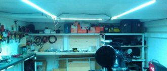
Important: The increase in illumination standards should not exceed a twofold minimum. Also, to protect your vision, you should take into account the reflectivity of the working surface. Lighting in the garage - photo:
Lighting in the garage - photo:
Garage shield device
When installing an electrical panel with your own hands, you need to clearly understand its structure. The incoming electrical cable must be connected to the input circuit breaker, which acts as a switch. It is advisable to use a two-pole circuit breaker as an input circuit breaker. In this way, two cable conductors are disconnected at once. This is done for safety purposes when carrying out repair and installation work inside the panel or in the garage. The fact is that in garage cooperatives, there is often no proper control over the state of electrical equipment and it is possible that on the incoming line the neutral and phase conductors will be swapped.
If the incoming zero is connected bypassing the machine, a situation may arise when, when the machine is turned off, a high potential will be present at the panel components. This is true if single-phase voltage is supplied to the garage. When supplying three-phase voltage, it is optimal to use a four-pole circuit breaker.
After the introductory machine, an electricity meter is connected. Usually this is a household meter, for example, Mercury 201. The phase and neutral conductors coming out of the meter are connected to an RCD (residual current device). The presence of an RCD is necessary to protect people from electric shock. When a person touches a bare live conductor, a leakage current begins to flow through his body. To prevent the leakage current from reaching a life-threatening value, the RCD turns off the voltage supply.
Correct operation of the RCD is impossible without the presence of grounding in the panel. Grounding must be installed in the garage, regardless of the presence of a grounding conductor in the input cable.
From the output terminals of the RCD, the phase is supplied to group circuit breakers, from which voltage is supplied to each electricity consumer separately. The neutral conductor is connected to a metal bus. All neutral conductors from cables going to consumers are connected to the same bus. This bus connects all the grounding conductors present.
All elements of the shield circuit are mounted on a metal plate called a DIN rail. The design of the DIN rail is such that it allows you to quickly attach all elements to it or, conversely, dismantle them. For the zero and ground buses, there are also options for mounting on a DIN rail.
A possible option for placing all components inside the shield.
After installing the components inside the shield, all parts are covered with a protective screen from the shield kit to prevent accidental contact with live parts. The screen must have windows through which switches are made and readings from the electricity meter are taken.
Installation and assembly
Do-it-yourself installation of the electrical panel is carried out in such a way that the electrical connections do not pose a danger to the use and maintenance of distribution and switching devices. The cross-section of the wires supplying and discharging energy must be sufficient to transmit the required power, and the wires themselves must be “dressed” in reliable insulation.
When laying out lines and installing elements according to the electrical panel diagram, the following must be observed:
- requirements for cable cutting and compliance with their colors;
- standards for the location of electrical panels and power lines;
- installation diagrams of switching equipment.
The electrical panel diagram includes the following elements:
- Counter.
- Input two-pole circuit breaker.
- Residual current device.
- Single-pole circuit breakers.
- Connection block for the “0” conductor.
- Ground connection block.
- RCD of individual groups.
Conclusions from the RCD are distributed as follows:
- black (or red) connects to the first single-pole circuit breaker;
- The blue one is screwed to a metal block.
Installation of the electrical panel is done with your own hands at a height of average human height - 1.5-1.8 m. Assemble the box and attach its frame to the wall.
Install a DIN rail bracket on which the breakers and RCDs will be hung. Installation of the slats: it should be 6 cm higher than the bottom border of the box.
If the meter is not installed, hang it on the DIN rail on the right side of the box. The distance from the device to the upper border of the box must exceed 5 cm.
Do-it-yourself electrical panel means installing wires:
- The phase wire makes the connection between the third connection point of the meter and the first (upper left) terminal of the RCD. The blue wire connects the fourth socket of the meter and the third (upper right) contact of the RCD.
- The phase conductor is used to connect, respectively, the second (lower left) contact of the RCD with the upper contact of the single-pole circuit breaker. The blue “zero” wire connects the fourth (lower right) terminal of the RCD to the contact “0” bracket
- Lay jumpers between the upper contacts of the breakers.
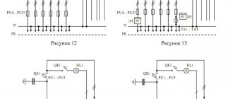
In an electrical panel for a garage, where the installation of protective disconnecting elements for each group is not provided, the phase outlet ends are connected to the lower connectors of each machine, and the “zero” ends are connected to the corresponding block.
If RCDs are provided for separate groups, they need to be assembled and connected.
- The lower terminal of each machine is connected to the upper right contact of the corresponding protective device.
- The “zero” block is connected to the upper left contact of each RCD.
- From the lower terminals of the RCD, the corresponding wires are routed - the phase wire and the “neutral” wire to the distribution boxes of each group of electrical appliances.
In order for the network to function for a long time and without failure, it is worth listening to the advice of experienced electricians on how to properly assemble and connect wires with screw terminals.
And energy consumption will be cheaper: there will be no need to pay for heat losses at the joints.
Supplying electricity to the garage
Every garage cooperative has a main electrical panel. From it cables are routed through the boxes. The ideal option would be to connect the cables from each box directly to the main panel. However, due to the large number of garage boxes and their remoteness, such a connection is not feasible due to high costs. Therefore, other options are used.
The most common method is to route cables from the switchboard to a group of boxes. A group panel is installed on each group, equipped with a switch with fuse links or an automatic circuit breaker designed for high operating current.
A cable is laid from the local panel to the electrical panel in the garage. The structure of the local panel is similar to a garage panel, but it does not have an RCD and an electric meter. To lay the cable, it is placed in a corrugated pipe or metal hose and securely attached to the wall at the maximum possible height. The pipe protects the cable from accidental mechanical damage. For the same purpose, when inserting a cable through a garage wall, protective sleeves are used.
Electrical connection to the cable in the group panel is made only after the final installation of the panel in the garage. All work must be carried out when tension is relieved at the work site.
There is another option for connecting the cable from the garage to the main line. This method is used when, instead of group switchboards, the distribution of electrical cables throughout the territory of the garage cooperative is carried out along lighting poles. In this case, the cable from the garage panel is connected to the main lines on the pole. The connection is made using special clamps or punctures.
The second option is less preferable, because for the safety of work during connection it is necessary to de-energize a large number of boxes. The work itself is carried out at height, which creates additional danger.
Connection diagram for devices inside the electrical panel box
The order of connecting devices inside the electrical panel is well illustrated by the diagram below:
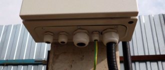
- An input cable with three cores from the line on the pole is led through a prepared channel into the electrical panel. Metal-plastic or steel pipes can be used as hoses or channels through which the wire is passed. It is safer to enter the box through the back wall of the electrical panel, rather than punching a hole in the side wall of the garage;
- Inside the electrical panel, an electric meter, a short-circuit circuit breaker and an RCD protection unit are sequentially mounted on mounting strips. Next, packages are installed for sockets and devices for lighting the garage, a transformer for powering lamps and basement ventilation;
- Using switching blocks, the devices are connected in series in a circuit and connected to lighting wiring and power wires going to the welding station and socket block with a maximum current consumption of up to 25A. The remaining sockets are connected to packets with a cut-off current of 16A.
Advice! Mark the stripped wire sections using colored electrical tape. This will simplify the connection to the blocks and avoid ground-phase confusion.
Often, in order to simplify the work with connecting and sealing the meter in the garage, a regular shut-off switch is installed before entering the electrical panel or a difautomatic device is moved. Usually the electricians of the garage cooperative insist on this, it is easier and more reliable to protect external lighting lamps from short circuits, and it is easier to work with the meter.
The feasibility of such a solution is not always clear, so many motorists can insure themselves and install two machines in the garage, before and after the meter, which is also not always justified.
Sockets and lighting fixtures in the garage are connected by separate packages; they are divided into two groups - power with a threshold of 25A and low-power - for operation on ordinary sockets with a load of no more than 1.5-2 kW. For lighting, weak 5 amperes are sufficient, but it is advisable to install your own switch on the electrical panel for each lighting point in the garage, for example, for a spotlight, carrying and four wall lamps.
A mandatory attribute of an electrical panel mounted in a garage is a complete grounding circuit for the garage wiring. This is extremely important. You shouldn’t really rely on the neutral of the voltage line and trust that it is grounded, as electricians and their assistants say. In addition, if there is a short circuit somewhere on the neutral line, a good potential of up to 120V can appear, which can burn out particularly delicate devices operating in the garage, for example, a battery charging unit. A thick “ground” wire, or better yet a copper bus from a steel circuit buried a meter deep, is connected according to the diagram presented; the electric meter is not shown.
Connection diagram inside the shield
A typical version of the garage panel diagram is presented.
The ratings of the circuit breakers are selected so that in case of a short circuit in the line or the permissible load on the cable is exceeded, the load is disconnected before the conductors heat up to the melting temperature of the insulation. The RCD parameters indicate a leakage current of 30 mA, this corresponds to a safe value to prevent electric shock.
Automatic machines rated 16 A are used on lighting lines or sockets for connecting hand-held power tools. A line with a 32 A automatic machine is designed to use a more powerful load, for example, a welding machine or a heat gun.
You will notice that connecting and installing a garage electrical panel yourself does not pose any particular difficulties if you follow safety precautions and adhere to the connection diagram.
What should be in the shield
Read about how to connect electricity from a pole to a house here.
In some apartment buildings, meters are located in boxes on the staircases. In this case, the cabinet is needed only for RCDs and automatic machines. In other houses it is located in the apartment. When upgrading the electrical network, you will have to buy a cabinet so that the meter can fit in there, too, or buy a separate box for the meter with an input machine.
A simple electrical circuit diagram for a small house or apartment
One example of a panel layout for a small circuit - for 6 machines
The stabilizer is installed on one or several groups and is turned on after the RCD and before the group circuit breakers. Since this is a rather large device, it won’t be possible to install it in a panel, but you can install it next to it.
When assembling an electrical panel yourself, you will need to purchase the cabinet itself, as well as rails (called DIN rails or DIN rails) on which circuit breakers, RCDs and switches are attached. When installing the slats, check with a level that they are horizontal: there will be no problems with fastening the machines.
All machines must be connected to each other. This can be done using conductors - connecting their inputs in series, or using a ready-made connecting comb. A comb is more reliable, although it costs more, but if you take into account the time that you will spend connecting all the machines, it is unlikely that a few tens of rubles are of such fundamental importance.
Connecting comb for circuit breakers in an electrical panel: will speed up the self-assembly process
Scheme for several groups
It is very advisable to install protective devices on each of the inputs that go to powerful household appliances (more than 2.5 kW, and even a hair dryer can have such power). Together with a stabilizer, they will create normal conditions for the operation of electronics.
What is an electrical panel in a garage and what needs to be included in it?
An electrical panel for a garage is a panel on which devices are mounted to ensure the reception and distribution of current in the network. Having a shield in the garage, you can turn off the power during a long absence, minimizing the chance of a short circuit and spontaneous combustion.
Device functionality includes:
- provision of the entire electrical network;
- calculating the amount of energy consumed;
- ability to control energy supply;
- protection against overloads and power supply system failures.
To ensure the normal functioning of the system, it is necessary to determine in advance the amount of electricity consumed in the garage.
Why install an electrical panel in the garage
Electrical panel for the garage
When installing and registering the device, the garage becomes a room that needs to be fully equipped in order to optimize its functionality. When choosing equipment, the layout and area of the room must be thought out in advance. This is due to the fact that these factors determine the volume of electricity consumed. For maximum comfort, the room is divided into several zones:
- The main part intended for storing the car.
- An additional area designed for storing tools, as well as placing a working area and a repair pit.
Many car owners carry out tire fitting and other repairs themselves, therefore, adequate lighting in the room is required. To carry out a large number of works, the installation of a high-quality shield is required.
The right choice of equipment and tools
When choosing an electrical panel for your garage, you should pay attention to several factors:
- Device location. If it will be outdoors, you should choose moisture-resistant models.
- Block material – plastic or metal. It is better to choose an iron shield located outdoors, as it is more resistant to damage.
- Door design: transparent or metal. Depends on the conditions of the electrical panel.
- Installation method: the structure will be built-in or wall-mounted. Depending on the condition of the garage wall and the weight of the panel.
- How many modules are needed? It is recommended to install them in reserve so that you can always connect additional elements. For example, in the case of a three-phase RCD, 4 modules will be needed.
- Is it necessary to equip the garage panel with a charger?
The first thing you need to decide is:
- electrical cable entry point into the garage
- shield location
- socket locations
- lamp locations
- presence of grounding
- the presence of powerful electrical consumers such as a compressor.
We draw a plan of the garage and mark the installation points, and also draw a cable routing diagram. I will do this using my 6x4 garage as an example:
wiring in the garage
If you plan to connect powerful electrical consumers, then you should provide a separate line for them, connected to a separate machine.
Design of a working diagram of an electrical panel
Installation of an electrical panel in a garage is based on studying the layout of the room.
You get it in two ways:
- They draw it themselves in programs (AutoCAD, ArchiCAD, Photoshop, Exel). Self-created diagrams, in the absence of proper skills in working with programs, usually do not correspond to reality or are not accurate.
- Use the electrical network diagram, which is located in the premises’ energy supply project, if one is available.
Each of the schemes is individual, but regardless of the level of training, it should contain the following elements:
- designations of all modular automation;
- all cross-sections and loads of cables.
Installation
Installing an electrical panel requires certain skills and therefore you need to familiarize yourself in advance with how to install it. This will help you complete the installation work correctly. Equipment installation is carried out in three successive stages:
- Housing fastening. The choice of installation method depends on the type of wiring in the garage. If it is open, you will have to use the hanging method, in which the shield is attached to the wall with screws at a height of 80-90 centimeters. If the wiring is hidden, a special cavity is made in the wall into which the shield is placed.
- Connecting the meter. After installing the panel housing, begin connecting the meter. Most network companies insist that the device be connected directly to the network. This will prevent electricity theft. You can connect the meter yourself or use the services of specialists.
- Installation of machines. They are connected to the panel so that you can independently disconnect individual electrical lines.
Features of electrical panel assembly
To avoid accidents or shortcomings during the installation of an electrical panel, you need to know a few nuances.
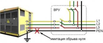
The first feature is the neutral conductor. Some craftsmen connect the grounding to the neutral conductor, but in this design, when the wire burns, a charge of electricity passes through the body of the shield, which creates a situation dangerous to human life. If connected correctly, the phase wire is connected from below to the grounding block.
The second feature is three-phase power. The assembly of an electrical equipment panel with three-phase power supply occurs with uniform voltage distribution. This will provide protection against phase imbalance, since the consumer can be a powerful household device, for example, a welding machine.
All 3 phases are connected separately, depending on the amount of electricity consumed.
Equipment for shield assembly
Before you start, you should prepare and purchase all the necessary elements.
To assemble the electrical panel you will need the following set of tools and equipment:
- a certified electric meter, which must have a mark indicating that it has been tested by the Energosbyt company;
- wires;
- automation;
- stripper - a tool for stripping insulation; if not available, it can be replaced with a knife;
- insulated pin sleeve lugs (NSVI), used for fixing wires;
- residual current device (RCD);
- press pliers for crimping insulated tips;
- terminals - electrical installation device for reliable connection of wires;
- a comb for conducting electricity through all devices of the panel;
- metal profile for fastening modular equipment;
- other optional tools.
Assembly procedure and installation
Garage shields are a unique design consisting of a protective block and the system itself, so they are quite convenient to assemble without special space.
This happens in several stages:
- Labeling and location of automation. In most models of electrical panels, devices are located on DIN rails - metal profiles. To prevent them from driving, you can use limiters. It is better to label the conductors, this will help to quickly determine their purpose.
- Preparing connections. The wires should be stripped of insulation and threaded into NVSI lugs, which will then need to be compressed. It is important to do this correctly: the length of the tip must be equal to the length of the wire stripped of insulation. The comb for connecting the machine and the RCD must be of the same brand as the devices, since the pitch of the pins may differ. The terminals of the devices must be securely fastened, otherwise they will overheat and the insulation will be damaged, leading to a short circuit.
- Fastening parts. At this stage, the automation is connected to the RCD, switches, UZM and other components. It is necessary to monitor the quality of the bond, because this is the only way to avoid bad contact.
- Examination. The panel in the garage must be tested by applying voltage to the input circuit breaker or switch. At the end of the assembly, you should mark all the switches and what is connected to what.
Making an electrical panel in a garage with your own hands is not easy, but following all the recommendations, even a beginner can do it. It is important to choose the right equipment and correctly connect the devices and wires to each other.
Required Tools
At the preparatory stage, you will need to decide on a set of tools necessary for installing electrical wiring in the garage. Their list includes the following items:
- flat and Phillips screwdrivers (preferably several sizes);
- pliers and round nose pliers (the latter are needed in order to accurately connect the wires to the machines);
- a hammer drill and a grinder for making grooves and niches for sockets.
You will also need a special tool to install the cable-retaining mounting brackets, as well as a voltage meter or gauge. The latter is necessary to check the absence of voltage in the line, that is, to ensure the safety of the work being carried out. Consumables required include insulating tape and polyvinyl chloride-based tubes.
Possible garage lighting options
Electrification of a garage, which belongs to the class of utility rooms, is a whole complex of measures. In order to better imagine the implementation of each stage of this work, it is necessary to become familiar with the types of lamps that can be used for lighting. Each of them has its own advantages and disadvantages.
Types of lighting fixtures for the garage
- Incandescent lamps are a traditional and very affordable type of lighting. They have a low price, but their service life is short. Yellow spectrum of emitted light and a large amount of heat generated. Efficiency - no more than 45%, consumes a lot of electricity.
Incandescent lamps are an outdated type of lighting technology and are rarely used today
- Halogen lamps are well-proven lamps that emit an even and bright light. The principle of operation is the same as that of the “Ilyich light bulb” - a tungsten filament is heated in a flask filled with bromine vapor. Halogen lamps have a long service life - up to 5,000 hours. The disadvantage is sensitivity to voltage changes in the network and a large amount of energy consumed. Operation without a protective shade and the appearance of greasy stains on the surface of the glass bulb significantly reduce its service life.
Halogen lamps should not be touched with hands, otherwise they will quickly burn out.
- Fluorescent lamps. A fairly common type of lighting for garages. It is convenient because it gives an even, “cold” light. Electricity consumption is significantly lower than that of incandescent lamps. Long service life. The principle of operation is that the phosphor covering the inner surface of the bulb glows under the influence of ultraviolet rays. Disadvantages include the increased content of mercury vapor, which can cause damage to health. In addition, when the voltage drops, such a lamp may operate unevenly, causing a flickering effect.
Fluorescent lamps have a long service life and consume less electricity than incandescent lamps
- Energy-saving lamps. One of the most profitable lighting options. It features low power consumption, good light output and long service life. There is a large selection of glow shapes and colors on sale (matte, yellow, white, etc.). Disadvantages - the price is above average and mercury vapor fills the inside of the lamp.
Energy-saving lamps (ESLs) consume a minimum of electricity, but are expensive and contain mercury vapor
- LED lights. High performance characteristics - low energy consumption, long service life (up to 100 thousand hours), even, bright light. A huge advantage is the safety of such lamps. The downside is the high price.
Electrical panel diagram
And finally, the electrical panel. Let's consider its diagram.
Input electrical panel diagram
The voltage from the street input is supplied to the electricity meter through input circuit breaker 1 and distributed from it over four lines:
- through circuit breaker 2 to the main lighting;
- through circuit breaker 3 and RCD 4 to sockets;
- through circuit breaker 5 and RCD 6 to a 220/12 V transformer;
- through circuit breaker 7 and RCD 8 to the compressor.
Important! The rated currents of the machines are taken conditionally. They must be selected individually depending on the load on each line
The article “Design and main characteristics of circuit breakers” will help you in choosing circuit breakers.
What types of counters are there?
When it is necessary to replace or install an electric meter in a garage, not every car enthusiast will be able to figure it out and choose the right type of device. To avoid purchasing the wrong option, you should know in general terms the difference between the types of electric meter.
There are many of them, but let’s look at the two main ones by type of design – electric and induction.
Electronic counter
The modern type of electric meter has many advantages, including:
The main disadvantages are high cost and shorter service life compared to induction.
Induction
The induction device is considered a classic option; it appeared much earlier and can often be found in old buildings.
The device has a simple design and operates on the principle of a magnetic field generated by two coils - voltage and current. As a result, the magnetic field exerts an effect on the disk, and it carries out rotational movements. Induction meters are durable. Among the advantages it is also worth noting reliability and low price. However, the main drawback is significant - the low accuracy class, which can cause overpayment for bills.
Also, a mechanical meter has weak protection against the theft of electricity, and when taking into account several types of electricity, you will have to use several devices.
Three-phase meters
In addition to differences in structure and operating principle, electric meters are also divided according to measured values into single-phase and three-phase. The first ones are connected to a 220V network and are used both in apartments and garages.
Connection has a number of advantages:
Connection method and accounting type
Meters are selected not only according to the principle of operation, but also according to the connection method and type of electricity metering. Three-phase devices are connected directly or indirectly. Direct connection is a connection to the network without instrument transformers.
In this case, the installation scheme is the simplest - the meter is installed directly into the break in the supply wires. This method is used with a small number of low power consumers. If there are powerful consumers, then an indirect connection using intermediate transformers is used.
You should also pay attention to the type of metering, since this item will help save money if you use three-phase equipment. During operation of the device, reactive and active energy is consumed
Operation of protection devices
The protection system mounted on the electrical panel consists of two mandatory devices. The first is a device or circuit breaker when a short circuit occurs. The second is an RCD device; both devices are very similar in appearance, and they are often confused and do not understand why there are two identical machines.
In fact, the RCD circuit is fundamentally different from the main automatic cut-off device, and is designed to disconnect the wiring only in cases where the leakage current between two cable cores reaches 5 thousandths of an ampere. There are many cases when, standing on wet ground, a person touches the body of an electrical device and receives a blow due to a violation of the device’s insulation. Most often this happens due to microcracks in the polyvinyl chloride insulation of the cable, or when the wiring becomes soiled from condensation and rainwater flowing through the garage roof. One hundred thousandths of an ampere is considered fatal; a working RCD should trip at five thousandths, but is not capable of disconnecting the network if a short circuit occurs.
For these purposes, differential devices are used to automatically turn off the power when the current sharply increases to a certain threshold. If you have powerful welding equipment in your garage, then install the device at 25A. This is no longer possible, this could lead to a fire in the wiring and electrical panel in the garage. For more powerful consumers, a three-phase network will be required.
What is an electrical panel?
An electrical distribution panel is a small panel that is used to install equipment responsible for supplying a room with electricity. Many people consider such devices to be very convenient, since they can install all the necessary switches and electrical mechanisms. This makes it easier to disconnect the garage from electricity, as all you need to do is use a few levers.
When making panels, they use lightweight materials, which simplify their installation in the garage. Most models are equipped with special security doors that are locked with a key. They help prevent accidental contact with equipment inside. Some modern models have doors that close hermetically. This will protect the switchboard from precipitation if it is installed outside the garage.